1
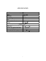
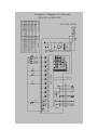
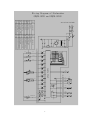
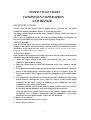
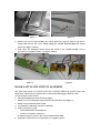
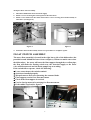
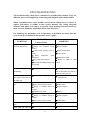
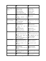
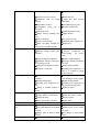
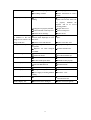
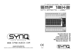
EQUATOR
SERVICE MANUAL
AND
SPARE PARTS CATALOG
First Edition - March 2005
18" DISHWASHERS
MODEL: WB 818
SB 818
www.EquatorOnline.com
Advanced Appliances
CONTENTS
SPECIFICATIONS……………………………………3
SCHEMATIC DIAGRAM……………………………… 4
WIREING DIAGRAM……………………………………5
TIMER CYCLE CHART………………………………… 6
COMPONENT OPERATION AND REPAIR……………… 7
Safety Precautions…………………………………………… 7
Timer……………………………………………………………………7
Door Latch and Switch Assembly…………………………………… 8
Float Switch Assembly…………………………………………… 8
PRODUCT EXPLODED VIEWS…………………………………10
TROUBLESHOOTING……………………………………………
2
14
SPECIFICATION
MODEL
Rating
Motor (HP)
Motor (Amps)
Heater Wattage
Wash
Total Amps (Load Rated)
Thermostat Contacts
Close at
ELECTRICAL
120V 60Hz
1/5
1000W
9.2A
127°F ±5°F
58℃±3℃
WATER SUPPLY
Suggested Min. Incoming Water 120°F to 150°F
49℃ to 66℃
Temperature
Pressure (PSI) Minimum/Maximum
15/120 PSI
Connection (NPT)
3/8”
3.5±5%
Consumption (Toil Gallons)
1.08GPM±10%
Water Valve Flow Rate (GPM)
3
Schenmatic Diamgram of Dishwasher
(WQP8-9223 and WQP8-9324)
code
component
L
G
N
IG
code
thermic-hypersensitive switch
SMP20 1
C1
T1
D12
D15
D13
C2
ACN
11
D-LED
D1
D2
D3
D4
D5
D6
D7
D8
10
TR2
S
PS
K1
K2
K3
K4
TR3
19
9
TR4
EV1
IS
8
TR6
P1
SMP16
D/Ed
17
TR7
contoller
18
TR5
EV2
2
1
1
9
3
TR8
7
3
1
3
11
2
5
6
TR10
BUZ
IAQS
TR9
16
13
RE
VCC
7
RY1
D9
15
RY2
5
D10
16
ISS
15 8
ISB
R1
D11
ACN
ACL
13
4
D14
20
TR1
MIC1
S
ML
ITR(78)
C3
C4
component
7805
D/Ed dispenser
EV2 softener valve
C
power switch
IG
quicksilver switch
ISB
thermic-hypersensitive switch
ITR
rinse aid warning light
D9
washing pump
ML
water level switch
P
thermic-hypersensitive resistance
RE
VCC
Cn
EV1
IAQS
IS
ISS
LS
D10
PS
R1
S
capacitor
inlet valve
flowt switch
door switch
salt switch
power switch
salt warning light
drain pump
heating element
AC110/120V 50/60Hz
Wiring Diagram of Dishwasher
(WQP8-9223 and WQP8-9324)
component
L
G
N
C1
D12
D15
D13
ACN
11
D-LED
TR5
18
TR10
K1
K2
K3
K4
TR4
6
white
9
TR6
TR1
20
SMP16
TR3
17
1
3
S
9
2
P1
1
20
TR2
red
contoller
IS
S
ML
PS
3
1
2
11
3
IAQS
TR9
16
white
5
BUZ
13
pink
TR8
RE
VCC
black
7
RY2
ISB
5
gray
D9
16
15
D10
RY1
15 8
black
IG
1
T1
D14
D1
D2
D3
D4
D5
D6
D7
D8
TR7
17
C
R1
D11
ACN
ACL
13
5
C2
C3
SMP20
EV1
green
white
ISS
gray
ITR(78) pink
red
green
C4
component
EV2
white
SMP20
code
7805
D/Ed dispenser
D/Ed
EV2 softener valve
power switch
IG
quicksilver switch
ISB
thermic-hypersensitive switch
ITR
rinse aid warning light
D9
washing pump
ML
water level switch
P0
thermic-hypersensitive resistance
RE
yellow
VCC
capacitor
inlet valve
flowt switch
door switch
salt switch
power switch
salt warning light
drain pump
heating element
thermic-hypersensitive switch
white
green
code
Cn
EV1
IAQS
IS
ISS
LS
D10
PS
R1
S
red
gray
gray
AC110/130V 50/60Hz
gray
TIMER CYCLE CHART
COMPONENT OPERATION
AND REPAIR
SAFETY PRECATIONS
Always turn off the electric power supply before servicing any electrical
component, making ohmmeter checks, or replacing any parts.
All voltage checks should be made with a voltmeter having a full scale range of
130 volts or higher.
After service is completed, be sure all safety-grounding circuits are complete, all
electrical connections are secure, and all access panels are in place.
CIRCUIT BOARD
With the circuit board, user selects the various cleaning cycles of the dishwasher
with press the button. The circuit board controls all the electrical functions of the
dishwasher in all stages of each cycle. All functions can be traced on the chart.
Diagram provided in this service manual.
To Test Circuit Board
If the circuit board is suspected of faulty operation, reference chart and electrical
schematic diagram and proceed as follows:
1. Index the circuit board to all of the increment of the cycle, each of the
indicators light should is bright.
2. Index the circuit board to one of the increment of the cycle, which is a drain
period.
3. If the pump motor fails to operate during the first cycle increment, check for
power at the pump motor connector block, if there is no power check the
door latch switch, if there is power, check the pump motor as described in this
section.
4. If a component controlled by the circuit board fails to function as the circuit
board advances through the cycle, check for voltage at the circuit board
terminals. If the check voltage is supplied to the component, check the
component as described in this section.
Continuity through circuit board contacts, other controls, and wires can also
be checked with an ohmmeter with electrical power disconnected.
If the circuit boards contacts fail to close in the sequence shown on the chart
are burned (have resistance measurable with an ohmmeter), or if circuit
board does not run automatically, replace the circuit board.
To Replace Circuit Board
1. Disconnect dishwasher from electrical supply.
2. Remove the power button.
6
POWER BUTTON
Figure 1
Figure 2
3. Remove the screws which locking the control panel (See figure1). Remove the power
button and unscrew the screws which locking the circuit board behind the control
panel. (See Figure 2 and 3.)
4. Take down the damaged circuit board and install a new circuit board, reverse
procedures to complete repairs. (See figure 3and 4.)
Figure 3
Figure 4
DOOR LATCH AND SWITCH ASSEMBLY
The latch and switch are located in the door assembly behind the control panel. The
dishwasher will not operate until the door is closed; the latch engages the door catch.
To Test Or Replace Door Switch.
1. Disconnect dishwasher from electrical supply.
2. Remove screws securing the control panel to the inner door (See Figure 1).
3. Remove wire leads from latch switch.
4. Use ohmmeter and check switch for continuity.
5. If the switch tests is good.
Check dishwasher electrical power.
Check to see if timer is defective.
If switch is defective remove door switch from latch assembly.
6. Install new switch and reverse procedures to complete repairs.
7
To Replace Door Latch Assembly
1. Disconnect dishwasher from electrical supply.
2. Remove screws securing the control panel to the inner door.
3. Remove wire leads from door latch and remove screws securing door latch assembly to
inner door. (See Figure 5.)
SCREW
FLOAT SWITCH
WIRE
LEAD
SWITCH
DOOR
WIRE LEAD
LATCH
Figure 5
Figure 6
4. Install new door latch assembly and reverse procedures to complete repairs.
FLOAT SWITCH ASSEMBLY
The water float assembly is located in the right lower side of the dishwasher (the
portable located behind the lower front crosspiece). When too much water enter
the dishwasher,the water will enter the float support through the overflow pipe,
the float will make the floating switch acts, the electrical supply to the water
valve will disconnected and the drain pump keep on working.
If the switch fails to operate, check the following:
● Loose connection at the switch terminal.
● Switch not installed properly.
● Warped stem on float, not contacting the actuator blade.
● Float support restricts free float movement.
● Check if the float support is cracked.
● Food or foreign material restricting free float movement.
● If the rubber cap lost(See figure7).
RUBBER CAP
THERMOSTAT
SENSOR
8
Figure 7
Figure 8
To Remove Or Replace Float Switch
1. Disconnect dishwasher from electrical supply.
2. Remove electrical leads to float switch.
3. Take down the switch from float support.
4. Install new float switch and reverse procedures to complete repairs (See
figure 6).
9
TROUBLESHOOTING
The troubleshooting cheek list is common for all dishwasher models. They use
different parts to accomplish the same thing and diagnosis will remain similar.
When a problem arises, and a possible cause is listed, follow the test, remove or
replace procedures as outline in this service manual. The wiring diagram,
shematic and timer cycle chat is a necessity when making electrical checks. In
most cases an ohmmeter will handle all the tests necessary.
For checking any particular cycle of operation, it absolutely necessary that the
cycle be set up as outlined in the product owner’s guide.
CHECK THE
FOLLOWING
SYMPTOM
Dishwasher
will
not
operation when turn on
REMENDY
●fuse (blow nor tripped)
◇Replace fuse or reset breaker.
● Supply line receptacle, wiring
◇Repair or replace.
harness.
● Circuit board (contacts open or
◇Replace circuit board.
burnt).
◇Replace motor.
●
Motor
(inoperative,
check
resistances).
◇Replace door switch.
●Door switch (open contacts)
◇ Replace or adjust to make
●Door latch not making contact with
contact.
door switch.
Dishwasher
stop
washing
● Overflow occur.
◇ Check the reason of overflow
but draining
pull out the rubber cap wait for a
minute let water pour out.
Water can’t pour out from
●Hole in the float supply is jammed.
float support when pull out
◇Suck
with dust cleaner or other
let water pour out.
the rubber cap.
Dishwasher runs but not
●heater element (open).
◇Replace heater element.
heat
●Timer contacts (open or burnt).
◇Replace timer.
● Wiring or terminal (burnt or
◇Repair or replace.
broken).
Dishwasher will not stop.
● Thermostat is closed.
◇Replace.
●Timer motor (inoperative).
◇Replace timer.
● Wiring or terminal (burnt or
◇Repair or replace.
broken).
Dishwasher runs with door
●Timer (open or burnt contact).
◇Replace timer.
●Defective door safety switch.
◇Replace door safety switch.
●Start winding(open).
◇Replace motor.
open
Motor hums but will not
10
● Motor (bad bearings or locked
start or run.
◇Replace motor.
rotor).
●Start relay not dropping out.
◇Replace start relay.
terminal thermal overload
●Improper voltage.
◇Check voltage.
protector.
●Seal faces binding.
◇Repair or replace.
●Motor shaft binding.
◇Repair or replace.
●Motor windings shorted.
◇Repair motor.
●Glass or foreign items in pump.
◇Clean and clear area.
● Circuit board (contacts open or
◇Replace circuit board.
burnt)
◇Replace timer.
Motor
trips
out
on
in
Repeated dishwasher cycles
●
Motor
(inoperative,
check
resistances).
● Damaged circuit board.
◇Replace circuit board.
●Check circuit for power ,check if
◇ Reconnected wire and circuit
the wire misconnected.
board .
●Have wire cut off
◇Repair.
Dishwasher will not fill with
●Water supply turns off.
◇Turn water supply on.
water.
●Defective inlet valve.
◇Replace inlet valve.
Dishwasher
does
not
advance automatically.
●
Check
valve
screen
for
◇Disassemble and clean screen.
obstructions.
Incomplete water fill.
●Defective float switch.
◇Replace switch.
●Damaged circuit board.
◇Replace circuit board .
●Wiring (broken or burnt).
◇Repair or replace.
●Low water pressure.
◇ Minimum water pressure of
15P.S.I
●Clogged water inlet valve screen.
◇Clean water inlet valve screen.
● Heavy
◇ Use dishwasher when water
water
supply
usage
elsewhere in home.
usage is at a minimum.
●Kinked or restricted fill hose, water
◇Correct as needed.
inlet valve to fill tunnel.
Too much water fill.
●Water inlet fill valve defective.
◇Replace water inlet fill valve.
● Damaged circuit board
◇Replace circuit board.
(open or
burnt).
● Float arm binding or out of
◇Repair, adjust or replace.
adjustment.
Dishwasher will not pump
●Drain pump is restricted.
◇Clear restrictions.
out.
●Damaged impeller.
◇Replace drain pump.
●Wiring or terminal (contacts open
◇Replace circuit board.
or burnt).
Water siphons out.
Water leaks.
●Drain hose loop to low.
◇Move to proper height.
● Drain line connected to a floor
◇Install vent air gap at counter
drain not vented.
top.
●Spray arm not rotating or split.
◇ Check for proper rotation or
replace spray arm.
11
●
◇ Check and correct for proper
Overcharge of water.
fill.
●Tub seal (torn, worn or loose).
◇Replace tub seal.
● Dishwasher
◇ Adjust door latch assembly
door
not
sealing
properly.
and/or strike.
●Dishwasher is not level.
◇Level dishwasher properly.
● Overburden
(wrong
type
of
◇Instructs customer/user.
detergent).
●Hose clamps loose.
◇Tighten all clamps securely.
● Heater element mounting nuts
◇Tighten the nut.
loose.
●Water seal leaking.
◇Use a new water seal.
●O-ring is not in position.
◇Adjust the ring or replace a new.
● Motor and pump assembly not
◇Replace seal.
seated proper in tub liner bottom.
Poor wash ability.
●Spray arm not rotating.
◇Check for proper rotation.
●Improper loading of dishes, pans
◇ Instructs
and other.
proper loading
customer/user
per
on
owner’s
guide.
●Detergent dispenser inoperative.
◇Repair or replace dispenser.
● Insufficient amount of detergent.
◇On proper amount of fresh deter
Or the detergent is old.
gent to use.
●Damaged or the impeller is broken.
◇Replace pump assembly.
●Detergent
◇Incoming water temperature
not dissolve.
140 ° F
of
is required to proper
dissolve detergent.
Poor drying of dishes
● Improper loading of dishes, pots
◇ Instruct
and other.
proper loading per owner’ s guide.
●Heating element (open).
◇Replace heating element.
● Incoming water temperature too
◇Incoming water temperature of
low.
140°F for best drying results.
● Wiring or terminal (broken or
◇Replace or repair.
customer/user
on
burnt).
●Cup binding.
◇Repair or replace.
●Roll pin retainer or shaft broken.
◇Replace pin, retainer or shaft.
●Defective bi-metal.
◇Repair or replace.
●Timer contact (open or broken).
◇Replace timer.
Door will not lath.
●Door latch damaged.
◇Replace door latch.
Rinse agent liquid will not
●Electromagnetic valve defective.
◇Replace valve.
eject.
●Rinse agent dispenser not mounted
◇Mount securely to rear of inner
correctly.
door panel.
● Plunger stuck or held in closed
◇Free plunger or adjust plunger
position.
release.
●Container cracker or broken.
◇Replace container.
Detergent cup will not open.
Rinse agent liquid leaks.
12
●Defective seal on plunger.
◇Replace plunger.
●Over filling container.
◇ Follow instructions in owner’s
manual.
Noisy pump assembly.
●Impellers not properly shimmed or
◇ Use shim gauge furnished in
rubbing.
impeller and seal kit, when seals
are
properly
impellers
will
shimmed
be
in
the
correct
operating position.
●Pump parts not properly installed.
◇Inspect and correct.
●Debris in bottom of tub sump area.
◇Clean out sump area.
●Defective motor bearings.
◇Replace motor.
Dishwasher continues to fill
● Something
or continues to fill even
material) under diaphragm in water
though in case of there is no
inlet valve.
voltage to fill valve.
●Defective water inlet fill valve.
◇Replace water inlet valve.
Detergent left in dispenser.
●Detergent cup held or blocked by
◇On proper loading dishes.
(dirt
or
foreign
◇ Clean water inlet valve or
replace.
large dishes.
● Dispenser wet when detergent
◇Instructs customer/user.
was added.
●Softener broken.
◇Replace softener.
●Softener nut loosen.
◇Screw down softener cap.
●Air inlet nut loose.
◇Screw down air inlet nut.
●Air inlet install up side down.
◇Reinstall air inlet properly.
●Inlet Valve Damaged.
◇Replace Inlet Valve.
●Inlet Valve Disconnected.
◇Reconnected Line.
Window Display “E2”
●Pressure Switch Damaged.
◇Replace Pressure Switch.
Window Display “E3”
●Heating Element (open).
◇Replace.
●Power Supply To heating Element
◇Reconnect
Softener leaking
Leaking form air inlet.
Window Display “E1”
Line.
Cutting.
Window Display “E4”
●Float Switch Act.
◇Take Remove The Rubber Cap
Let Water Pour Out.
Window Display “E5”
●Thermostat Sensor Damaged.
13
◇Replace sensor(See figure8).