1
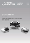
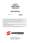
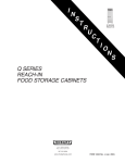
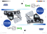
INSTALLATION, OPERATION AND MAINTENANCE MANUAL
EMI AMERICA SERIES
MULTI-ZONE LIMITED RANGE HEAT PUMP
CONDENSING UNITS
S2HA & T2HA HEAT PUMPS
Nominal Circuit Capacities:
9,000 12,000 18,000 & 24,000 Btuh units.
S2HA Multi-Zone
T2HA Multi-Zone
Enviromaster International LLC
5780 Success Dr.
Rome, NY 13440
www.enviromaster.com
An ISO 9001-2000 Certified Company
P/N# 240006458 Rev. 1.1 [04/07]
EMI AMERICA SERIES MULTI-ZONE HEAT PUMP CONDENSING UNITS
INSTALLATION, OPERATION AND MAINTENANCE MANUAL
P/N 240006458, Rev. 1.1 [04/07]
This manual is intended as an aid to qualified service personnel for proper installation, operation,
and maintenance of these EMI America Series multi-zone heat pump condensing units. Read
the instructions thoroughly and carefully before attempting installation or operation. Failure to
follow these instructions may result in improper installation, operation, service, or maintenance,
possibly resulting in fire, electrical shock, property damage, personal injury, or death.
Shipping Damage MUST be Reported to the Carrier IMMEDIATELY!!!
Examine the carton for signs of damage if any is evident open packaging and
check the unit for shipping damage.
SAFETY INSTRUCTIONS
TO THE INSTALLER
Read all instructions before using
the EMI America Series multi-zone
heat pump condenser. Install or
locate this unit only in accordance
with these instructions. Use this
unit only for its intended use as
described in this manual.
(1) Retain this manual and warranty for future
reference.
(2) Before leaving the premises, review this
manual to be sure the unit has been
installed correctly and run the unit for
one complete cycle to make sure it
functions properly.
Check the rating plate on the EMI
America Series multi-zone heat
pump condenser before installation
to make certain the voltage shown
is the same as the electric supply
to the unit.
To obtain technical service or warranty
assistance during or after the installation
of this unit, check our website @ www.
enviromaster.com or call your installing
contractor or distributor. Our technical
service department may be contacted at
1-800-228-9364.
The EMI America Series multi-zone
heat pump condenser must be connected only to a properly grounded
electrical supply. Do not fail to properly ground this unit.
When calling for assistance, please have
the following information ready:
• Model Number___________________
Turn off the electrical supply before
servicing the EMI America Series
multi-zone heat pump condenser.
• Serial Number___________________
Do not use the EMI America Series
multi-zone heat pump condenser if
it has damaged wiring, is not working properly, or has been damaged
or dropped.
• Date of installation________________
!
DANGER
!
Tampering with the EMI America
Series condenser is dangerous
and may result in serious injury or
death. Tampering voids all warranties. Do not attempt to modify or
change this unit in any way.
Multi-zone Heat Pump Condensing Units
[Save These Instructions]
!
3
Recognize this symbol as an
indication of important
!
safety information.
www.enviromaster.com
EMI AMERICA SERIES MULTI-ZONE HEAT PUMP CONDENSING UNITS
SYSTEM OPTIONS
DESCRIPTION
• Sea Coast Style Coated Coils /
Copper-Copper coils
• Wind Baffles - Louvers•
EMI offers the finest multi-zone heat pump
outdoor units in the ductless split market,
the S & T series (S2HA, T2HA, T3HA &
T4HA) Condensing Units. The S & T series
(S2HA, T2HA, T3HA & T4HA) allows the
installation of two or more circuits from a single
outside location when space or aesthetic
requirements limit the use of the number of
cabinets outdoors. Each zone is independent
so no mixing of refrigerant occurs.
When specifying heat pump(s), it is
recommended that the matching indoor
unit(s) be equipped with electric heat. The
S & T series (S2HA, T2HA, T3HA & T4HA)
Condensing Units will operate down to 35°F
outdoor temperature, at which point it will
initiate change over to electric heat and
shut down the condenser. All 9,000, and
12,000 Btuh circuit units are equipped with
the Duratec Performance Package which
include a large capacity suction accumulator
with surge baffles and enhanced oil
management, a factory installed solid core
filter drier and loss of refrigerant charge
protection. All 18,000 and 24,000 Btuh
circuit units include a solid core filter drier
and high pressure limit switch. The 18,000
Btuh circuits also include a large capacity
suction accumulator with surge baffles and
enhanced oil management.
NOTE: The crankcase heater is installed
with 9,000 and 12,000 Btuh heat pumps.
CONTROLS AND COMPONENTS
(FACTORY INSTALLED OR SUPPLIED)
• Compressor and Fan Motor Contactor
• Capacitor
• Loss of Charge Switch (9&12 Only)
• Low Voltage Connections
• Large Capacity Suction Accumulator
(9, 12, & 18 Only)
• High Pressure Control (18 & 24 Only)
• Solid Core Filter Drier
• Crankcase Heater (9&12 Only)
• Common suction pressure access point
• Hard Start Capacitor
Multi-zone Heat Pump Condensing Units
INSTALLER SUPPLIED ITEMS
• Power wiring
• Low Volt wiring - 18 AWG minimum
• Secure mounting pad or foundation
• Refrigerant piping
• Disconnect switch
ITEMS FOR CONSIDERATION
• Locate the unit as close to the indoor section as possible. Maximum length allowed
is 100 equivalent feet.
• Avoid high traffic areas and prevailing
wind locations.
• Surface must be level.
• Mount unit above typical snow levels.
Ensure free flow of air through the unit. Air
must not recirculate from discharge to intake. Air is drawn through the coil with side,
or top discharged through the fan grille. A
minimum 48” clearance is necessary
for the condenser discharge. Intake
(coil side) clearance is 12” minimum.
Consider how power will be run to the unit
from the power source. Refrigerant piping
must be a direct line to the indoor unit.
Heat pump units produce condensate in the
heat pump mode. Water will drain from the
unit at the base. Place the unit so as not to
create a hazard for pedestrians.
SITE PREPARATION
Place the unit on a flat concrete surface or
pad if on the ground. Roof mounting should
use a build up platform. Piping is through
the wall or roof directly to the unit. In areas
of heavy snowfall, condensers should be
set above the level of maximum anticipated
snowfall (12” is usually adequate).
4
www.enviromaster.com
S2HA INSTALLATION INSTRUCTIONS
NOTE: For T2HA installation refer to the T2HA Installation Instruction in this manual.
S2HA UNIT MOUNTING SECTION
Side discharge unit allows for permanent
mounting through the feet. This is highly
recommended due to the vertical design
of the unit.
Accumulator
Compressor
Capacitor
1. Loosen the screws on left and right sides
of the front panel. (Do not remove these
screws.)
Filter Driers
Lag Bolts
5. Insert lag bolts through the holes in
the bottom of the unit and tighten to
secure.
2. Remove the screws on the front of the
panel.
3. To remove front panel:
6. Insert lag bolts through the holes in the
feet on the back of the unit and tighten
to secure.
7. Replace the front panel, do not tighten
the side screws at this time.
4. Slide front panel forward to clear side
screws and remove.
Multi-zone Heat Pump Condensing Units
5
www.enviromaster.com
S2HA ELECTRICAL WIRING INSTALLATION SECTION
!
DANGER
!
The EMI America Series condensing
unit must:
• Be connected to a properly grounded
electrical supply with the proper voltage
as stated on the rating plate.
3. Use only HACR type breakers or time
delay fuses. Select the wire size according to the ampacity rating.
4. To access electrical connections and
wiring diagram:
a) Remove the screws on the side panel
adjacent to the back panel.
b) The screws adjacent to the front
panel should already be loose (don't
remove them).
• Have proper over current protection (i.e.
time- delay fuse/HACR-Breaker) as listed
on the Rating Plate.
Failure to follow these instructions can result in a fire, explosion, or electrical shock
causing property damage, personal injury,
or death.
!
DANGER
!
Do not use the EMI America Series
condensing unit with any electrical supply
voltage other than the one listed on the
rating plate.
Check the rating plate on the unit for the
correct voltage rating. Failure to use the
correct voltage may result in death, serious
bodily injury or property damage. If you have
any questions or doubts, consult the factory
before installing this unit.
c. Slide the side panel out to access the
high/low electrical connections and
wire diagram.
1. All electrical wiring must be run according
to NEC and local codes.
Note: Remove the plastic edge guards
from the holes and replace with a watertight strain relief fitting (High V) and a
split grommet fitting (Low V)
2. Refer to the unit rating plate for voltage,
minimum circuit ampacity and over current protection requirements.
5. Power should be run to a weather proof
disconnect box usually within 3 feet of
the unit.
Rating
Plate
6. From the disconnect box, run the power
through the 7/8" hole on the side of the
unit and into the electrical box and anchor with the strain relief fitting.
7. Run wires to the high Volt pigtail in the control box and attach L1 and L2 connections.
Also run green wire to ground wire.
Multi-zone Heat Pump Condensing Units
6
www.enviromaster.com
S2HA ELECTRICAL WIRING INSTALLATION SECTION
Inside electrical
access panel.
Note: Refer to the
units’ wiring diagram
for all wiring.
Wire Diagram
8. Check wiring diagram for the required number of low voltage wires
to be run between indoor and outdoor sections.
Low Volt
High Volt
Plastic Edge Guards
9. Connect the 24 Volt wiring matching color
to color. Refer to the wiring diagram on the
inside panel of the condenser, and also
refer to the wiring diagram on the indoor
unit. Low Volt interconnect should be at
least 18 awg.
Low Volt Connection
10. To replace side panel slide the slotted
holes of the panel onto the loosened
screws of the front
panel so that the
edge of the front
panel covers
the edge of the
side panel.
Completed
Electrical Connections
11. Tighten all remaining loose screws.
Multi-zone Heat Pump Condensing Units
7
www.enviromaster.com
T2HA INSTALLATION INSTRUCTIONS
NOTE: For S2HA installation refer to the S2HA Installation Instruction in this manual.
After the T2HA unit is positioned on the concrete slab or platform (refer to the Site
Preparation in the front of this manual) the T2HA is ready for installation:
1. Remove the screw on the back panel.
ELECTRICAL WIRING
1. All electrical wiring must be run according
to NEC and local codes.
2. Refer to the unit rating plate for voltage,
minimum circuit ampacity and over current protection requirements.
3. Use only HACR type breakers or time
delay fuses. Select the wire size according to the ampacity rating.
emove panel to expose eletri2. Remove
cal wiring.
Low Volt
Remove the
four screws
on the front
panel
High Volt
3. Location of electrical and tubing connections on back of unit (T4C shown).
4. To access wiring diagram:
a) Remove the four screws on the front
panel of the unit and slide the panel
down until
the upper
edge is free,
then remove
the panel.
Common
Suction
Pressure
Access
Point
b) The wiring
diagram is
located on
the inside
of the front
panel.
Vapor
(Suction)
Liquid
High
Pressure
Reset
(18 & 24)
Multi-zone Heat Pump Condensing Units
8
Wiring
Diagram
www.enviromaster.com
T2HA INSTALLATION INSTRUCTIONS
ELECTRICAL WIRING
5. With a screwdriver punch
out and remove the
knock-outs in
the low & high
Volt electrical
connection
box.
Low Volt
High Volt
Knock-out
Note: Power should be run to a
weather proof disconnect box usually
within 3 feet of the unit.
8. Check wiring diagram for the required
number of low voltage wires to be run
between indoor and outdoor sections.
6. From the disconnect box feed the high
Volt wires through a weather proof conduit and run the power through the 7/8"
hole (from knock-out) in the unit’s electrical box. Anchor with a strain relief fitting.
Refer to the wiring diagram.
9. Connect the 24 Volt wiring matching
color to terminal block designation for
each zone as labeled. Refer to the wiring diagram on the inside front panel
of the condenser, and also refer to the
wiring diagram on the indoor unit. Low
Volt interconnect should be at least 18
AWG.
!
CAUTION
!
Make sure that Low Volt wiring for
each circuit is connected to the matching Low Volt wiring.
10. Replace the unit’s electric box cover and
the front panel and tighten screws.
7. Following the wiring diagram, run wires
to the High Volt pigtail in the control box
and attach L1 and L2 connections. Also
run green wire to ground lug.
Multi-zone Heat Pump Condensing Units
9
www.enviromaster.com
S2HA & T2HA REFRIGERANT PIPING INSTALLATION SECTION
NOTE: Refrigerant Piping Installation for both the S2HA & T2HA models.
pressure readings. The following precautions should be made:
• Be certain no burrs remain on the
fittings.
INTERCONNECTING TUBING SPECS
S2HA, T2HA, T3HA, & T4HA models:
Nominal
Circuit
Capacity
Maximum Maximum
Length
Lift
Liquid
Line
OD
Suction
Line
OD
9,000
100’
35’
1/4”
1/2”
12,000
100’
35’
1/4”
1/2”
18,000
100’
35’
3/8”
5/8”
24,000
100’
35’
3/8”
3/4”
• Use only clean refrigeration tubing.
• Use tube benders to guard against
kinking.
• Avoid piping on wet and rainy days
and insulate suction line. Be certain
that plastic end caps remain in place
when inserting through wall openings.
Isolate tubing from transmitting vibration to the building or unit and avoid
contact with sharp edges. Refrigeration valves should be wrapped with
a wet rag "heat sink" to protect
valves while brazing.
The system will support refrigerant runs
to the inside unit of up to 100' equivalent
feet with a 35' rise included. The units
are furnished with sweat connections and
are equipped with refrigerant valves and
Schrader fittings for charging and taking
P-TRAP INSTALLATION
• A P-trap is recommended when the suction riser is equal to or greater than 20
feet in height.
from a Wholesaler or Distributor however the trap should be shallow as
the:
• When the condenser is installed above
(4) elbow configuration. Each elbow is
the evaporator, the P-trap will help the
approximately 2 equivalent feet. One
return of oil back to the compressor.
P-trap is equal to approximately 8
• The placement of the P-trap should be at
equivalent feet.
the halfway mark of
the suction riser. For
Figure #1
example if the suction riser is 30 feet tall
then a P-trap is recomEvaporator
mended at the 15 foot
or
Condenser
mark of the suction
riser (see Figure #1).
• A P-trap may be fabricated using;
30’
(2) street elbows and
(2) regular elbows. A
prefabricated trap
may be purchased
Multi-zone Heat Pump Condensing Units
15’
10
Evaporator
or
Condenser
www.enviromaster.com
S2HA & T2HA REFRIGERANT PIPING INSTALLATION SECTION
1. Clean the ends of tubing and insert into
fittings.
2. Protect the valves by wrapping with a
wet rag "heat sink" before brazing.
T2HA
Shown
5. Verify that the correct piston for the system match is in place, refer to the air
handler Installation Instructions.
6. Refer to the indoor air handler Installation Instructions for any specific details
regarding the connection of tubing.
Connect and braze tubing into the indoor air handler.
7. Attach manifold set.
Manifold
Vacuum Pump
Micron Gage
3. The use of a shield is recommend (one
can be made from some scrap metal)
to protect the paint.
S2C
Shown
T2HA
Shown
Manifold Setup For Evacuation
8. Evacuate line to 500 microns or less to
ensure all moisture has been removed
and there are no leaks.
! WARNING !
4. Braze tubing into fittings.
Multi-zone Heat Pump Condensing Units
It is illegal to discharge refrigerant into
the atmosphere. Use proper reclaiming
methods & equipment when installing or
servicing this unit.
11
www.enviromaster.com
S2HA & T2HA REFRIGERANT PIPING INSTALLATION SECTION
S2CA
Shown
T2HA
Shown
Refer to Refrigerant
Charge Table for
specified line charge.
nt
igera
Refr 22
R
Note: Charging should be done with a
dial-a-charge or weighed in with a scale.
9. Once certain of a good evacuation and
leak free joints, back-seat the valves
(counter-clockwise) to open and allow
factory charge to fill lines and indoor
unit.
10. Charge to proper weight, charge based
on feet of interconnect (table on next
page)
The units are delivered precharged with
refrigerant for the condenser coil and the
evaporator. Charging of the field installed
piping is required. Refer to the refrigerant
charge table for the proper amount to be
added for the applications interconect piping. Unit service valves are solid brass, for
sweat connections.
IMPORTANT: All systems require field
charge adjustments. Refer to the "Refrigerant Charge Tables" for proper weight
charge and to the supplied “Field Charging
Charts" for proper system pressures and
temperature at different outdoor conditions. Superheat should be used for final
system charge in cooling mode. Subcool
should be used for final system charge in
heating mode.
RECAP OF COMPLETING
PIPING CONNECTIONS
S1CA
Shown
11. Refer to Field Charging Charts to “fine
tune” the refrigerant charge to meet
your conditions.
Pressure test all field installed piping and
the indoor air handler with nitrogen. Using
a suitable vacuum pump, evacuate the
tubing and indoor unit to 500 microns or
less, with service values remaining front
seated (closed).
Before releasing the refrigerant from the
condenser, be sure the manifold gauge set
is closed so as not to lose vacuum when
shutting down the pump.
Release refrigerant from the condensing
unit by back seating the service value. Allen wrenches are used to open the valve.
Replace valve caps. Be Careful to not back
seat the valves past the snap flanges that
hold the valve core in place.
Multi-zone Heat Pump Condensing Units
12
www.enviromaster.com
S2HA & T2HA REFRIGERANT PIPING INSTALLATION SECTION
S2HA & T2HA REFRIGERANT CHARGE TABLE
Circuit
Capacity Btuh
Evaporator
Pairing
Line
Chg/ft
Line
Length
Line
Adjust
Factory
Charge
Total
Charge
9000
WLHA09
CAHB12
0.25 oz
10 ft
25 ft
50 ft
3 oz
6 oz
13 oz
42
45 oz
48 oz
55 oz
12000
WLHA12
CAHB12
0.25 oz
10 ft
25 ft
50 ft
3 oz
6 oz
13 oz
46
49 oz
52 oz
59 oz
18000
WLHA24
CAHB24
0.56 oz
10 ft
25 ft
50 ft **
6 oz
14 oz
28 oz **
80
86 oz
94 oz
108 oz
24000
WLHA24
CAHB24
0.56 oz
10 ft
25 ft
50 ft
6 oz
14 oz
28 oz
80
86 oz
94 oz
108 oz
** Any 18,000 Btuh circuit with more than 57 feet of tubing (> 112 oz of total refrigerant charge) requires a 25W
wrap around Crank Case Heater.
IMPORTANT NOTES:
1. To find the charge adjustment and system charge for any evaporator and
tubing length:
Line Adjustment = (Line Chg/Ft) x Line Length
System Total = Factory Charge + Line Adjustment
2. Round to the nearest ounce and allow for gauges and hoses.
3. Use R22 refrigerant.
FIELD CHARGING
The use of the superheat method is highly
recommended for field charging or checking
the existing refrigerant charge in a system.
Because each installation is different in terms
of indoor air flow, refrigerant line length, etc..,
the factory charge may not be correct for
every application. To assure the best performance from the air-conditioner, the refrigerant
charge should be checked and adjusted, if
need be, on each installation.
For proper superheat readings, a standard
low-side refrigerant gauge and an accurate
thermometer are needed. A mercury or
stem-type thermometer is not adequate
for suction-line temperatures. We recommend electric thermocouple thermometers
(available at most refrigeration wholesalMulti-zone Heat Pump Condensing Units
ers); however an accurate remote-bulb
thermometer can be used. When measuring the line temperature, be sure the
thermometer is well insulated to assure
accurate measurements. The chart below
gives superheat values at various outdoor
temperatures. Allow at least 5 minutes running time between charge adjustments for
the unit to stabilize.
The S & T series (S2HA, T2HA, T3HA &
T4HA) has manifold access points on each
of the service valves for the high and low
pressures in cooling mode. There is an
additional “common suction” access point
above each service valve set to provide low
pressure access in the heating mode as both
service valves are at high side pressure.
13
www.enviromaster.com
MULTI-ZONE HEAT PUMP FIELD CHARGING
Cooling Cycle
9,000 Btuh Circuit
Cooling Cycle
12,000 Btuh Circuit
with EMI’s-WLHA09 or CAHB12 (����������
���
���������������
���������������������
���
��������������������
��������������������
���
with EMI’s-WLHA12 or CAHB12 (����������
���
���
���
���
���
���
��
��
��
��
�����
�����
�����
��
��
��
��
�����
�����
�����
��
��
��
��
��
���
����
���
���
���
����
������������������
���
�������������������������
�������������������������
���
���
�������������������
�������������������
���
���������������
���������������������
Note: Minimum compressor superheat 5° F
Multi-zone Heat Pump Condensing Units
��
��
��
���
����
���
���
���
����
������������������
���
Note: Minimum compressor superheat 5° F
14
www.enviromaster.com
MULTI-ZONE HEAT PUMP FIELD CHARGING
Cooling Cycle
24,000 Btuh Circuit
Cooling Cycle
18,000 Btuh Circuit
with EMI’s-WLHA24 or CAHB24 (����������
with EMI’s-WLHA24 or CAHB24 (����������
���
���
��������������������
���������������
���������������������
���
���
���
���
���
��
��
��
�����
�����
�����
��
��
��
�����
�����
�����
��
��
��
��
��
���
����
���
���
���
����
������������������
���
�������������������������
��
�������������������������
���
���
��
���������������
���������������������
���
���
�������������������
�������������������
��������������������
���
��
��
���
����
���
���
���
����
������������������
���
Note: Minimum compressor superheat 5° F
Note: Minimum compressor superheat 5° F
Multi-zone Heat Pump Condensing Units
��
15
www.enviromaster.com
MULTI-ZONE HEAT PUMP FIELD CHARGING
Heat Cycle
12,000 Btuh Circuit
Heat Cycle
9,000 Btuh Circuit
with EMI WLHA09 or CAHB12 (����������
��������������������
���������������
���
���
���
�������������������
���
���
���
���
���
�����
�����
�����
��
��
��
��
��
�����
�����
�����
��
��
��
��
����������������������
����������������������
���
���
��
���������������
���
�������������������
��������������������
���
with EMI WLHA12 or CAHB12 (����������
��
��
��
�
����
���
���
���
���
��
����������������������������
��
��
�
����
������������������������������
���������������������������������
Multi-zone Heat Pump Condensing Units
��
���
���
���
���
��
����������������������������
������������������������������
���������������������������������
16
www.enviromaster.com
MULTI-ZONE HEAT PUMP FIELD CHARGING
Heat Cycle
24,000 Btuh Circuit
Heat Cycle
18,000 Btuh Circuit
with EMI’s-WLHA24 or CAHB24 (����������
with EMI’s-WLHA24 or CAHB24 (����������
���������������
��������������������
���
���
���
�������������������
���
���
���
���
���
�����
�����
�����
��
��
��
��
��
�����
�����
�����
��
��
��
��
����������������������
����������������������
���
���
��
���������������
���
�������������������
��������������������
���
��
��
��
�
����
���
���
���
���
��
���������������������������
��
��
�
����
������������������������������
���������������������������������
Multi-zone Heat Pump Condensing Units
��
���
���
���
���
��
���������������������������
������������������������������
���������������������������������
17
www.enviromaster.com
S2HA & T2HA REFRIGERANT PIPING INSTALLATION SECTION
FIELD CHARGING
NOTE: If operating superheat is more
than 5°F above the chart value, add
refrigerant. If below the chart value
remove refrigerant. If below the limit
line, remove refrigerant.
Example (Using the 12,000 Btuh cooling
chart):
1. Suction pressure is 65 psi. which equals
38° F on The R-22 Scale of the LowSide Gauge.
2. Suction line temperature taken at the
unit is 70° F. 70° F minus 38° F equals
32° F superheat.
3. Outdoor temperature is 90° F, indoor
temperature is 80° F.
4. Intersection of the indoor-temperature
and outdoor-temperature lines occur on
the 12° F superheat line.
5. Add charge to obtain 12° F superheat.
Instructions:
1. Measure suction pressure and determine
evaporator-refrigerant temperature on
R-22 scale of low-side gauge.
2. Measure suction-line temperature on
suction line of the unit.
3. Measure outdoor and indoor temperatures.
4. Determine from the table what the superheat should be for the indoor and outdoor
temperatures. (Example indicates 12° F
superheat.)
5. Adjust charge if needed. Be sure unit is
running at stabilized condition.
NOTE: For installation of the indoor unit
and start-up of the system, please refer
to the appropriate installation manual
for your indoor product to complete the
installation.
STARTING THE UNIT
• Before starting the unit in cool weather,
power the system 24 hours before attempting to start.
• Do a final system check using the superheat/subcooling method. Record results
on Test Unit Performance Data sheet
(next page).
• Remove gauge set. Mount all access panels
and make sure they are properly secured.
• Make final visual inspection and repair
any deficiencies.
(Proceed to the Sequence Of Operation
on the following pages)
- Cooling mode superheat is set with a proper
sized piston and charge, using the field
charging charts.
- Heating mode superheat is set with a TXV
and should be 5°F. When charging a system
in heat mode, use the subcool method field
charging charts.
Multi-zone Heat Pump Condensing Units
18
www.enviromaster.com
START-UP AND TROUBLESHOOTING TEST PROCEDURE
The Test Unit Performance Data sheet
below is provided for use by a qualified
service professional. In order for our Technical Service Department to better serve you,
please complete and have this information
ready when calling. Make sure to include
the Model Number, Serial Number, Date
of Installation.
Call our Technical Support Department
@ 1-800-228-9364.
Test Unit Performance Data
Date:
Model Number
Technician:
Serial Number
Mode:
Indoor Section
Cooling
Notes
Evaporator Entering Air - DB
Evaporator Entering Air - WB
Note: Rotary compressors are critically charged systems, do not over charge. Refer to the Charge Table
specific to the unit being installed or call the factory.
Anti-short cycle protection should be used on systems
that use a conventional thermostat.
Evaporator Leaving Air - DB
Evaporator Leaving Air - WB
Outdoor Section
Entering Air
Leaving Air
Temperature Split
Operating Pressures
Compressor Suction - PSIG
Compressor Discharge - PSIG
Power Input
Compressor - Volts
Compressor - Amps
OD Fan Motor - Volts
OD Fan Motor - Amps
ID Fan Motor - Volts
ID Fan Motor - Amps
Total Volts
Total Amps
Temperatures - Degrees F°
Compressor Suction
Compressor Discharge
Liquid Out Cond.
Liquid before Expansion
Suction out Evaporator
Capacity Calculations
DB - Temp Split at evap.
Test Summary
Compressor Superheat
Sub Cooling
Save this information for future servicing. In the event there is a problem
with the unit. Perform the test again (if possible) and have both sets of data
ready when calling for assistance.
Multi-zone Heat Pump Condensing Units
19
www.enviromaster.com
MULTI-ZONE CONDENSER SEQUENCE OF OPERATION
EMI America Series multi-zone heat pump
condensers are designed to operate with
EMI America Series indoor air handlers.
Both the condenser (outdoor unit) and
evaporator (indoor unit) have a high Volt
service connection. Each is to be independently connected to the electrical service
panel. (See the unit name plate for the correct breaker type and size). The outdoor
and indoor units are also connected to each
other through a low Volt interconnect wiring.
A 24V transformer located in the indoor unit
provides the low Volt power source.
The S & T series (S2HA, T2HA, T3HA &
T4HA) is a limited range heat pumps that
will provide comfort cooling or heat pump
operation operate at an outdoor temperature range between 35°F and 115°F for
cooling, 35°F and 75°F for (heat pump)
heating. The outdoor unit is equipped
with a thermostat that will switch off the
condenser when temperature falls below
35°F. For heat pump mode the condenser
operation will cease and then switch on
the indoor electric heat. For cooling mode,
condenser operation will cease.
The S & T series (S2HA, T2HA, T3HA &
T4HA) limited range heat pump condensers are designed to operate as a single
stage cooling, two stage heating unit. For
full operation the unit should be matched
with an appropriate EMI indoor unit with
electric heat and unit mounted controls or
a wall mounted thermostat.
For two stage heating operation the indoor
unit must be equipped with an electric strip
heater.
See the instruction manual for the indoor
unit on the selection of the proper thermostat for the system.
Condenser Operation:
The transformer located in the indoor unit
provides 24V, low-Volt control power to the
condenser (outdoor unit). This can be measured across low-Volt terminals “R” and “C”.
Multi-zone Heat Pump Condensing Units
Heat pump condensers utilize a reversing
valve to provide reverse cycle operation.
Therefore the outdoor unit will act as either a condenser or an evaporator thereby providing comfort cooling or heating to
the indoor space. The reversing valve is
energized in cooling. Should the valve fail
to actuate, the system will default to the
heating mode of operation.
Cooling operation, Multi-zone Heat
Pump:
Cooling mode operation requires that the
control (either unit mount or remote wall
mount thermostat) make a connection between low-Volt terminals “R” and “Y” along
with “R” and “O”. When the indoor control
is placed in cooling mode, with the set point
temperature below the room temperature,
the reversing valve will energize (R & O)
along with the compressor and outdoor fan
(R & Y). When the indoor control is satisfied and the room temperature falls below
the set temperature, the compressor and
fan will de-energize. The EMI indoor unit
is equipped with an anti-short cycle timer
(ASCT) will prevent the compressor from
re-starting for three minutes.
When the outdoor temperature falls below
35°F, compressor operation will cease.
Heating operation, Multi-zone Heat
Pump:
Heating mode operation requires that the
control (either unit mount or remote wall
mount thermostat) make a connection
between low-Volt terminals “R” and “Y”
only. When the indoor control is placed
in heating mode, with the set point temperature above room temperature, the
compressor and outdoor fan (R & Y) will
energize. When the indoor control is satisfied and the room temperature rises above
the set temperature, the compressor and
fan will de-energize. The EMI indoor unit
is equipped with an anti-short cycle timer
(ASCT) will prevent the compressor from
re-starting for three minutes.
20
www.enviromaster.com
MULTI-ZONE CONDENSER SEQUENCE OF OPERATION
When the outdoor temperature falls below
35°F, compressor operation will cease. At
that point the unit will switch on the indoor
units electric heater to assume the heating
demand, (second stage of heat).
Note: For full operation the indoor unit
must have an electric heater.
LOW VOLT INTERCONNECT DIAGRAMS
CAHB W/ OPTIONAL
ELECTRIC HEAT, LOW VOLTAGE
INTERCONNECT DIAGRAM
WL HA Wall unit
Heat P ump A pplic ations
I.D. UNIT
O.D. UNIT
(R ) R E D
(C ) B R N
(W) WHT
(O) OR G
(Y ) Y E L
(C ) B R N
��
(W) WHT
(O) OR G
(Y ) Y E L
O.D. UNIT
OP T IONA L WA L L T 'S T A T
(R ) R E D
(R ) R E D
�
��
(C) BRN
(C ) B R N
(R) RED
(W) WHT
(O) OR G
(Y) YEL
(Y ) B L K
(W) WHT
(G ) G R N
(Y in) B L K
I.D. UNIT
OP T IONA L WA L L T 'S T A T
BRN (C)
*C
RED (R)
R
BLK (Y)
Y
YEL (Y1)
WHT (W)
(G ) G R N
GRN (G)
* - S ome thermos tats do not us e a " C " terminal
** - E lec tric heat option
W
O
(O) ORG
G
* SOME T"STATS MAY NOT HAVE A "C" TERMINAL
OPTIONAL
Refer to the indoor unit for the proper low Volt interconnect wiring.
OPERATION AND MAINTENANCE
SPECIFIC CHANGES
The EMI America Series outdoor section is
the compressor bearing unit of the system. It
operates at the command of the indoor section or room thermostat. Therefore, the operation will be described in the manual pertaining
to the indoor section. The S & T series (S2HA,
T2HA, T3HA & T4HA) will cease compressor
operation at 35°F outdoor temperature. If in
heating mode, the electric heat will take over
when the compressor ceases operation.
All EMI products are subject to ongoing development programs so design and specifications may change without notice. Please
consult the factory for more information.
EMI units are designed and constructed for
reliability and long life with minimal maintenance. You can assure peak operating
efficiency by regularly inspecting for free air
passage into and through the coil. If debris
collect on the air coil, it should be cleaned by
"back-flushing" with a spray of water or vacuuming. TURN OFF POWER SUPPLY FIRST.
Outdoor units may be cleaned or waxed if
desired. Use a non-abrasive car wax.
Panels should remain on the unit at all times.
Service should be performed by a QUALIFIED service agency only.
Multi-zone Heat Pump Condensing Units
GENERAL RECOMMENDATIONS
Do not charge the straight cool units on
cold days unless weighing in the charge.
The heat pump systems may be charged
in heat cycle between 35 and 75°F. These
units use a heat cycle TXV and cannot
be charged to superheat; use weight or
subcooling method only.
Charging should be done with a dial-acharge or weighed in with a scale.
NOTE: For more information, please visit
our web-site at www.enviromaster.com or
call 1-800-228-9364.
21
www.enviromaster.com
S2HA DIMENSIONS AND SPECIFICATIONS
NOTE: All EMI products are subject to ongoing development programs so design and
specifications may change without notice.
15”
38”
Easy access interconnects
on back of unit
44”
1/2” Diameter Lag Holes
Front of unit
3.00”
Electrical
connections
12.44”
28.74”
4.63”
4.63”
S2HA ELECTRICAL SPECIFICATIONS
MODEL
VOLTS/HZ/PHASE
(1)
FAN
COMPRESSOR 1
COMPRESSOR 2
TOTAL
AMPS
MIN. CIR.
HACR
AMPS
BRKR
(2)
RLA
HP
RLA
LRA
RLA
LRA
9900
208-230/60/1
1.8
0.33
3.4
23
3.4
23
8.6
9.5
15
2200
208-230/60/1
1.8
0.33
4.3
27
4.3
27
10.4
11.5
15
9200
208-230/60/1
1.8
0.33
3.4
23
4.3
27
9.5
10.6
15
(1) Circuit Designators: 9 = 9,000 Btuh • 2 = 12,000 Btuh (ex. - Model 9200 consists of one 9,000 Btuh compressor and one 12,000 Btuh compressor)
(2) Always refer to the rating plate for Minimum Circuit Ampacity on all multiple compressor units.
S2HA PIPING SPECIFICATIONS
Model#
Line Sizes
SOUND DATA
SHIPPING
WEIGHT
Liquid
Suction
dBA
Lbs.
9900
1/4”
1/2”
64
159
2200
1/4”
1/2”
65
197
9200
1/4”
1/2”
65
187
Multi-zone Heat Pump Condensing Units
22
www.enviromaster.com
S2HA SYSTEM PERFORMANCE
WLHA
S2HA
S2HA / WLHA SYSTEM PERFORMANCE
MODEL
COOLING
HEATING
S2HA
(Outdoor)
Indoor Units
Btuh
SEER
SHR
EER
Btuh
C.O.P.
9900
WLHA09 + WLHA09
18,600
13.0
.80
12.2
16,000
3.3
2200
WLHA12 + WLHA12
22,600
13.0
.72
11.9
20,000
3.3
9200
WLHA09 + WLHA12
20,600
13.0
.76
12.0
18,000
3.3
CAHB
CAHB
S2HA
S2HA / CAHB SYSTEM PERFORMANCE DATA
MODEL
COOLING
S2HA
(Outdoor)
Indoor Units
Btuh
SEER
9900
CAHB12 + CAHB12
18,600
2200
CAHB12 + CAHB12
22,600
9200
CAHB12 + CAHB12
20,600
Multi-zone Heat Pump Condensing Units
HEATING
SHR
EER
Btuh
C.O.P.
13.0
79
11.7
15,700
3.1
13.0
.75
11.6
20,000
3.2
13.0
.77
11.6
18,000
3.1
23
www.enviromaster.com
T2HA DIMENSIONS AND SPECIFICATIONS
NOTE: All EMI products are subject to ongoing development programs so design and
specifications may change without notice.
INTERCONNECTING TUBING SPECS
T2HA, T3HA, & T4HA models:
SOUND & WEIGHT DATA
Model
Sound
Weight
Nominal
Circuit
Capacity
Maximum Maximum
Length
Lift
Liquid
Line
OD
Suction
Line
OD
dBA
Lbs.
T2HA8800
70
325
9,000
100’
35’
1/4”
1/2”
T2HA8400
70
325
12,000
100’
35’
1/4”
1/2”
T2HA4400
70
325
18,000
100’
35’
3/8”
5/8”
24,000
100’
35’
3/8”
3/4”
T2HA, T3HA, AND T4HA - 208/230V - 60 HERTZ 1 - PHASE
FAN MTR
CAPACITY
COMPRESSOR
TOTAL
AMPS
MCA
HACR
BRKR
MIN
VOLT
-
12.6
14.0
15.0
197
-
19.4
21.6
30.0
197
-
16.0
18.2
25.0
197
CIRCUIT #1
CIRCUIT #2
CIRCUIT #3
CIRCUIT #4
RLA
LRA
RLA
LRA
RLA
LRA
RLA
LRA
5.4
36.0
5.4
36.0
-
-
-
0.33
8.8
54.0
8.8
54.0
-
-
-
0.33
5.4
36.0
8.8
54.0
-
-
-
AMPS
HP
8800
1.8
0.33
4400
1.8
8400
1.8
Circuit Designators: 9 = 9000 Btuh 2 = 12000 Btuh 8 = 18000 Btuh 4 = 24000 Btuh (ex. - 8400 consists of one 18000 Btuh
compressor and one 24000 Btuh compressor)
Multi-zone Heat Pump Condensing Units
24
www.enviromaster.com
T2HA DIMENSIONS AND SPECIFICATIONS
WLHA
T2HA
Top Discharge
WLHA / T2HA SYSTEM PERFORMANCE DATA
Model
Cooling
Heating
T2HA Outdoor Condenser
Indoor Air Handler
Btuh
SEER
SHR
EER
Btuh
COP
8800
WLHA24 + WLHA24
36000
13
0.72
12.4
29000
3.3
8400
WLHA24 + WLHA24
42000
13
0.68
12.2
34800
3.2
4400
WLHA24 + WLHA24
48000
13
0.65
12.1
40500
3.2
CAHB
T2HA
Top Discharge
CAHB / T2HA SYSTEM PERFORMANCE DATA
Model
Cooling
Heating
T2HA Outdoor Condenser
Indoor Air Handler
Btuh
SEER
SHR
EER
Btuh
COP
8800
CAHB24 + CAHB24
36000
13
0.75
12.6
26400
3.1
8400
CAHB24 + CAHB24
42000
13
0.71
12.4
32600
3.1
4400
CAHB24 + CAHB24
48000
13
0.67
12.0
40000
3.1
Phone: 1-800-228-9364
Fax: 1-800-232-9364
5780 Success Drive,
Rome, NY 13440