1
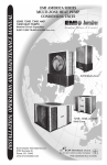
WLC/WLH
HIGH WALL EVAPORATOR
S p e c i f i c at i o n s a n d P e r f o r m a n c e
P/N 240005842, Rev. A [05/08]
• Operational range set point temperature
adjustable between 55°F and 90°F in one-degree
increments.
• Infra red compatible control allows use of optional
IR hand held controller
Note: Unit mounted controls are fully functional
without the handheld remote.
Straight Cool/Heat Pump*
Nominal Circuit Capacities: WLH 9,000, 12,000,
18,000, 24,000 Btuh and WLC (only) 30,000 & 36,000 Btuh
* Heat Pump only available for 9,000-24,000 Btuh units.
Product Description
The AmericaSeries WLC/WLH offers a contemporary
design, ductless type evaporator combining attractive
appearance in any decor and high efficiency conditioning for small to medium size commercial or residential
spaces. The WLC/WLH is equipped with unit mounted
infrared compatible controls which also supports 24V
remote wall thermostat operation. Optional hand held
remote is available.
Heat Pump models provide up to a nominal 24,000 Btuh
of cooling and heating. Electric heat options are available
for up to 5KW of supplemental heat.
This American-made evaporator offers ease of installation, operation, and service. It can be matched with
EMI’s S1C/S1H 09-24 and S1C 30-36 Btuh Single-Zone
Condensing Units, the S2C side discharge Multi-Zone
Condensing Unit, or the T2C, T3C, and T4C top discharge
Multi-Zone Condensing Units.
STANDARD FEATURES
Unit Mounted Control:
• Large LCD Backlit Display
• Single unit mounted control package, configurable
to either unit mount or remote wall thermostat
operation, reducing model number or SKU’s
required.
• Universal control can be used in cooling only,
cooling with electric heat, heat pump, or heat pump
with second stage electric heat applications.
Enviromaster International LLC
1
• Operation modes include Heat, Cool, Dry, Fan and
Auto Change-over.
• Fan Operation – Auto/On. High or Low speed fan
• Fan Purge – Fan remains on for 60 seconds after
Heat/Cool call is dropped for improved efficiency
(Auto mode only)
• Room air sampling: Selectable time intervals
ensures the fan will cycle on periodically, in Auto
Fan Mode.
Benefit: Helps to eliminate room temperature
stratification.
• Selectable Fahrenheit (°F) or Centigrade (°C)
temperature scale.
• Dry mode – Operates cooling and electric heat
simultaneously to remove humidity. Optional
electric heat must be selected.
• Anti-Short Cycle Compressor Protection.
• Minimum on time for heating and cooling.
Benefit: Helps eliminate room temperature drop
and system short cycling.
• Freeze Protection – Prevents evaporator freeze up.
• Test operation – Allows ease of testing after
installation (all timers are eliminated).
• Non-volatile back-up memory
Benefit: control settings are maintained for an
indefinite period during a power outage. When power
is restored the equipment will resume operation after
a three-minute compressor time delay.
• 7-day programmable with copy feature.
• Filter change indicator: A timer feature that
indicates the filter should be changed according to
the selected time.
• Motorized supply louver with optional sweep or
six stationary settings.
• Modular design – reduces parts required for control
Web: http://www.enviromaster.com
WLC/WLH Features and Optional Equipment
NOTE: Due to ongoing development programs, design and specifications may change without notice.
• Condensate drain pan constructed of galvanized steel
(G90U), with anti-corrosion coating.
• Modular snap-in, 7-day programmable control with
large backlit LCD display, a “Change filter” display
feature and selectable Fahrenheit (Fº), or Centigrade
(Cº) temperature scale.
• Operational range between 55ºF to 90ºF, adjustable
in one-degree increments.
STANDARD FEATURES Continued
package. Deco panel, relay board, ribbon cables and
microprocessor all combined into one package.
• Integral condensate pump safety-switch connection
where-by the microprocessor monitors the condensate
pump safety switch and displays an error code when
a fault occurs. (Applys only with optional condensate
pump)
• CEC (California Energy Commission) compliant
• Condensate drain pan over flow protection
Optional Equipment
• Condensate pump (field installed)
• 24V remote wall thermostat
• Electric heat with automatic reset high temperature
cutout and redundant high temperature fuse link
(when heat option is selected)
• hand held infrared controller.
Cabinet Features:
• Durable ABS plastic cabinet with a galvanized steel
sub-chassis.
• Easily accessible, washable, reusable, nylon mesh filter.
• Horizontal discharge louver, constructed of high
temperature ABS plastic, that can be set to oscillate,
or can be parked in various pre-set positions.
• Manually adjustable vertical discharge fins.
• Easy access to pipe chase area from cabinet bottom.
Installer Supplied Items
• Low voltage wiring
• Power wiring
• Mounting screws and fasteners
• Condensate piping
• Refrigerant piping (if not supplied)
• Refrigerant (for interconnect charge)
Benefit: allows piping connections and condensate
pump installation with the unit mounted on the wall.
• Easily removable end-cap for access to control area
for installation and service.
WLC/WLH Dimensions and Specifications
NOTE: Due to ongoing development programs, design and specifications may change without notice.
WLC/WLH
Shipping Weight
B
A
Model
lbs.
WLH09/12
70
WLH18/24
108
WLC30/36
TBD
C
WLC/WLH PHYSICAL DIMENSIONS
D
5 ¼”
“A”
“B”
“C”
WLH09
9 ⅞”
15 ¼”
38 ½”
24”
26 ½”
WLH12
9 ⅞”
15 ¼”
38 ½”
24”
26 ½”
WLH24
9 ⅞”
15 ¼”
48 ½”
34”
36 ½”
WLC30
9 ⅞”
15 ¼”
58 ½”
44”
46 ½”
WLC36
9 ⅞”
15 ¼”
58 ½”
44”
46 ½”
Model
1 ½”
2”
E
The Ductless Split System of Choice
4 ⅜”
2
“D”
“E”
Mounting
Tubing
Depth Height Length Bracket
Access
Clearance Clearance
Made in Rome, New York, USA
WLC/WLH Specifications
NOTE: Due to ongoing development programs, design and specifications may change without notice.
WLC/WLH ELECTRICAL SPECIFICATIONS
MODEL #
VOLTS/HZ/PH
FAN
RLA
115/60/1
0.64
0.02
–
115/60/1
0.64
0.02
0.75
208/230/60/1
0.34
0.02
–
–
0.34
208/230/60/1
0.34
0.02
3.00
13.04
13.38
115/60/1
1.20
1.20
104
HP
HEATER
K.W.
TOTAL
AMPS
MIN
VOLT
M.C.A.
HACR
BRKR
–
0.64
104
0.8
15
6.50
7.14
104
8.9
15
197
0.4
15
197
16.7
20
1.5
15
AMPS
SMALL CABINET 09/12
09/12
MEDIUM CABINET 18/24
24
0.083
–
–
115/60/1
1.20
0.083
0.75
6.52
7.72
104
9.7
15
115/60/1
1.20
0.083
1.25
10.90
12.10
104
15.1
20
208/230/60/1
0.56
0.070
–
–
0.56
197
0.7
15
208/230/60/1
0.56
0.070
3.00
13.04
13.60
197
17.0
20
208/230/60/1
0.56
0.070
5.00
21.74
22.30
197
27.9
30
208/230/60/1
0.80
1/10
–
–
0.80
197
1.0
15
208/230/60/1
0.80
1/10
5.00
21.74
22.54
197
28.2
30
LARGE CABINET 30/36
30/36
WLC/WLH Interconnecting-Line Size
DISCHARGE AIR SPEED AND FLOW @ 230V
Model High CFM
9/12
18/24
30/36
Low CFM Coil
400
750
1,170
350
675
900
Dry
Dry
Dry
FPM
Throw/Ft.
900
1,225
1,250
15
25
27
WLC/WLH OBSERVED SOUND VALUES
(230V High Speed Fan)
System Capacity
Btuh
09
12
18
24
30
36
Liquid
O.D.
1/4”
1/4”
3/8”
3/8”
3/8”
3/8”
Suction
O.D.
1/2”
1/2”
5/8” *
3/4”
3/4” **
3/4” **
Condensate
I.D.
1/2”
1/2”
1/2”
1/2”
1/2”
1/2”
Model
dBA
09/12
45
* WLC/WLH Suction Connection size is 3/4” O.D. and must bush down at the
18/24
56
** WLC/WLH Suction Connection size is 5/8” O.D. a factory supplied kit is provided
30/36
60
WLC/WLH Unit.
to transition to 3/4” O.D. interconnect.
WLC/WLH System Options
Cooling Systems with Wall Units
Condenser
Wall Unit
Btuh
SEER
SHR
EER
Ref.
S1C9
WLH09
9,000
13.0
.79
11.8
R22
S1C2
WLH12
12,000
13.0
.74
12.9
R22
S1C8
WLH24
18,000
14.0
.78
13.0
R22
S1C4
WLH24
24,000
13.0
.70
12.5
R22
S1C3
WLC36
30,000
13.0
.72
12.6
R22
S1C6
WLC36
33,600
13.0
.69
12.1
R22
*
WLC/wlh
* Important - This system has been designed and manufactured to meet
ENERGY STAR criteria for energy efficiency. However, proper refrigerant charge and proper air flow are critical to achieve rated capacity and
efficiency. Installation of this product should follow the manufacturer’s
Heat pumps System Options with Wall Units
refrigerant charging and air flow inWall Unit Cooling Btuh Heating Btuh SEER HSPF SHR EER COP Ref.
structions. Failure to
WLH09
9,000
8,600
13.0
8.0
.75 11.6
3.6 R22
confirm proper charge
and airflow may reduce
WLH12
11,400
10,600
13.0
8.0
.73
11.5
3.4 R22
energy efficiency and
WLH24
18,000
16,400
13.0
7.7
.73
12.1 3.8 R22
shorten equipment life.
S1C/S1H
Condenser
S1H9
S1H2
S1H8
S1H4
WLH24
23,000
Enviromaster International LLC
20,600
13.0
8.3
3
.71
11.9
3.5
R22
Web: http://www.enviromaster.com
WLC/WLH System Options
NOTE: Due to ongoing development programs, design and specifications may change without notice.
S2C
Side Discharge
T2C, T3C & T4C
Top Discharge
WLC
Cooling Systems with S2C Side discharge
Wall Unit (s)
Condenser
Btuh
SEER
SHR
EER
Ref.
WLH09
S2C99
18,000
13
WLH12
S2C22
23,000
13
.80
11.9
R22
.72
12.4
WLH09+WLH12
S2C92
21,000
13
R22
.72
12.0
R22
System Options with T2C TOP discharge
Wall Unit(s)
Condenser
Btuh
SEER
SHR
EER
Ref.
WLH24
T2C88
36,000
13
.79
12.1
R22
WLH24
T2C44
45,000
13
.73
11.8
R22
WLH09+WLH24
T2C98
27,000
13
.80
11.8
R22
WLH24
T2C84
41,000
13
.76
11.8
R22
WLH12+WLH24
T2C24
34,000
13
.72
11.8
R22
System Options with T3C TOP discharge
Wall Unit(s)
Condenser
Btuh
SEER
SHR
EER
Ref.
WLH09+WLH24
T3C994
41,000
13
.77
11.9
R22
WLH09
T3C999
27,000
13
.80
11.7
R22
WLH12
T3C222
34,000
13
.71
11.7
R22
WLH09A+WLH24
T3C928
39,000
13
.77
11.9
R22
WLH09+WLH12+WLH24
T3C924
43,000
13
.75
11.8
R22
WLH12+WLH24
T3C228
41,000
13
.74
11.8
R22
WLH09+WLH12
T3C922
32,000
13
.74
11.8
R22
WLH09+WLH12
T3C992
30,000
13
.77
11.9
R22
WLH09+WLH24
T3C998
36,000
13
.80
11.8
R22
WLH12+WLH24
T3C224
46,000
13
.72
11.7
R22
System Options with T4C TOP discharge
Phone: 1-800-228-9364
Fax: 1-800-232-9364
Wall Unit(s)
Condenser
Btuh
SEER
SHR
EER
Ref.
WLH09
T4C9999
36,000
13
.80
11.8
R22
WLH12
T4C2222
45,000
13
.73
11.7
R22
WLH09+WLH12
T4C9222
42,000
13
.71
11.8
R22
WLH09+WLH12
T4C9992
38,000
13
.71
11.8
R22
WLH09+WLH12
T4C9922
41,000
13
.73
11.9
R22
5780 Success Drive,
Rome, NY 13440