1
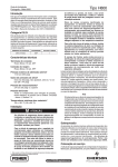
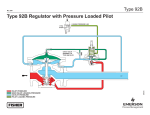
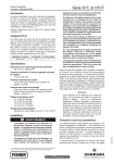
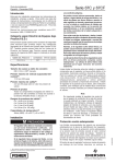
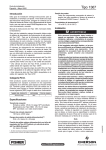
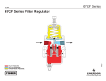
Type H800
Instruction Manual
Form 5187
March 2009
Type H800 Relief Valve
!
Warning
Failure to follow these instructions or to
properly install and maintain this equipment
could result in an explosion, fire and/or
chemical contamination causing property
damage and personal injury or death.
Fisher® relief valves must be installed, operated
and maintained in accordance with federal,
state, and local codes, rules and regulations,
and manufacturer’s instructions.
If a leak develops or if the outlet continually
vents gas, service to the unit may be required.
Failure to correct trouble could result in a
hazardous condition. Only a qualified person
must install or service the unit
Installation, operation, and maintenance
procedures performed by unqualified personnel
may result in improper adjustment and unsafe
operation. Either condition may result in
equipment damage or personal injury. Use
qualified personnel when installing, operating,
and maintaining the Type H800 relief valve.
Introduction
W3618
Figure 1. Type H800 Relief Valve
Specifications
Specifications for the Type H800 relief valve are given on
page 2. Additional specifications for 67 Series regulators used
with Type H800 relief valves are shown in Table 1.
Installation
Upon receipt, inspect the relief valve to be sure it is free of
foreign material.
This manual provides installation, maintenance, and parts
ordering information for the Type H800 relief valve. Information
for other equipment used with this relief valve is contained in
separate manuals.
Product Description
The Type H800 relief valve(1) (See Figure 1) is a compact,
Direct-Operated relief valve. It is used primarily between a
pneumatic instrument and its supply pressure regulator to limit
the instrument supply pressure to 50 psig (3,4 bar) should
the supply pressure regulator fail open. The Type H800 relief
valve can also be mounted on other equipment, such as an air
compressor, where limited relief capacity is desired.
!
Warning
Installing a Type H800 relief valve where its
capabilities can be exceeded or where proper
operation might be impaired may cause
personal injury, property damage, or leakage
due to bursting of pressure-containing parts or
explosion of accumulated gas. To avoid such
conditions, install a Type H800 relief valve where:
• Service conditions are within the unit
capabilities are specified in specifications
section and Table 1, and
• The relief valve is protected from
exposure to physical damage and/or
corrosive substances.
1. Relief valve defined in ANSI Standard B95.1-1972. Not all codes or regulations permit these valves to be used as final overpressure protection devices.
www.emersonprocess.com/regulators
D100405X012
Scope of the Manual
Type H800
Specifications
Body Size and End Connection Style
NPS 1/4, NPT (internal)
Maximum Temperature Capabilities(1)
-20° to 150°F (-29° to 66°C)
Maximum Allowable Inlet (Relief) Pressure(1)
250 psig (17,2 bar)
IEC Sizing Coefficients
Relief Pressure Ranges
Non-adjustable, Start-to-discharge between
39 and 44 psig (2,7 and 3,0 bar)
Reseat Pressure(1)
35 psig (2,4 bar) or higher
Wide-Open Flow Coefficients for Relief Valve Sizing
XT: 0.775
FD: 0.50
FL: 0.89
Vent Connection
1/2 NPT (internal)
Approximate Weight
5 ounces (140 grams)
Cg: 55
1. The pressure/temperature limits in this Instruction Manual or any applicable standard limitation should not be exceeded.
Table 1. Maximum Allowable Inlet Pressure to 67 Series Regulators (with Type H800 Relief Valve)
to Prevent Instrument Supply Pressure from Exceeding 50 psig (3,4 bar)
type h800 installations
from figure 2
A
supply pressure
regulator Types
67, 67R, 67R, 67FR,
67CF, or 67CFR
67, 67R, 67CF, or 67CFR
B
67FR or 67F
remote
vent piping(1)
Yes
No
Yes
No
Yes
No
maximum allowable inlet pressure to
supply pressure regulator, psig (bar)
250
(17,2)
100
250
100
200
(6,9)
(17,2)
(6,9)
(13,8)
1. Limit vent piping to 30 equivalent feet (9,14 equivalent meters) of 1/2-inch (13 mm) piping. Lower vent piping may reduce the maximum allowable inlet pressure to supply
pressure regulator.
The relief valve may be shipped already mounted on other
equipment; if so, install that equipment by referring to its
Instruction Manual.
!
Warning
This relief valve vents gas from the connection
marked “vent”. In hazardous or flammable
gas service, the vented gas may accumulate,
causing personal injury or equipment damage
due to fire or explosion. Provide piping or
tubing to vent the gas to a safe, well-ventilated
location, and protect all vent openings from
condensation, freezing, or any substance that
could clog the vents.
The 1/2 NPT vent connection must face down in any installation.
Also, the screen (key 7) and disk restriction (key 6) must either
remain in the relief valve body (key 1) or be replaced by remote
vent piping or tubing that is as short and as straight as practical.
The piping or tubing should be 1/2-inch (13 mm) in diameter to
avoid the effects of backpressure build-up on relief performance.
Provide a screened vent for the open end of the remote vent
piping or tubing.
Figure 2 illustrates two typical methods of connecting a Type H800
relief valve to a 67 Series regulator. A yoke-mounted supply
pressure regulator and pneumatic instrument are shown in
2
Figure 2; however, the two methods of connecting a Type H800
relief valve to a 67 Series regulator also apply to pneumatic
instruments mounted on other equipment in other orientations.
Table 1 lists the conditions for the two typical methods of
installing a Type H800 relief valve. Whenever possible, use
installation A since a Type H800 relief valve with or without
remote vent piping will limit instrument supply pressure to 50 psig
(3,4 bar) when a 67 Series regulator fails open with 250 psig
(17,2 bar) inlet pressure.
For installation A, install the relief valve in the instrument
supply tubing between the supply pressure regulator and the
pneumatic instrument. Apply pipe compound to the male
threads of the pipe nipple and the fitting for the instrument
supply pressure tubing.
For installation B, connect the relief valve with a pipe nipple to
the outlet pressure gauge connection of the 67 Series regulator.
Install a pipe plug or pressure gauge as shown in Figure 2. Apply
pipe compound to the male threads of the pipe nipple and pipe
plug or pressure gauge.
Maintenance
Relief valve parts are subject to normal wear and must be
inspected and replaced as necessary. The frequency of inspection
and parts replacement depends on the severity of service
conditions and the requirements of local, state, and federal rules
and regulations.
Type H800
PNEUMATIC
INSTRUMENT
ACTUATOR YOKE
TYPE 67AFR
REGULATOR
TYPE H800
RELIEF VALVE
INLET PRESSURE
TUBING
TUBING FOR
INSTRUMENT
SUPPLY PRESSURE
VENT CONNECTION
ACTUATOR YOKE
W3615
INSTALLATION A
ACTUATOR YOKE
TYPE 67AFR
REGULATOR
PNEUMATIC
INSTRUMENT
TYPE H800
RELIEF VALVE
PIPE PLUG (MAY ALSO BE
OPTIONAL GAUGE)
INLET PRESSURE
TUBING
VENT
CONNECTION
TUBING FOR
INSTRUMENT
SUPPLY PRESSURE
W3616
INSTALLATION B
Figure 2. Typical Installation Orientations
The relief valve body may remain installed during maintenance or
inspection unless it is to be replaced. Instructions are given below
for disassembly and assembly of parts.
!
Warning
To avoid personal injury or equipment
damage from sudden release of pressure or
explosion of accumulated gas, do not attempt
any maintenance or disassembly without
first isolating the relief valve and associated
equipment from system pressure and relieving
all internal pressure from the relief valve and
associated equipment.
Disassembly
The following procedure describes the complete disassembly of
the Type H800 relief valve. When parts replacement or inspection
is required, complete only those steps necessary to accomplish
the job. Key numbers refer to Figure 3.
1. Vent any pressure in the relief valve.
2. Unscrew the machine screws (key 9), and remove
the spring case (key 2).
3. Remove the spring (key 3), spring cup (key 4),
diaphragm disk (key 11), and diaphragm (key 5).
4. If necessary, remove the retaining ring (key 8), the
screen (key 7), and disk restriction (key 6).
Assembly
This procedure describes complete assembly. If the relief valve
has been only partially disassembled, start these instructions at
the appropriate step. Key numbers refer to Figure 3.
1. Insert the diaphragm (key 5) so that the raised,
circular ridge faces toward the spring cup (key 4) as shown
in Figure 3.
2. Slide the spring (key 3) into the spring cup (key 4).
3. Place the diaphragm disk (key 11), spring cup, and spring
on the diaphragm. Orient the diaphragm disk so that its
raised, circular lip faces toward the spring cup as shown
in Figure 3.
4. Position the spring case (key 2) on the body (key 1). Insert
and tighten the machine screws (key 9).
5. Insert the disk restriction (key 6), screen (key 7), and
retaining ring (key 8).
3
Type H800
Parts Ordering
When ordering replacement parts for a Type H800 relief
valve, refer to the following parts list, and specify the complete
11-character part number of each needed part.
Parts List
Key Description
1 Relief Valve Body, Aluminum 2 Spring Case, Aluminum 3 Spring, Steel 4* Spring Cap, Valox® 730 plastic 5* Diaphragm, Nitrile (NBR)
6 Disk Restriction, 302 Stainless steel 7 Screen, 304 Stainless steel 8 Internal Retaining Ring, Plated steel 9 Machine Screw, Plated steel (2 required)
10 Pipe Nipple (not shown), for use in
installation B, Galvanized steel 11 Diaphragm Disk, Plated steel 2
3
9
4
1
11
5
Part Number
26A9050X012
26A9051X012
16A9052X012
26A9053X012
16A9054X012
16A9055X012
16A9056X012
16A9057X012
1B7839X0012
1/4 NPT
1/4 NPT
7
6
8
1C678926232
17A7753X012
1/2 NPT Vent
26A9059-B
A2908
*Recommended spare part.
Valox® 730 is a mark owned by General Electric Co.
Figure 3. Type H800 Relief Valve Assembly
Industrial Regulators
Natural Gas Technologies
TESCOM
Emerson Process Management
Regulator Technologies, Inc.
Emerson Process Management
Regulator Technologies, Inc.
Emerson Process Management
Tescom Corporation
USA - Headquarters
McKinney, Texas 75069-1872 USA
Tel: 1-800-558-5853
Outside U.S. 1-972-548-3574
USA - Headquarters
McKinney, Texas 75069-1872 USA
Tel: 1-800-558-5853
Outside U.S. 1-972-548-3574
USA - Headquarters
Elk River, Minnesota 55330-2445 USA
Tel: 1-763-241-3238
Asia-Pacific
Shanghai, China 201206
Tel: +86 21 2892 9000
Asia-Pacific
Singapore, Singapore 128461
Tel: +65 6777 8211
Europe
Bologna, Italy 40013
Tel: +39 051 4190611
Europe
Bologna, Italy 40013
Tel: +39 051 4190611
Gallardon, France 28320
Tel: +33 (0)2 37 33 47 00
Middle East and Africa
Dubai, United Arab Emirates
Tel: +971 4811 8100
Europe
Selmsdorf, Germany 23923
Tel: +49 (0) 38823 31 0
For further information visit www.emersonprocess.com/regulators
The Emerson logo is a trademark and service mark of Emerson Electric Co. All other marks are the property of their prospective owners. Fisher is a mark owned by Fisher Controls, Inc., a
business of Emerson Process Management.
The contents of this publication are presented for informational purposes only, and while every effort has been made to ensure their accuracy, they are not to be construed as warranties or
guarantees, express or implied, regarding the products or services described herein or their use or applicability. We reserve the right to modify or improve the designs or specifications of such
products at any time without notice.
Emerson Process Management does not assume responsibility for the selection, use or maintenance of any product. Responsibility for proper selection, use and maintenance of any Emerson
Process Management product remains solely with the purchaser.
©Emerson Process Management Regulator Technologies, Inc., 1982, 2009; All Rights Reserved