1
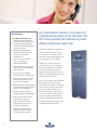
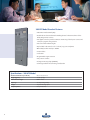
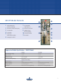
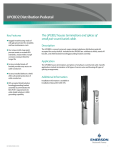
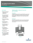
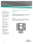
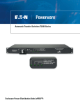
Outside Plant for
Business-Critical Continuity™
NetXtend™ PDC Series with NTI Technology
Integrated Enclosure Solution
Key Features
V3 SHIELD™ NTI Technology —
adds thermal protection at the
“board level” eliminating thermal
runaway and allows actual peak
pulse current to be handled by the
suppression module
n
Integrated design minimizes
“footprint,” maximizes system
performance and reduces
installation time
n
30 or 42-position load center
options provide wiring
configuration flexibility
n
Fully redundant, two-stage surge
suppression provides unmatched
power protection
n
Easy access design simplifies
module upgrades or replacement
n
Main disconnect switch for utility
and optional generator sources
allows easy serviceability
As a stand-alone solution, or as part of a
comprehensive power protection plan, the
PDC series provides the ultimate in power
delivery and power protection.
The NetXtend™ PDC Series of integrated
enclosures offers both power distribution and TVSS in one seamless unit. An
Automatic Transfer Switch (ATS) for generator applications is also available.
The PDC Series provides the lowest
possible clamp voltage to peak current
performance characteristics available
in the market today. Integrated V3
SHIELD™ NTI technology provides peak
pulse current handling that surpasses traditional “fused TVSS” devices.
n
Optional Automatic Transfer Switch
or Slide Bar Transfer Switch provides
generator source capabilities
n
SAD technology provides fast
clamping and high energy handling
n
Remote status indication allows
long-distance monitoring
n
Field replaceable modules are
stacked side-by-side for easier
installation and indication
n
Independent visual LED status
indication on each module for
convenient protection status
n
2
This series also utlizizes Silicon Avalanche
Diode (SAD) technology, providing
state-of-the-art protection at the branch
service entrance. The 30 or 42-position
load center enables the PDC series to
accommodate a broad range of wiring
options. The main disconnect allows convenient serviceability and maintenance.
Generator switching is accommodated
with either an Automatic Transfer Switch
or Walking Beam Transfer Switch.
Protection against destructive weather,
thermal, electrical, environmental and
mechanical forces is vital to assuring the
reliability and revenue-producing capability
of your wireless and wireline networks
Ordering Matrix – NetXtend™ PDC Series
Service Voltage
B = 120/240V, single phase
Primary Suppression
2 = SAD 20 kA
TVSS Configuration
K = Kelvin (in-line)
Supplemental Suppression
B = MOV 200 kA
B = MOV 200 kA
0 = None
Amperage
2 = 200 Amp
Load Center
3 = 30 overcurrent devices
Disconnect
Grounding Options
Voltage Monitoring
4 = 42 overcurrent devices
B = Single disconnect, 65 kAIC
W = Walking beam (discontinued)
U = 300 ATS Series (Automatic Transfer Switch)
S = Slide bar interlock (standard)
G = Isolated ground
S = Standard ground
Q = Normal/Generator
Specifications – PDC Model
AC Cabinet Dimensions
20.00" wide x 65.00" high x 5.75" deep
Weight
Approx. 75 lbs. (50 kg)
Cabinet Enclosure Type
NEMA 1 rated
Amperage
200 Amp utility/standby
Safety Compliance
UL 67 Panelboards
UL 65k AIC standard, slide bar PDC
NOTE: All PDC cabinets are available with up to 65k AIC ratings.
Suppression Module Specifications – PDC Model
Primary
Secondary
Nominal Clamp Voltage
232 Vpk
272 Vpk
Response Time
< 5 ns
< 20 ns
Peak Pulse Energy
up to 800 Joules
> 1920 Joules
Peak Pulse Current (8x20µs)
up to 20 kA
200 kA
Primary and Secondary
Visual Indication
LEDs
Remote Indication
Hardwired (form C dry contacts)
Safety Compliance
UL 1449 recognized
Protection
Overcurrent & overvoltage (thermal)
3
300 ATS Model Standard Features
•Automatic Transfer Switch (ATS)
•Double-throw electromechanical switching device for inherent isolation of the
utility and generator sources.
•ATS digital controller provides continuous monitoring of both power sources and
a start/stop signal to the generator
•ATS control with indication lights
•Key-lockable load center door for “lock-out / tag-out” compliance
•Main utility breaker rated up to 65kAIC
•TVSS modules
•Load center
•Programmable engine exerciser
•ATS position contacts
•Voltage monitoring relays (240VAC)
•Isolated ground bar and common ground bus bar
Specifications – 300 ATS Model
4
AC Cabinet Dimensions (H x W x D)
68.00" x 25.50" x 6.00"
Weight (approx.)
110 lbs. (50 kg)
Cabinet Enclosure Type
NEMA 1 rated
Amperage
200 Amp utility/standby
Voltage
120/240 VAC single phase
Safety Compliance
UL 67 panel boards
300 ATS Model Elements
1
5
6
1
Utility Main Breaker
(rated up to 65kAIC)
7
Programmable
Engine Exerciser
2
3
4
5
Automatic Transfer Switch (ATS)
8
9
ATS Position Contacts
6
ATS Digital Controller
TVSS Modules
Load Center
ATS Control
(with indication lights)
240VAC Voltage
Monitoring Relays
10 Isolated Ground Bar
11Ground Bar
2
7
3
8
9
10
4
11
Suppression Module Specifications – 300 ATS Model
Primary
Secondary
Nominal Clamp Voltage
232 Vpk
272 Vpk
Response Time
< 5 ns
< 20 ns
Peak Pulse Energy
up to 800 Joules
> 1920 Joules
Peak Pulse Current (8x20µs)
up to 20 kA
200 kA
Primary and Secondary
Visual Indication
LEDs
LEDs
Remote Indication
Hardwired (form C dry contacts)
Hardwired (form C dry contacts)
Safety Compliance
UL 1449 recognized
UL 1449 recognized
Protection
Overcurrent & overvoltage (thermal)
Overcurrent & overvoltage (thermal)
5
Transfer Switch Specifications
Poles
2
Voltage (nominal)
220-240 VAC, single phase, 3 wire
Frequency (nominal)
60 Hz
Current
200 Amps
Generator Rating (maximum)
48KW
Withstand / Close-On Current
10,000 Amps
RMS Symmetrical amps 240 VAC max.
for any circuit breaker, manufacturer, or
type per National Electrical Code, NEC/NFPA 70
Power Terminal Wire Sizes
200 Amp unit
One #8 to 3/0 AWG Cu
(copper wire must be used for full 200 Amp rating)
Safety Compliance
UL 1008 transfer switch equipment
Controller
The NetXtend™ PDC Series incorporates
several parameters that can be set
according to system design preferences.
This allows for a wide range of flexibility
in setting thresholds and timing options
with the standard base product. The
standard controller utilizes simple push
button operation for testing and exerciser time set.
6
Voltage and Frequency Sensing
Differential Voltage Sensing
All phases of utility source
Voltage (Nominal)
220-240 VAC
Normal Source Voltage Drop Out
204 VAC
Normal Source Pick Up
216 VAC
Emergency Source Voltage Drop Out
180 VAC
Emergency Source Voltage Pick Up
216 VAC
Emergency Source Frequency Drop Out
51 VAC
Emergency Source Frequency Pick Up
57 VAC
Emerson Network Power
provides a complete range of communications
network infrastructure solutions and services
built on an industry-leading reputation for
quality, reliability and value
Generator Exercise Control
Transformer
Voltage Adjust
Standard Automatic Generator Exerciser
Repeat Time
Every 7 days
Duration
20 minutes – with or without load transfer
Generator Control Contacts
Gold plated engine start/stop contacts
HI
Nominal phase-to-phase voltage
LOW Shifts all voltage settings
down 4.2% from nominal
Rated 5 Amps 28 VDC / 120 VAC
Time Delay Parameters and Control
Override Momentary Normal Source Outage
3 seconds
Transfer to Generator Time Delay
0-5 minutes adjustable
Override Momentary Generator Initial Loading Events
4 seconds
Re-transfer to Normal Source Time Delay
1 second to 30 minutes adjustable
Unloaded Generator Cool Down Run Time Delay
5 minutes
Optional Programmable
Engine Exerciser
In addition to the standard programmable weekly exercise function, an optional
programmable controller provides the
ability to individually control the start
time and duration of test for each day
of the week. An internal NiCad battery
retains program memory for up to 150
hours if failure of both utility and generator power occurs.
Remote Control Features
Communications Option
• Remote test switch
Simulates normal source failure similar
to a transfer switch test push button
Remote monitoring and control can also
be provided through additional networking software and interface hardware
options, including web access capability.
• Remote transfer to generator
Opening the contact causes the
generator to start and transfer to the
generator
NOTE: These enhancements are not included
with the standard product.
• Inhibit transfer to generator
Opening the contact prevents the
transfer switch from transferring to the
generator source while connected to
the normal source
• Remote time delay bypass switch
NOTE: Requires customer supplied, remote
normally closed contact and control signaling
for each remote feature desired. See manufacturer reference drawings and manual for
additional details.
7
Emerson (NYSE: EMR), based in St. Louis, Missouri (USA), is a global leader in bringing technology and engineering
together to create innovative solutions for customers through its network power, process management, industrial
automation, climate technologies, and appliance and tools businesses. For more information, visit: Emerson.com.
Emerson Network Power, a business of Emerson (NYSE:EMR), is the global leader in enabling Business-Critical Continuity™
from grid to chip for telecommunication networks, data centers, health care and industrial facilities. Emerson Network
Power provides innovative solutions and expertise in areas including AC and DC power and precision cooling systems,
embedded computing and power, integrated racks and enclosures, power switching and controls, monitoring, and
connectivity. All solutions are supported globally by local Emerson Network Power service technicians. For more
information on Emerson Network Power’s full suite of solutions specifically supporting the communications network
infrastructure, including NetSpan™, NetReach™ and NetXtend™ outside plant enclosures and equipment, NetSure™ DC
power systems, and turnkey services, visit: EmersonNetworkPower.com/EnergySystems.
Learn more about Emerson Network Power products and services at: EmersonNetworkPower.com.
This publication is issued to provide outline information only which (unless agreed by Emerson Network Power Energy Systems, North America, Inc. in writing) may not be
used, applied or reproduced for any purpose or form part of any order or contract or be regarded as a representation relating to the products or services concerned. Emerson
Network Power Energy Systems, North America, Inc. reserves the right to alter without notice the specification, design or conditions of supply of any product or service.
Emerson®, Emerson Network Power™, Business-Critical Continuity™, NetSpan™, NetReach™, NetXtend™ and NetSure™ are trademarks of Emerson Electric Co. and/or
one of its subsidiaries.
Emerson Network Power
Energy Systems, World Headquarters
4350 Weaver Parkway, Warrenville, IL 60555 USA
Toll Free: 800-800-1280 (USA and Canada)
Telephone: 440-246-6999 Fax: 440-246-4876
Web: EmersonNetworkPower.com/EnergySystems
Emerson Network Power.
The global leader in enabling Business-Critical Continuity™.
AC Power
Connectivity
DC Power
Embedded Computing
Embedded Power
Monitoring
EmersonNetworkPower.com
Outside Plant
Power Switching & Controls
Precision Cooling
Racks & Integrated Cabinets
Services
Surge Protection
© 2009 Emerson Network Power Energy Systems, North America, Inc. All rights reserved.
Code: OSP-128400
May 2009