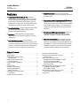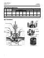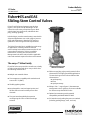
1
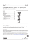
Product Bulletin ES Valve 51.1:ES December 2012 D100021X012 Fisherr ES and EAS Sliding-Stem Control Valves Fisher ES and EAS general-purpose control valves (figures 1 and 2) are used for throttling or on-off control of a wide variety of liquids and gases. Both valve designs have single ports, unbalanced valve plugs, and cage guiding. In both designs, metal-to-metal seating is standard for all general applications over a wide range of pressure drops and temperatures. Metal-to-PTFE seating is optional for more stringent shutoff requirements. The Fisher ES product line is available for a wide range of applications, including sulfide and chloride stress-cracking environments common to the oil and gas production industries. To discuss available constructions, contact your Emerson Process Management sales office and include the applicable codes and standards required for these environments. The easy-e™ Valve Family W2174-1 FISHER ES CONTROL VALVE WITH 657 ACTUATOR ES and EAS valves are part of the versatile easy-e family of Fisher industrial control valves. easy-e valves share the following characteristics. Multiple trim material choices Trim temperature capability with standard metal seats to 427_C (800_F) Flexible graphite gaskets Interchangeable, restricted-capacity trims and full-flow trims to match variable process flow demands Trim part interchangeability that permits reconfiguring the valve to a different design variation www.Fisher.com Different cage/plug styles provide particular flow characteristics for highly-specialized applications. The standard cage comes in three different flow characteristics: quick-opening linear equal percentage Whisper Trimt I cages (figure 1) that attenuate aerodynamic noise in gaseous service are available for all sizes except the NPS 8 ES valve. Optional constructions provide material compatibility with NACE MR0175-2002. 316 stainless steel packing box parts are standard (including packing flange, studs, and nuts). Product Bulletin ES Valve 51.1:ES December 2012 D100021X012 Features Compliance with the Clean Air Act– Optional ENVIRO-SEAL™ packing systems (figure 3) provide an improved stem seal to help prevent the loss of process fluid. The ENVIRO-SEAL packing systems feature PTFE, Graphite ULF, or Duplex packing with live-loading for reduced packing maintenance. Valve Plug Stability– Rugged cage guiding provides increased valve plug stability, which reduces vibration and mechanical noise. Economy– Streamlined flow passages provide higher efficiency and greater capacities per initial investment. Cost-Effective Operation– Increased wear resistance of the standard hardened stainless steel trim means long-lasting service. Also, trim inventory costs are cut because dimensional standardization permits use of most standard easy-e trim parts. Easy Maintenance– The valve can stay in the pipeline during removal of trim parts for inspection or maintenance. Long-Lasting Shutoff Capability with PTFE Seating– Controlled compression of optional seat construction protects PTFE disk between metal disk seat and disk retainer (figure 1). The flowstream contacts only the edge of the disk during normal operation. Compliance with European Standards– Valves are available with dimensions specified by EN/DIN standards. See figure 7 and the note in figure 8. Sour Service Capability– Unless otherwise noted, references are to NACE MR0175-2002. Optional materials are available to meet NACE MR0103 and NACE MR0175 / ISO15156. Material requirements under these standards vary by edition and year of issue; the specific standard must be specified. Table of Contents Features . . . . . . . . . . . . . . . . . . . . . . . . . . . . . . . . . . . . . Specifications . . . . . . . . . . . . . . . . . . . . . . . . . . . . . . . . ENVIRO-SEAL Packing System Specifications . . . . . . . . . . . . . . . . . . . . . . . . . . . . . . ENVIRO-SEAL and HIGH-SEAL Packing Systems . . . . . . . . . . . . . . . . . . . . . . . . . . . Class VI Shutoff Capabilities . . . . . . . . . . . . . . . . . . . . Tables Class VI Tables . . . . . . . . . . . . . . . . . . . . . . . . . . . . . . . . Available Constructions . . . . . . . . . . . . . . . . . . . . . . . . Typical Combinations of Metal Trim Parts . . . . . . . . . . . . . . . . . . . . . . . . . . . . Valve Body/Trim Temperature Capabilities . . . . . . . . . . . . . . . . . . . . . . . . . . . . . . . . Bonnet Selection Guidelines . . . . . . . . . . . . . . . . . . . . 2 2 3 4 5 5 5 6 7 9 9 Maximum Flow Coefficients . . . . . . . . . . . . . . . . . . . Materials and Temperature Limits for All Other Parts . . . . . . . . . . . . . . . . . . . . . . . . . . . . Metal Trim Part Materials for Compatibility with NACE MR0175-2002 (Sour Service) Specifications, Environmental Restrictions Apply, Refer to Standard . . . . . . . . . . . . . . . . . . . . . . . . . . Bolting Materials and Temperature Limits for Bolting Compliance with NACE MR0175-2002 . . . . . . . . . . . . . . . . . . . . . . . Port Diameters, Valve Plug Travel, and Stem and Yoke Boss Diameters . . . . . . . . . . . . . . Dimensions . . . . . . . . . . . . . . . . . . . . . . . . . . . . . . . . . 11 12 13 15 15 17 Product Bulletin ES Valve 51.1:ES December 2012 D100021X012 Specifications Available Configurations Construction Materials Body, Bonnet, and Bonnet Spacer or Bottom Flange, if used: J WCC carbon steel,J CF8M stainless steel, J LCC carbon steel, J WC9 chrome moly steel; J Cast iron body with steel bonnet construction J Other material constructions upon request Valve Plug, Cage, and Metal Seating Parts: See table 4 All Other Parts: See table 9 ES: Single-port, globe-style control valve with cage guiding, unbalanced valve plug, and push-down-to-close valve plug action (figure 1) EAS: Angle version of ES control valve, used to facilitate piping or in applications where a self-draining valve is desired (figure 2) Valve Sizes See table 3 Material Temperature Capabilities(2) Body/Trim Combinations: See tables 4 and 6 Those For NACE Specification: See tables 10 and 11 All Other Parts: See table 9 End Connection Styles(1)(2) Cast Iron Valves Flanged: ES, NPS 1 through 8, including NPS 1-1/2 and 2-1/2 (except NPS 1-1/4), J CL125 flat-face or J CL250 raised-face flanges per ASME B16.1 Steel and Stainless Steel Valves Flanged: J CL150, 300, or 600 raised-face (RF) or ring-type joint (RTJ) flanges per ASME B16.5, J Raised-face (RF) flanges per EN1092-1/B Screwed or Socket Welding: NPS 1/2 through 2, consistent with ASME B16.11 Buttwelding: NPS 1 through 8 (except NPS 1-1/4). Schedules 40 or 80 consistent with ASME B16.25 Flow Characteristics Standard Cages: J Quick-opening, J linear, or J equal percentage Whisper Trim: Linear Flow Directions ES Standard Cage: Normally up Whisper Trim Cages: Always up EAS Standard Cage: Without liner, flow up or down; with liner, normally down Whisper Trim Cages: Always up Maximum Inlet Pressures and Temperatures(1)(2) As listed below, unless limited by maximum pressure drop or material temperature capabilities Cast Iron Valves Flanged: Consistent with CL125B or 250B per ASME B16.1 Steel and Stainless Steel Valves Flanged: Consistent with CL150, 300, and 600(3) per ASME B16.34 Screwed or Welding: Consistent with flanged CL600(3) per ASME B16.34 Flow Coefficients and Noise Level Prediction See table 8 and Catalog 12 Port Diameters and Maximum Valve Plug Travels See table 12 Yoke Boss and Stem Diameters See table 12 Maximum Pressure Drop(2) Same as maximum inlet pressure for specific construction defined above, except where further limited as shown in figures 5 and 6 Valves for NACE MR0175-2002: See figure 5 Typical Bonnet Styles J Plain or J extension. See figures 7 and 8 for standard dimensions. See table 7 for selection guidelines Shutoff Classifications per ANSI/FCI 70-2 and IEC 60534-4 J ENVIRO-SEAL bellows seal bonnet. See figure 4 for view of ENVIRO-SEAL bellows seal bonnet. Also, see Bulletin 59.1:070, ENVIRO-SEAL Bellows Seal Bonnets, for further information Metal Seating: Class IV is standard. Class V is optional PTFE Composition Seating: Class VI - continued - 3 Product Bulletin ES Valve 51.1:ES December 2012 D100021X012 Specifications (continued) Packing Arrangements Standard Material: Single PTFE V-ring ENVIRO-SEAL Packing: See figure 3 ENVIRO-SEAL Packing Systems in vacuum service: Standard ENVIRO-SEAL packing systems can be used in vacuum service with packing rings in standard orientation. Do not reverse the ENVIRO-SEAL PTFE packing rings. Also see Bulletin 59.1:061, ENVIRO-SEAL Packing Systems for Sliding-Stem Valves, for more information. Approximate Weights NPS 1/2 and 3/4: 9 kg (20 lb) NPS 1 and 1-1/4: 14 kg (30 lb) NPS 1-1/2: 20 kg (45 lb) NPS 2: 39 kg (85 lb) NPS 2-1/2: 45 kg (100 lb) NPS 3: 57 kg (125 lb) NPS 4: 77 kg (170 lb) NPS 6: 159 kg (350 lb) NPS 8: 408 kg (900 lb) Additional Options J Lubricator, J lubricator/isolating valve, J drilled and tapped connection in extension bonnet for leakoff service, J body drain plug, J style 3 fabricated extension bonnet made on order to a specific length for cryogenic service, and J Whisper Trim III cage for NPS 6 ES valve body 1. EN (or other) ratings and end connections can usually be supplied; consult your Emerson Process Management sales office. 2. The pressure/temperature limits in this bulletin, and any applicable standard limitations should not be exceeded. 3. Certain bonnet bolting material selections may require a CL600 easy-e valve assembly to be derated. Contact your Emerson Process Management sales office for more information ENVIRO-SEAL Packing System Specifications Applicable Stem Diameters J 9.5 mm (3/8 inches), J 12.7 (1/2), J 19.1 (3/4), J 25.4 (1), and J 31.8 (1-1/4) diameter valve stems Maximum Pressure/Temperature Limits(1) To Meet the EPA Fugitive Emission Standard of 100 PPM(2) For ENVIRO-SEAL PTFE and ENVIRO-SEAL Duplex packing systems: full CL300 up to 232_C (450_F) For ENVIRO-SEAL Graphite packing: 104 bar (1500 psig) at 316_C (600_F) Construction Materials PTFE Packing Systems: Packing Ring and Lower Wiper: PTFE V-ring(3) Male and Female Adaptor Rings: Carbon-filled PTFE V-ring Graphite ULF Packing Systems: Graphite rings Duplex Packing Systems: Male and Female Adaptor Rings: Carbon-filled PTFE V-ring Guide Bushings: Carbon graphite Packing Rings: Graphite composite Packing Washer: PTFE Anti-Extrusion Washer: Filled PTFE (not required for graphite or duplex packing) Lantern Ring: S31600 (316 stainless steel) (not required for graphite packing) Packing Box Flange: S31600 Spring: J 17-7PH stainless steel or J N06600 Packing Follower: S31600 lined with carbon-filled PTFE Packing Box Studs: Strain-hardened 316 stainless steel Packing Box Nuts: 316 stainless steel 1. Refer to the valve specifications in this bulletin for pressure/temperature limits of valve parts. Do not exceed the pressure/temperature rating of the valve. Do not exceed any applicable code or standard limitation. 2. The Environmental Protection Agency (EPA) has set a limit of 100 parts per million (ppm) for fugitive emissions from a valve in selected VOC (Volatile Organic Compound) services. 3. In vacuum service, it is not necessary to reverse the ENVIRO-SEAL PTFE packing rings. 4 Product Bulletin ES Valve 51.1:ES December 2012 D100021X012 Table 1. Class VI Shutoff Availability Valve ES Port Size, Inches Seat Minimum Seat Load ±7 Metal 300 lbs/lineal inch Table 2. Class VI Trim Materials VALVE CAGE/SEAT RING RETAINER VALVE PLUG SEAT RING ES S31600 (316 SST) / ENC S31600/CoCr-A (alloy 6) seat S31600 TRIM TEMPERATURE LIMIT _C _F Not a limiting factor Not a limiting factor ENVIRO-SEAL, HIGH-SEAL Packing Systems Graphite ULF packing system is offered. The HIGH-SEAL packing system provides excellent sealing at pressure/temperature ratings beyond ENVIRO-SEAL limits. ENVIRO-SEAL and HIGH-SEAL packing systems offer excellent sealing capabilities. They easily install in your existing valves or can be purchased with new valves. These systems may help prevent the loss of process fluid. The long operational life and reliability of these systems also helps to reduce your maintenance costs and downtime. ENVIRO-SEAL packing systems, available with PTFE, Graphite ULF, or Duplex packing, and the HIGH-SEAL packing systems, Graphite ULF and graphite composite, feature live-loading and unique packing-ring arrangements for long-term, consistent sealing performance. For applications requiring compliance with environmental protection regulations, the unique Fisher ENVIRO-SEAL packing system (figure 3) and a unique ENVIRO-SEAL bellows seal system (figure 4) are offered. The emission control packing system helps to keep emission concentrations below the EPA 100 ppm requirement. For an excellent stem seal in applications that are not environmentally-sensitive, the Fisher HIGH-SEAL Class VI Shutoff Capabilities ES valves with metal seat constructions can provide ANSI/FCI Class VI shutoff capabilities. See tables 1 and 2. 5 Product Bulletin ES Valve 51.1:ES December 2012 D100021X012 Table 3. Available Valve Body Constructions BODY MATERIAL AND END CONNECTION STYLE(1) VALVE SIZE, NPS Screwed 1/2 or 3/4 1, 1-1/2, or 2 1-1/4 2-1/2, 3, 4, 6, or 8 1 or 2 3, 4, or 6 X X X ------- VALVE ES EAS Carbon Steel, Alloy Steel, or Stainless Steel Valve Body RF or RTJ Flanged CL150 CL300 CL600 Buttwelding --X --X X X --X --X X X --X --X X X --X --X X X Cast Iron Valve Body Socket Weld CL125 FF Flanged CL250 RF Flanged X X --------- --X --X ----- --X --X ----- X = Available Construction. 1. End connection style abbreviations: FF - Flat Faced, RF - Raised Face, RTJ - Ring Type Joint. Figure 1. Fisher ES Sectional LOAD RING PTFE V-RING PACKING W1214-2 BONNET GASKET NPS 8 VALVE BODY PTFE DISK CAGE SHIM SPIRAL WOUND GASKET METAL DISK RETAINER VALVE PLUG METAL DISK SEAT W2030-1 OPTIONAL PTFE SEATING SEAT RING GASKET METAL SEAT RING W3421-3 STANDARD NPS 1 THROUGH 6 CONSTRUCTION 6 W0961-1 WHISPER TRIM I CAGE Product Bulletin ES Valve 51.1:ES December 2012 D100021X012 Table 4. Typical Combinations of Metal Trim Parts(1) for all Valves Except Those for NACE Specification and Whisper Trim III Cages Cage S41600 HT CB7Cu-1 HT S41600 HT or CA15 HT(1) (410 stainless steel) S41600 HT --- R30006 (alloy 6) R30006 (alloy 6) --- --- CB7Cu-1 HT S31600 S31600 S31600 CF8M with electroless nickel coating (ENC) R30006 (alloy 6) --- --- S31600 CF8M with ENC S31600 S31600 S31600 S31600 with seat and guide hard faced with CoCr-A hardfacing alloy CB7Cu-1 HT R30006 (alloy 6) --- --- S41600 alloy HT CB7Cu-1 HT --- --- S31600 1 (standard for metal-seat ES and EAS in all valve body materials except CF8M) S31600 with seat and guide hard faced with CoCr-A hardfacing alloy S31600 4(2) S31600 with seat and guide hard faced with CoCr-A hardfacing alloy 27 S31600 with seat hard faced with CoCr-A hardfacing alloy 28(3) 29(3) (standard for CF8M valve bodies in all designs regardless of seat construction) 37 57 (standard for PTFE-seat constructions in all designs and valve body materials except CF8M) Disk Seat and Retainer for Optional PTFE-Seat Construction Valve Plug Trim Designation 3 Optional Liner (Metal-Seat EAS Valve Body Only) Seat Ring for Standard Metal-Seat Construction 1. CA15 is used for NPS 6 and 8 full-size and restricted-trim valves. 2. Not for use with Whisper Trim I. 3. Not for use with Whisper Trim I with 136.5 mm (5.375 inch) and larger ports. Table 5. Metal Trim Part Combinations for Valves with Whisper Trim III Cages(1) Valve Plug Cage Cage Retainer Baffle (for Level D3 Cage Only) Disk Seat and Retainer for PTFE-Seat Construction Seat Ring for Metal-Seat Construction 301 (standard for all valve materials except CF8M [316 SST]) S17400 (17-4PH SST) heat treated S41600 (416 SST) heat treated WCC/A105 heattreated (NACE(3) with ENC) Steel --- S41600 (416 SST) heat treated 304 S31600 with seat and guide hard-faced with CoCr-A (Alloy 6) S41600 heat treated WCC/A105 heattreated (NACE with ENC) Steel --- S31600 with seat hard-faced with CoCr-A 312 (for level D NACE) S31600 with seat and guide hard-faced with CoCr-A S31600 with ENC S31600 with ENC S31600 --- S31600 with seat hard-faced with CoCr-A 313 (NACE compatible)(2) S31600 with seat and guide hard-faced with CoCr-A S31600 with ENC WCC/A105 heattreated (NACE with ENC) Steel --- S31600 with seat hard-faced with CoCr-A Trim Designation 1. For NPS 6 valves only. 2. Level D3 cage cannot be certified to NACE. Use 316/ENC cage retainer instead. 3. Unless otherwise noted, all NACE references are to NACE MR0175-2002. 7 Product Bulletin ES Valve 51.1:ES December 2012 D100021X012 Figure 2. Fisher EAS Sectional CAGE GASKET SHIM RESTRICTEDTRIM ADAPTOR BONNET GASKET LINER SPIRAL WOUND GASKET W0971-3 STANDARD CONSTRUCTION WITH FULL-SIZED TRIM 8 W0970-3 RESTRICTED-CAPACITY CONSTRUCTION WITH OPTIONAL LINER Product Bulletin ES Valve 51.1:ES December 2012 D100021X012 Table 6. Valve Body/Trim Temperature Capabilities for Metal Trim Parts Only BODY/BONNET MATERIAL (ALSO FOR BOTTOM FLANGE IF USED) TRIM DESIGNATION Cast iron body w/ steel bonnet 1, 3, 27, 29, 37, or 57 MATERIAL TEMPERATURE CAPABILITY VALVE SIZE AND DESIGN _C _F Min Max Min Max All -29 232 -20 450 1, 37, or 57 All -29 427 -20 800 29 All -29 316 -20 600 54 All -29 260 -20 500 27 All -198(1) 343 -325(1) 650 28 All -198(1) 149 -325(1) 300 29 All -198(1) 316 -325(1) 600 1 All -29 343 -20 650 4 All -46 210 -50 410 29 All -46 316 -50 600 37 All -46 343 -50 650 1, 37, or 57 All -29 427 -20 800 3 All -29 427 -20 800 3H All 427 566 800 1050 Through NPS 3 all designs; NPS 8 ES -29 343 -20 650 NPS 4 or 6 ES and EAS -29 343 -20 650 All -29 316 -20 600 WCC steel CF8M (316 SST) LCC steel WC9 chrome moly steel 27 29 1. May be used down to -254_C (-425_F) if manufacturing process includes Charpy impact test. Table 7. Bonnet Selection Guidelines BONNET STYLE Plain: JStandard for all valves through NPS 6 with 2-13/16 yoke boss diameter JStandard for NPS 6 and 8 valves in cast iron and WCC steel bonnet material with 3-9/16 yoke boss diameter Style 1 Cast Extension: JStandard for NPS 8 valves in S31600 bonnet material with 3-9/16 yoke boss diameter Style 2 Cast Extension: JOptional for NPS 2 through 4 valves with 2-13/16 inch yoke boss diameter JOptional for NPS 6 and 8 valves with 3-9/16 yoke boss diameter. Not available for NPS 8 valve in S31600 bonnet material IN-BODY PROCESS TEMPERATURE LIMITS(1) PACKING MATERIAL _C _F PTFE V-ring -18 to 232 0 to 450 PTFE/Composition -18 to 232 0 to 450 Graphite ribbon/filament -18 to maximum shown in table 9 0 to maximum shown in table 9 -46 to 427 -50 to 800 -46 to maximum shown in table 9 -50 to maximum shown in table 9 -101 to 427 -150 to 800 -101 to maximum shown in table 9 -150 to maximum shown in table 9 For exceptional stem sealing capabilities. See Bulletin 59.1:070, ENVIRO-SEAL Bellows Seal Bonnets, for pressure/temperature ratings. For exceptional stem sealing capabilities. See Bulletin 59.1:070, ENVIRO-SEAL Bellows Seal Bonnets, for pressure/temperature ratings. PTFE V-ring PTFE/Composition Graphite ribbon/filament PTFE V-ring PTFE/Composition Graphite ribbon/filament PTFE ENVIRO-SEAL bellows seal bonnet Graphite ULF 1. These in-body process temperatures assume an outside, ambient temperature of 21_C (70_F) and no insulation on the bonnet. When using any packing at low process temperatures, a cast extension bonnet may have to be used to prevent packing damage which could result from the formation of valve stem frost. Material selection for trim and other components will also be limiting factors. 9 Product Bulletin ES Valve 51.1:ES December 2012 D100021X012 Figure 3. ENVIRO-SEAL and HIGH-SEAL Packing Systems PACKING BOX STUDS PACKING BOX STUD SPRINGS SPRING ANTIEXTRUSION RING PACKING RING FOLLOWER PACKING W8533-1 VALVE BONNET LANTERN RING TYPICAL HIGH-SEAL PACKING SYSTEM WITH GRAPHITE ULF PACKING W5803-3 TYPICAL ENVIRO-SEAL PACKING SYSTEM WITH PTFE PACKING PACKING BOX STUD SPRINGS FOLLOWER PACKING W7018 W8532-1 TYPICAL ENVIRO-SEAL PACKING SYSTEM WITH GRAPHITE ULF PACKING 10 TYPICAL ENVIRO-SEAL PACKING SYSTEM WITH DUPLEX PACKING Product Bulletin ES Valve 51.1:ES December 2012 D100021X012 Table 8. Maximum Flow Coefficients for Full-Sized Trim with Equal Percentage Cage and Normal Flow Direction(1) Valve ES EAS (flow down) Valve Size, NPS Cv at Max Valve Plug Travel 1/2 3/4 6.53(2) 14.2(2) 1, 1-1/4 1-1/2 2 2-1/2 3 4 6 8 1 2 17.4 33.4 56.2 82.7 121 203 357 808 19.0 47.2 3 4 6 148 156 328 1. Except where indicated. Flow coefficients for linear and quick-opening cages normally are somewhat greater. 2. Quick-opening cage. Figure 4. ENVIRO-SEAL Bellows Seal Bonnet W5852 11 Product Bulletin ES Valve 51.1:ES December 2012 D100021X012 Table 9. Materials and Temperature Limits for All Other Parts MATERIAL TEMPERATURE CAPABILITIES PART Body-to-bonnet bolting. See table 11 for NACE bolting materials and temperatures MATERIAL Minimum Maximum -29 232 -20 450 -29 427(1) -20 800(1) -48 427(1) -55 800(1) -198 38 -325 100 -198(2) 427(1) -325(2) 800(1) -198(2) These materials not limiting factors -325(2) These materials not limiting factors -46 343(1) -50 650(1) -29 566(1) -20 1050(1) -73 204 -100 400 -198(2) 593 -325(2) 1100 17-4PH stainless steel -101 316 -150 600 N06600 -254 593 -425 1100 N05500 Nickel Alloy -240 260 -400 500 Cast iron -73 232 -100 450 WCC steel -29 427 -20 800 -198(2) 593 -325(2) 1100 Flexible Graphite (standard) -198 593(3) -325 1100(3) PTFE-coated N04400 Nickel Alloy -73 149 -100 300 N06600 Nickel Alloy 600/graphite (Flexible Graphite) standard -198 593(3) -325 1100(3) N04400 Nickel Alloy/composition -73 232 -100 450 Cap screws Steel SAE Grade 5 WCC or WC9 body Studs Steel SA-193-B7 Nuts Steel SA-194-2H Studs Steel SA-193-B7 (std) Nuts Steel SA-194-2H (std) Studs 304 stainless steel SA-320-B8 Nuts 304 stainless steel SA-194-8 Studs 316 stainless steel SA-193-B8M (strain-hardened) Nuts 316 stainless steel SA-194-8M Studs 316 stainless steel SA-194-B8M (annealed) Nuts 316 stainless steel SA-194-8M Studs Steel SA-193-B7 Nuts Steel SA-194-2H Studs Steel SA-193-B16 Nuts Steel SA-194-7 LCC body WC9 body Optional disk PTFE Valve plug stem 316 stainless steel Pin (ES or EAS valve only) 316 stainless steel Load ring (NPS 8 ES valve only) Restricted trim adaptors 316 stainless steel Seat ring, bonnet, and cage gaskets Spiral wound gaskets 316 stainless steel Shim Packing These materials not limiting factors N04400 Nickel Alloy (temperatures shown are material temperature capabilities) See table 7 for proper bonnet selection _F Maximum Cast iron body CF8M body _C Minimum These materials not limiting factors PTFE V-ring -40 232 -40 PTFE/composition -73 232 -100 450 450 Graphite ribbon/filament -198 538(4) -325 1000(4) Graphite ribbon for high-temperature oxidizing service 371 649 700 1200 Packing flange studs, and nuts when used with standard bonnet 316 stainless steel -198(2) 593 -325(2) 1100 Packing follower and packing spring (single PTFE V-ring packing) or lantern ring (other packing arrangements) 316 stainless steel -198(2) 593 -325(2) 1100 Packing box ring 316 stainless steel -198(2) 593 -325(2) 1100 Trims 1 & 4 416 stainless steel -29 427 -20 800 Other trims 316 stainless steel -198(2) 593 -325(2) 1100 Extension bonnet bushing 1. Lubricated nuts are standard. 2. May be used down to -254_C (-425_F) if manufacturing process includes Charpy impact test. 3. Except 427_C (800_F) on oxidizing service. 4. Except 371_C (700_F) on oxidizing service. 12 Product Bulletin ES Valve 51.1:ES December 2012 D100021X012 Table 10. Metal Trim Part Materials for Compatibility with NACE MR0175-2002 (Sour Service) Specifications, Environmental Restrictions Apply, Refer to Standard Trim Designation Valve Plug Cage Seat Ring for Standard Metal Seat Construction Optional Liner for Metal Seat (EAS only) Disk Seat and Retainer for Optional PTFE-Seat Construction 85(3) S31600 S31600 with ENC S31600 S31600 --- 85C(2, 3) S31600 S31600 with ENC --- --- S31600 S31600 with ENC R30006 (alloy 6) --- --- 86(3) 87 87C(2) S31600 with seat hard faced with CoCr-A hard facing alloy S31600 with seat and guide hard faced with CoCr-A hard facing alloy S31600 with seat and guide hard faced with CoCr-A hard facing alloy S31600 with ENC R30006 (alloy 6) --- --- S31600 with ENC --- --- S31600 Valve Stem, Packing Follower, Lantern Ring, Packing Box Ring, and Pin Load Ring(1) Valve stem is S20910 All other parts are S31600 N05500 1. NPS 8 valve only. 2. 85C and 87C are trims for PTFE-seat construction. 3. Not for use with Whhisper Trim I with 136.5 mm (5.375 inch) and larger ports. 13 Product Bulletin ES Valve 51.1:ES December 2012 D100021X012 Figure 5. Typical Trim Used for NACE MR0175-2002, (Sour Service) FLUID TEMPERATURE, _C PRESSURE DROP, BAR PRESSURE DROP, PSI PRESSURE DROP, BAR PRESSURE DROP, PSI FLUID TEMPERATURE, _C FLUID TEMPERATURE, _F FLUID TEMPERATURE, _F FOR STANDARD METAL SEATING WITH CL600 1 WCC OR LCC BODY FOR STANDARD METAL SEATING WITH CL600 316 STAINLESS STEEL (CF8M) BODY 1 PRESSURE DROP, PSI PRESSURE DROP, BAR FLUID TEMPERATURE, _C FLUID TEMPERATURE, _F C0575-3 Note: FOR OPTIONAL PTFE SEATING WITH ALL BODY MATERIALS 1 Do not exceed the maximum pressure and temperature for the pressure rating of the valve body material used, even though the trims shown may have higher 1 capabilities. 14 Product Bulletin ES Valve 51.1:ES December 2012 D100021X012 Table 11. Bolting Materials and Temperature Limits for Bolting Compliance with NACE MR0175-2002, NACE MR0175/ISO 15156, and NACE MR0103. Environmental restrictions may apply. VALVE BODY MATERIAL TEMPERATURE CAPABILITIES BOLTING MATERIAL _C _F Min Max Min Max -7 232 20 450 232 427 450 800 -48 232 -55 450 232 427 450 800 Non-exposed bolting (Standard) WCC CF8M (316 SST) Studs Steel SA-193-B7 Nuts Steel SA-194-2H Studs Steel SA-193-B7 Nuts Steel SA-194-2H Studs Steel SA-193-B7 or B8M strain hardened Nuts Steel SA-194-2H or 8M Studs Steel SA-193-B8M strain hardened or B7 Nuts Steel SA-194-8M lubricated or 2H Exposed bolting (Optional) Requires Derating of Valve(2) When These Body-to-Bonnet Bolting Materials are Used WCC and CF8M Studs Steel SA-193-B7M Nuts Steel SA-194-2HM Studs Steel SA-193-B7M Nuts Steel SA-194-2HM -46(1) 232 -50(1) 450 232 427 450 800 1. Minimum temperature is -29_C (-20_F) with WCC valve body material. 2. Derating is not required for CL300 valves. Derating may be required for valves rated at CL600. Contact your Emerson Process Management sales office for assistance in determining the derating of valves when these body-to-bonnet bolting materials are used. Table 12. Port Diameters, Valve Plug Travel, and Stem and Yoke Boss Diameters VALVE SIZE, NPS ES EAS Full-Sized Trim RestrictedCapacity Trim 1 or 1-1/4 --1-1/2 --- PORT DIAMETER MAX VALVE PLUG TRAVEL STEM AND YOKE BOSS DIAMETERS Standard Optional Full-Sized Trim RestrictedCapacity Trim mm Inch mm Inch mm Inch mm Inch mm Inch mm Inch 1-1/2 2 --2-1/2 1 --2 --- 2 ----3 33.3 33.3 47.6 47.6 1.3125 1.3125 1.875 1.875 19 19 19 19 0.75 0.75 0.75 0.75 9.5 12.7 9.5 12.7 3/8 1/2 3/8 1/2 54 71 54 71 2-1/8 2-13/16 2-1/8 2-13/16 12.7 --12.7 --- 1/2 --1/2 --- 71 --71 --- 2-13/16 --2-13/16 --- 2 2-1/2 3 3 4 --- --3 4 4 6 --- 58.7 73.0 87.3 2.3125 2.875 3.4375 29 38 38 1.125 1.5 1.5 12.7 12.7 12.7 1/2 1/2 1/2 71 71 71 2-13/16 2-13/16 2-13/16 19.1 19.1 19.1 3/4 3/4 3/4 90 90 90 3-9/16 3-9/16 3-9/16 4 --- 6 --- 111.1 4.375 51 2 12.7 1/2 71 2-13/16 19.1 3/4 90 3-9/16 25.4 1 127 5 6 --- --- --- 177.8 7 51 2 8 --- --- --- 203.2 8 51 2 5 3 1 or 1-1/4 127 76 25.4 or 31.8 Stem 19.1 3/4 Yoke Boss 90 3-9/16 Stem Yoke Boss 15 Product Bulletin ES Valve 51.1:ES December 2012 D100021X012 Figure 6. Typical Trim Use for All Valve Bodies Except Those for NACE Specifications FLUID TEMPERATURE, _C PRESSURE DROP, BAR PRESSURE DROP, PSI PRESSURE DROP, PSI PRESSURE DROP, BAR FLUID TEMPERATURE, _C FLUID TEMPERATURE, _F FOR STANDARD METAL SEATING WITH CL250B 1 CAST IRON BODY FLUID TEMPERATURE, _C FLUID TEMPERATURE, _F FOR STANDARD METAL SEATING WITH CL600 WC9 CHROME MOLY STEEL BODY PRESSURE DROP, BAR 1050 FLUID TEMPERATURE, _F 1 FLUID TEMPERATURE, _C PRESSURE DROP, PSI PRESSURE DROP, PSI PRESSURE DROP, BAR FOR STANDARD METAL SEATING WITH CL600 WCC OR LCC STEEL BODY 1 FLUID TEMPERATURE, _C PRESSURE DROP, PSI PRESSURE DROP, BAR FLUID TEMPERATURE, _F C0459-5 16 FLUID TEMPERATURE, _F FOR OPTIONAL PTFE SEATING WITH ALL BODY MATERIALS 1 FOR STANDARD METAL SEATING WITH CL600 316 STAINLESS STEEL (CF8M) BODY Note: 1 Do not exceed the maximum pressure and temperature for the pressure rating of the 1 body material used, even though the trims shown may have higher capabilities. Be especially careful to specify service temperature if trims 3, 4, or 37 are selected, as 2 different thermal expansion rates required special plug clearances, Also, use trim 37 instead of trim 4 for nonlubricating fluids such as superheated steam or dry gases between 149 and 316_C (300 and 600_F). 3 Trims 4 and 29 can be used to pressure drop shown only with clean, dry gas. For other than clean, dry gas, trims 4 and 29 can be used only up to 21 bar (300 PSI). Use trim 27 instead of trim 29 for nonlubricating fluids such as superheated steam or 4 dry gases between 149 and 316_C (300 and 600_F). Product Bulletin ES Valve 51.1:ES December 2012 D100021X012 Table 13. Fisher ES Dimensions A VALVE SIZE, NPS Scrd or SW 125 FF or 150 RF 150 RTJ 250 RF or 300 RF 1/2, 3/4 1 1-1/4 1-1/2 2 165 210 229 251 286 --184 --222 254 --197 --235 267 --197 --235 267 2-1/2 3 4 6 8 ----------- 276 298 353 451 543 292 311 365 464 556 292 317 368 473 568 1/2, 3/4 1 1-1/4 1-1/2 2 2-1/2 3 4 6 8 6.50 8.25 9.00 9.88 11.25 ----------- --7.25 --8.75 10.00 10.88 11.75 13.88 17.75 21.38 --7.75 --9.25 10.50 11.38 12.25 14.38 18.25 21.88 --7.75 --9.25 10.50 11.50 12.50 14.50 18.62 22.38 G(MAX) BW or 600 RF --210 --248 282 308 333 384 489 584 300 RTJ 600 RTJ PN 16-40(1) PN 63-100(1) ES --210 --251 286 --210 --251 289 --160 --200 230 --230 --260 300 54 56 56 71 78 311 337 394 508 610 314 340 397 511 613 290 310 350 480 600 340 380 430 550 650 90 97 129 140 191 --8.25 --9.88 11.25 12.25 13.25 15.50 20.00 24.00 --8.25 --9.88 11.38 12.38 13.38 15.62 20.12 24.12 See mm above 2.12 2.38 2.38 2.81 3.06 3.56 3.81 5.06 5.5 7.50 mm Inches --8.25 --9.75 11.12 12.12 13.12 15.12 19.25 23.00 See mm above 1. Valves which meet EN flange standards and have DN face-to-face dimensions are available only from Europe. Valves which meet EN flange standards but not DN face-to-face standards are available in the US. Consult your Emerson Process Management sales office. Figure 7. Fisher ES Dimensions (also see tables 13, 14, and 15) MATCH LINE FOR ACTUATOR D G B AR4967-A 10A7397-B B1534-1 A ES VALVE Note: 1 B= A 2 17 Product Bulletin ES Valve 51.1:ES December 2012 D100021X012 Table 14. Fisher ES Dimensions D FOR PLAIN BONNET ES VALVE SIZE, NPS Stem Diameter mm 9.5 12.7 19.1 25.4 or 31.8 127 124 ------------- 149 146 165 187 191 221 ----- ----162 184 187 217 251 375(1) ----------264 270 426 3/8 1/2 3/4 1 or 1-1/4 5.00 4.88 ------------- 5.88 5.75 6.50 7.38 7.50 8.69 ----- ----6.38 7.25 7.38 8.56 9.88 14.75(1) ----------10.38 10.62 16.75 1/2, 3/4, 1, 1-1/4 1-1/2 2 2-1/2 3 4 6 8 Inches 1/2, 3/4, 1, 1-1/4 1-1/2 2 2-1/2 3 4 6 8 1. Available only in cast iron or WCC steel for the stem diameter with plain bonnet. Table 15. Fisher ES Dimensions D FOR EXTENSION AND ENVIRO-SEAL BELLOWS SEAL BONNETS (ES ONLY) Style 1 Ext. Bonnet VALVE SIZE, NPS ENVIRO-SEAL Bellows Seal Bonnet Stem Diameter Style 2 Ext. Bonnet Stem Diameter Stem Diameter mm 1/2, 3/4, 1, 1-1/4 1-1/2 2 2-1/2 3 4 6 8 9.5 12.7 19.1 25.4 or 31.8 9.5 12.7 19.1 9.5 12.7 19.1 213 210 ------------- 251 248 267 289 292 322 ----- ------272 297 327 357 421 ----------370 402 450 303 300 ------------- 319 316 465 492 495 526 ----- --------487 518 543 621 321 317 ------------- ----384 --518 541 ----- --------518 --573 --- 3/8 1/2 3/4 1 or 1-1/4 3/8 1/2 3/4 3/8 1/2 3/4 8.38 8.25 ------------- 9.88 9.75 10.50 11.38 11.50 12.69 ----- ------10.69 11.69 12.88 14.06 16.56 ----------14.56 15.81 17.75 11.94 11.81 ------------- 12.56 12.44 18.31 19.38 19.50 20.69 ----- --------19.19 20.38 21.38 24.44 12.62 12.50 ------------- ----15.12 --20.38 21.31 ----- --------20.38 --22.56 --- Inches 1/2, 3/4, 1, 1-1/4 1-1/2 2 2-1/2 3 4 6 8 18 Product Bulletin ES Valve 51.1:ES December 2012 D100021X012 Table 16. Fisher EAS Dimensions Figure 8. Fisher EAS Dimensions (also see tables 16 and 17) AA VALVE SIZE, NPS CL150 CL300 RF RTJ RF 1 2 3 4 6 92 127 149 176 225 98 133 156 183 232 98 133 159 184 237 1 2 3 4 6 3.62 5.00 5.88 6.94 8.88 3.88 5.25 6.12 7.19 9.12 3.88 5.25 6.25 7.25 9.31 RTJ CL600 BW, SW, or RF RTJ 105 143 168 197 254 105 144 170 198 256 4.12 5.62 6.62 7.75 10.00 4.12 5.69 6.69 7.81 10.06 MATCH LINE FOR ACTUATOR mm 105 141 167 197 244 DD Inches 4.12 5.56 6.56 7.56 9.62 AA AA AU6190-A A0927-1 Note: For dimensions of valves with EN (or other) end connections, consult your Emerson sales office. Table 17. Fisher EAS Dimensions DD Plain Bonnet VALVE SIZE, NPS Style 1 Extension Bonnet Style 2 Extension Bonnet ENVIRO-SEAL Bellows Seal Bonnet Stem Diameter mm 9.5 12.7 19.1 25.4 or 31.8 9.5 12.7 19.1 9.5 12.7 19.1 1 2 3 4 6 111 98 ------- 133 121 149 140 144 ----146 137 141 --------187 197 184 ------- 235 223 251 241 246 ----256 246 251 Inches 291 278 ------- 305 291 454 445 449 ------437 441 3/8 1/2 3/4 1 or 1-1/4 3/8 1/2 3/4 3/8 1/2 3/4 1 2 3 4 6 4.38 3.88 ------- 5.25 4.75 5.88 5.50 5.69 ----5.75 5.38 5.56 --------7.38 7.75 7.25 ------- 9.25 8.75 9.88 9.50 9.69 ----10.06 9.69 9.88 11.44 10.94 ------- 12.00 11.44 17.88 17.50 17.69 ------17.19 17.38 9.5 12.7 19.1 Contact your nearest Emerson sales office 3/8 1/2 3/4 Contact your nearest Emerson sales office 19 Product Bulletin 51.1:ES December 2012 ES Valve D100021X012 Neither Emerson, Emerson Process Management, nor any of their affiliated entities assumes responsibility for the selection, use or maintenance of any product. Responsibility for proper selection, use, and maintenance of any product remains solely with the purchaser and end user. Fisher, easy-e, ENVIRO-SEAL, and Whisper Trim are marks owned by one of the companies in the Emerson Process Management business unit of Emerson Electric Co. Emerson Process Management, Emerson, and the Emerson logo are trademarks and service marks of Emerson Electric Co. All other marks are the property of their respective owners. The contents of this publication are presented for informational purposes only, and while every effort has been made to ensure their accuracy, they are not to be construed as warranties or guarantees, express or implied, regarding the products or services described herein or their use or applicability. All sales are governed by our terms and conditions, which are available upon request. We reserve the right to modify or improve the designs or specifications of such products at any time without notice. Emerson Process Management Marshalltown, Iowa 50158 USA Sorocaba, 18087 Brazil Chatham, Kent ME4 4QZ UK Dubai, United Arab Emirates Singapore 128461 Singapore www.Fisher.com E 201983, 2012 Fisher Controls International LLC. All rights reserved.