1
DLC3010 Digital Level Controller
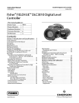
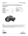
Field Communicator Menu Tree
Hot Key
FIELDVUE™ DLC3010 Digital Level Controller
1 Write Lock
2 Write Lock Setup
3 Change PV
4 Enter Contstant Density
www.Fisher.com
1 Device Status
2 Comm Status
3 PV is
4 Primary Variable
5 AO
6 Process Temperature
7 Device Information
Online
For the telephone number of the Emerson Process
Management sales office nearest you, contact:
1 Overview
2 Configure
3 Service Tools
In North America
Fisher Controls International LLC
1 (641) 754‐3011
In Latin America
Fisher Controls International LLC
1 (314) 746‐9900
Overview
2‐1
Guided Setup
3
1 Active Alerts
2 Variables
3 Maintenance
DLC3010 Digital Level Controller
In Asia Pacific
Emerson Process Management
Asia Pacific Private Ltd.
(65) 6777‐8211
In Europe
Emerson Process Management Ltd.
+44 1634 895800
For equipment service or support needs, contact
your local Emerson Process Management sales office
1 LCD Test 1
2 Loop Test
1 Restore Factory
Defaults
2 Reset Device
www.Fisher.com
D102732X012 October 2012
FIELDVUE and Fisher are marks owned by one of the companies in the Emerson Process
Management business unit of Emerson Electric Co. Emerson, Emerson Process
Management, and the Emerson logo are trademarks and service marks of Emerson
Electric Co.
1 Restore Factory
Configuration
2 Restore Factory
Compensation
1‐6
Process Temperature
1 Proc Temp Source
2 Proc Temp
1-7
Device Information
3-1
Active Alerts 2
1 No Active Alerts
1 Refresh Alerts
3-2
Variables
2‐5-2
Secondary
1 Temperature Calibration
1 PV
2 Analog Output Calibration
2 Primary Variable
3 AO
2‐5-2-2
4 Inst Temp
Analog Output Calibration
5 Process Temperature
1 Scaled D/A/ Trim
6 Torque Rate
7 Upper Fluid Density 3
2‐5-2-1
8 Lower Fluid Density 4
Temperature Calibration
1
LCD Test is visible if LCD Configuration is installed.
2
3
No Active Alerts visible if there are no active alerts.
Refresh Alerts visible if an alert is active.
Upper Fluid Density visible if PV is Interface.
4
Lower Fluid Density visible if PV is Interface or Level.
1 Trim Instrument Temperature
2 Trim Processs Temperature
2 (Visible if Process Temperature
2 is not Manual)
Device Revision
1 HART Universal Revision
2 Field Device Revision
3 Firmware Revision
4 Hardware Revision
5 DD Information
1 Burst Mode
2 Burst Options
1 Sensor
2 Variables
3 Process Fluid
4 Identification
5 Instrument Display
2‐2‐5
Instrument Display
2‐5-1-3
Partial Calibration
1 Capture Zero
2 Trim Gain
3 Trim Zero
2‐5-1-2
Full Calibration
1 Min/Max Calibration
2 Two Point Calibration
3 Weight Calibration
1 LCD Configuration
2 Display Mode
3 Change Display Mode
4 Decimal Places
2‐2‐4
Identification
1
1
1 Alarm Jumper
2 Display Alert/Saturation Level
1‐7-3-2
Security
1 Write Lock
2 Write Lock Setup
1 HART Tag
1 Proc Temp Source
2 Date
2 Change Proc Temp
3 Descriptor
3 Proc Temp
4 Message
4 RTD Wire Resistance
5 Polling Address
6 Physical Signaling Code
7 Number of Request Preambles
8 Serial Numbers
DD Revision
8
3
1 Length Units
2 Volume Units
3 Weight Units
4 Torque Rate Units
5 Temperature Units
2‐2-1
Sensor
1 Sensor Units
2 Sensor Dimensions
3 Torque Tube
4 Instrument Mounting
5 Sensor Damping
2‐2‐1-3
Torque Tube
2‐2-3
Process Fluid (if PV is Density)
Firmware Revision
2‐2‐1-1
Sensor Units
2‐2
Manual Setup
2‐4
Communications
Hardware Revision
1‐7-3-1
Alarm Types
1 Alarm Type
2 Security
2‐5-1
Primary
1 Guided Calibration
2 Full Calibration
3 Partial Calibration
Menu Tree applies to
1‐7-2
Revisions
1‐7-3
Alarm Type and Security
1 Identification
2 Revisions
3 Alarm Type and
Security
2‐5
1 Primary
2 Secondary
3-3-2
Reset/Restore
3-3-2-1
Restore Factory Defaults
© 2005, 2012 Fisher Controls International LLC. All rights reserved.
Calibration
Tests
475 Field
Communicator
1 PV Value
2 % Range
1 Guided Setup
2 Manual Setup
3 Alert Setup (See Reverse Side)
4 Communications
5 Calibration
3-3-1
1 HART Tag
2 Distributor
3 Model
4 Device ID
5 Instrument Serial Number
6 Sensor Serial Number
7 Final Assembly Number
8 Date
9 Descriptor
9 Message
Primary Variable
Configure
1 Tests
2 Reset/Restore
Identification
1‐4
2
3-3
Maintenance
1‐7-1
1 Refresh Alerts
2 No Active Alerts
1 Instrument Setup
Service Tools
Device Status
If PV is Level or Interface
1
If PV is Density
1‐1
1 Torque Rate
2 Change Torque Rate
3 TT Material
4 TT Comp Selection
5 TT Comp Table
2‐2‐2
Variables
1 Primary Variables
2 Sensor Limits
3 Primary Variable Range
4 PV Damping
2‐2-3
Process Fluid
(if PV is Level or Interface)
1 Process Fluid
2 Process Temperature
2‐2‐4-8
Serial Numbers
1 Instrument Serial Number
2 Sensor Serial Number
3 Final Assembly Number
2‐2‐1-2
Sensor Dimensions
1 Displacer Length
2 Displacer Volume
3 Displacer Weight
4 Driver Rod Length
2‐2‐2-1
Primary Variables
1 PV is
2 Change PV
3 PV Units
4 Level Offset
5 Set Level Offset
2‐2‐2-2
Sensor Limits
1 Upper Sensor Limit
2 Lower Sensor Limit
3 Minimum Span
2‐2‐2-3
Primary Variable Range
1 Upper Range Value
2 Lower Range Value
3 View/Change AO Action
2‐3
Alert Setup
Function/Variable
Alert Setup
2 Configure
Active Alerts
Alarm Jumper
1 Primary Variable
2 Temperature
1 Guided Setup
2 Manual Setup
3 Alert Setup
4 Communications
5 Calibration
2‐3-1
Analog Output
Primary Variable
1 Primary Variable Hi
2 Primary Variable Lo
3 Upper Range Value
4 Lower Range Value
5 PV Alerts Threshold
5 Deadband
2‐3-2
Temperature
1 Instrument Temperature
2 Process Temperature
2‐3-2-2
Process Temperature
2‐3-1-2
Primary Variable Lo
1 Hi Alert
2 Lo Alert
3 Proc Temp
4 Proc Temp Offset
2‐3-1-1
1 Lo Alert
2 LoLo Alert
Primary Variable Hi
1 Hi Alert
2 HiHi Alert
2‐3-2-2-2
Change Process Temperature
Lo Alert
1 Proc Temp Lo Alert Enable
2 Proc Temp Lo Alert Threshold
2‐3-2-2-1
Hi Alert
1 Proc Temp Hi Alert Enable
2 Proc Temp Hi Alert Threshold
2‐3-2-1
Instrument Temperature
1 Hi Alert
2 Lo Alert
3 Inst Temp
4 Inst Temp Offset
2‐3-2-1-2
Lo Alert
1 Inst Temp Lo Alert Enable
2 Inst Temp Lo Alert Threshold
2‐3-2-1-1
2‐3-1-1-2
HiHi Alert
1 PV HiHi Alert Enable
2 PV HiHi Alert Threshold
3 PV HiHi Alert Threshold
2‐3-1-1-1
Hi Alert
1 PV Hi Alert Enable
2 PV Hi Alert Threshold
3 PV Hi Alert Threshold
2‐3-1-2-1
Lo Alert
1 PV Lo Alert Enable
2 PV Lo Alert Threshold
3 PV Lo Alert Threshold
2‐3-1-2-2
Hi Alert
LoLo Alert
1 Inst Temp Hi Alert Enable
2 Inst Temp Hi Alert Threshold
1 PV LoLo Alert Enable
2 PV LoLo Alert Threshold
3 PV LoLo Alert Threshold
Italics text indicates Method
Burst Mode
Burst Options
Calibration, Guided
Calibration, Min/Max
Calibration, Partial, Capture Zero
Calibration, Partial, Trim Gain
Calibration, Partial, Trim Zero
Calibration, Temperature
Calibration, Two Point
Calibration, Weight
Change Primary Variable
Change Torque Rate
Comm Status
Date
DD Information
Decimal Places
Descriptor
Device ID
Device Status
Display Alert/Saturation Level
Display Mode
Distributor
Enter Constant Density
Field Device Revision
Final Assembly Number
Firmware Revision
Guided Setup
Hardware Revision
Fast‐Key Sequence
3-1
1-7-3-1-1
1-5
3-2-3
2-4-1
2-4-2
2-5-1-1
2-5-1-2-1
2-5-1-3-1
2-5-1-3-2
2-5-1-3-3
2-5-2-1
2-5-1-2-2
2-5-1-2-3
2-2-3-2(1)
2-2-3-2-2(2)(3)
Hot Key-3
2-2-2-1-2
2-2-1-3-2
1-2
1-7-1-8
2-2-4-2
1-7-2-5
2-2-5-4
1-7-1-9
2-2-4-3
1-7-1-4
1-1
1-7-3-1-2
2-2-5-2
1-7-1-2
Hot-Key-4
2-2-3-1-3(2)(5)
2-2-3-1-4(2)(6)
1-7-2-2
1-7-1-7
2-2-4-8-3
1-7-2-3
2-1
1-7-2-4
Function/Variable
HART Tag
HART Universal Revision
Instrument Mounting
Instrument Serial Number
Instrument Temperature
Instrument Temperature (Alert Setup)
LCD Configuration
LCD Test
Level Offset
Loop Test
Lower Density Table(3)
Lower Fluid Density
Lower Range Value
Lower Sensor Limit
Measure Density
Message
Minimum Sensor Span
Model (Device)
Number of Request Preambles
Percent Range
Physical Signalling Code
Polling Address
Primary Variable Hi (Alert Setup)
Primary Variable Lo (Alert Setup)
Process Temperature
Process Temperature (Alert Setup)
Process Temperature Source
Fast‐Key Sequence
1-7-1-1
2-2-4-1
1-7-2-1
2-2-1-4
1-7-1-5
2-2-4-8-1
3-2-4
2-3-2-1
2-2-5-1
3-3-1-1(4)
2-2-2-1-4
3-3-1-1
3-3-1-2(4)
2-2-3-1-2-1(3)(5)
2-2-3-1-3-2(3)(6)
2-2-3-1-1(3)(5)
2-2-3-1-2(3)(6)
3-2-7(5)
3-2-8(6)
2-2-2-3-2
2-3-1-4
2-2-2-2-2
2-2-3-1-4(3)(5)
2-2-4-4
2-2-2-2-3
1-7-1-3
2-2-4-7
1-4-2
3-2-2-2(3)
2-2-4-6
2-2-4-5
2-3-1-1
2-3-1-2
1-6-2
2-2-3-2-3(2)(3)
2-2-3-3(1)
3-2-5-2(3)
2-3-2-2
1-6-1
2-2-3-1(1)
Function/Variable
Process Temperature Source
PV Alerts Threshold Deadband
PV Damping
PV is
PV Units
PV Value
Reset Device
Restore Factory Defaults
RTD Wire Resistance
Scaled D/A Trim
Sensor Damping
Sensor Dimensions (Displacer Units)
Sensor Serial Number
Sensor Units
Set Level Offset
Torque Rate
Torque Tube Compensation Selection
Torque Tube Compensation Table
Torque Tube Material
Upper Density Table
Upper Fluid Density
Upper Range Value
Upper Sensor Limit
View/Change AO Action
Write Lock
Write Lock Setup
1. If PV is Density
2. If PV is Level or Interface
3. Not included in menu tree
4. LCD Configuration is installed
5. If PV is Level
6. If PV is Interface
Fast‐Key Sequence
2-2-3-2-1(2)(3)
2-3-1-5
2-2-2-4
1-3
2-2-2-1-1
2-2-2-1-3
1-4-1
3-2-2-1(3)
3-3-2-2
3-3-2-1
2-2-3-2-4(2)(3)
2-2-3-4(1)
2-5-2-2-1
2-2-1-5
2-2-1-2
1-7-1-6
2-2-4-8-2
2-2-1-1
2-2-2-1-5
2-2-1-3-1
3-2-6
2-2-1-3-4
2-2-1-3-5
2-2-1-3-3
2-2-3-1-3-1(3)(6)
2-2-3-1-1(3)(6)
3-2-7(6)
2-2-2-3-1
2-3-1-3
2-2-2-2-1
2-2-2-3-3
Hot Key-1
1-7-3-2-1
Hot Key-2
1-7-3-2-2