1
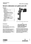
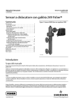
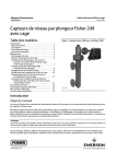
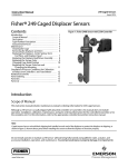
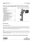
Instruction Manual
249 Cageless Sensors
D200100X012
December 2012
Fisherr 249 Cageless Displacer Sensors
Contents
Introduction . . . . . . . . . . . . . . . . . . . . . . . . . . . . . . . . . 1
Scope of Manual . . . . . . . . . . . . . . . . . . . . . . . . . . . . . 1
Description . . . . . . . . . . . . . . . . . . . . . . . . . . . . . . . . . 1
Type Number Description . . . . . . . . . . . . . . . . . . . . . 2
Educational Services . . . . . . . . . . . . . . . . . . . . . . . . . 3
Maintenance . . . . . . . . . . . . . . . . . . . . . . . . . . . . . . . . . 3
Removing the Displacer and Stem . . . . . . . . . . . . . . 4
Replacing the Displacer, Cotter Spring,
Stem End Piece, and Displacer Spud . . . . . . . . . . 6
Replacing the Displacer Rod/Driver Assembly . . . . 7
Replacing the Torque Tube . . . . . . . . . . . . . . . . . . . . 8
Replacing the Torque Tube Arm and
Changing the Mounting . . . . . . . . . . . . . . . . . . . . 9
Simulation of Process Conditions for
Calibration of Fisher Level Controllers
and Transmitters . . . . . . . . . . . . . . . . . . . . . . . . . . . . 10
Parts Ordering . . . . . . . . . . . . . . . . . . . . . . . . . . . . . . . 10
Parts Kits . . . . . . . . . . . . . . . . . . . . . . . . . . . . . . . . . . . 11
Parts List . . . . . . . . . . . . . . . . . . . . . . . . . . . . . . . . . . . 11
Sensor Common Parts . . . . . . . . . . . . . . . . . . . . . . . 11
Figure 1. Fisher 249V Sensor with FIELDVUE™
DLC3010/DLC3020f Digital Level Controller
W3120‐3
Introduction
Scope of Manual
This instruction manual includes maintenance and parts ordering information for Fisher 249 cageless displacer
sensors.
Although a 249 sensor is usually shipped with attached controller or transmitter, this manual does not include
operation, installation, calibration, maintenance, and parts ordering information for the controller/transmitter or for
the complete unit. For this information, refer to the appropriate controller/ transmitter instruction manual.
Do not install, operate, or maintain a 249 sensor without being fully trained and qualified in valve, actuator, and
accessory installation, operation, and maintenance. To avoid personal injury or property damage, it is important to
carefully read, understand, and follow all of the contents of this manual, including all safety cautions and warnings. If
you have any questions about these instructions, contact your Emerson Process Management sales office.
Description
249 sensors are designed to measure liquid level, interface level, or density/specific gravity inside a process vessel.
www.Fisher.com
Instruction Manual
249 Cageless Sensors
D200100X012
December 2012
A torque tube assembly (figure 2) and displacer provide an indication of liquid level, interface level, or density/specific
gravity. The torque tube assembly consists of a hollow torque tube with a shaft welded inside it at one end and
protruding from it at the other end.
Figure 2. Typical Side‐Mounted Cageless Displacer
TRAVEL STOP ASSEMBLY
W1800‐1
KNIFE EDGE BEARING
DISPLACER ROD
DISPLACER
TORQUE TUBE
W0172‐1
The unconnected end of the tube is sealed by a gasket and clamped rigidly to the torque tube arm, permitting the
protruding end of the shaft to twist and therefore transmit rotary motion. This allows the interior of the torque tube to
remain at atmospheric pressure, thus eliminating packing and the disadvantages of packing friction.
The displacer always exerts a downward force on one end of the displacer rod. The other end of the displacer rod rests
on the knife‐edge of the driver bearing. A keyed shaft on the bearing end of the displacer fits into a socket on the
outside of the welded end of the of the torque tube assembly.
A change in liquid level, interface level, or density/specific gravity buoys up the displacer by a force equal to the weight
of the liquid displaced. Corresponding vertical movement of the displacer results in angular movement of the displacer
rod around the knife edge. Since the torque tube assembly is a torsional spring which supports the displacer and
determines the amount of movement of the displacer rod for a given displacement change, it will twist a specific
amount for each increment of buoyancy change. This rotation is brought through the torque tube arm by the
protruding rotary shaft. A controller or transmitter attached to the end of the rotary shaft converts the rotary motion
into varying pneumatic or electric signals.
Unless otherwise noted, all NACE references are to NACE MR0175-2002.
Type Number Description
D 249BP—CL150, 300, 600 steel top‐mounted sensor
D 249CP—CL150, 300, 600 stainless steel top‐mounted sensor
2
Instruction Manual
249 Cageless Sensors
D200100X012
December 2012
D 249P—CL150, 300, 600, 900 or 1500 steel top‐mounted sensor
Note
249P CL150, 300, and 600 sensors are only available in Europe.
D 249V—CL125 or 250 cast iron or CL150, 300, 600, 900, or 1500 steel side‐mounted sensor
Note
249V sensors are only available in Europe.
All cageless 249 sensors have flanged connections.
The Parts List section shows some 249 sizes by construction, standard displacer lengths, and standard materials and
table 1 contains displacer and torque tube materials. However, 249 parts are available in a wide variety of materials of
construction, part dimensions, and other specifications. Contact your Emerson Process Management sales office for
assistance in selection of specific materials, dimensions, and specifications.
Table 1. Displacer and Torque Tube Materials
Standard Material
Other Materials
Displacer
Part
304 Stainless Steel
316 Stainless Steel, N10276, N04400, Plastic, and Special Alloys
Displacer Stem, Driver Bearing,
Displacer Rod and Driver
316 Stainless Steel
N10276, N04400, other Austenitic Stainless Steels, and Special Alloys
N05500(1)
316 Stainless Steel, N06600, N10276
Torque Tube
1. N05500 is not recommended for spring applications above 232_C (450_F). Contact your Emerson Process Management sales office or application engineer if temperatures exceeding this
limit are required.
Educational Services
For information on available courses for 249 displacer sensors, as well as a variety of other products, contact:
Emerson Process Management
Educational Services, Registration
P.O. Box 190; 301 S. 1st Ave.
Marshalltown, IA 50158-2823
Phone: 800-338-8158 or
Phone: 641-754-3771
FAX: 641-754-3431
e‐mail: [email protected]
Maintenance
Sensor parts are subject to normal wear and must be inspected regularly and replaced as necessary. The frequency of
inspection and replacement depends upon the severity of service conditions.
3
249 Cageless Sensors
December 2012
Instruction Manual
D200100X012
WARNING
Always wear protective clothing, gloves, and eyewear when performing any maintenance operations to avoid personal
injury.
Avoid personal injury or property damage resulting from the sudden release of pressure. Before performing any
maintenance procedure:
D Relieve any process pressure in the process vessel where the 249 sensor is installed.
D Drain the process liquid from the process vessel.
D Shut off any electrical or pneumatic input to the controller or transmitter attached to the 249 sensor and vent any
pneumatic supply pressure.
D Use caution when loosening flange bolting or pipe plugs (key 26).
D Remove the controller or transmitter from the torque tube arm (key 3).
Before performing any maintenance procedure requiring the handling of the displacer, inspect the displacer (key 10) to
make sure process pressure or liquids have not penetrated the displacer.
The displacer in this unit is a sealed container. If penetrated by process pressure or liquid, the displacer may hold pressure
or hazardous liquid for an extended period. A displacer that has been penetrated by process pressure or liquid may contain:
D pressure as a result of being in a pressurized vessel.
D liquid that becomes pressurized due to a change in temperature.
D liquid that is flammable, hazardous, or corrosive.
Sudden release of pressure, contact with hazardous liquid, fire, or explosion, which might result in personal injury or
property damage, can occur if a displacer that is retaining pressure or process liquid is punctured, subjected to heat, or
repaired.
Handle the displacer with care. Consider the characteristics of the specific process liquid in use.
Check with your process or safety engineer for any additional measures that must be taken to protect against process
media.
Note
Except for gaskets (keys 13, 14), trouble symptoms peculiar to specific parts are discussed in the following sections. Each section is
specific to these parts. Regardless of location, gasket failure is indicated by leakage in the gasket area. Every time a gasket is
removed, replace it with a new one upon reassembly.
The procedures below apply to all sensor types except where indicated. Key numbers used are shown in the following
illustrations:
D 249BP—figure 5
D 249CP—figure 6
D 249P—figure 7
D 249V—figure 8
Removing the Displacer and Stem
The displacer (key 10) is a sealed container. If the displacer has been penetrated by process pressure or liquid, it may
hold pressure or hazardous liquid for an extended period.
4
Instruction Manual
249 Cageless Sensors
D200100X012
December 2012
Process residue buildup on the displacer and stem (key 24) may change displacer weight or displacement. A bent stem
or a dented or corroded displacer can impair performance.
If the displacer rests against the travel stop, appears to be overweight, or causes output drift or other output
inaccuracies, it may have been penetrated by process pressure or liquid. Such a displacer may contain pressure
because it was in a pressurized vessel, may contain process liquid that becomes pressurized due to a change in
temperature, and may contain process liquid that is flammable, hazardous, or corrosive.
WARNING
Sudden release of pressure, contact with hazardous liquid, fire, or explosion, which may result in personal injury or
property damage, can occur if a displacer that is retaining pressure or process liquid is punctured, subjected to heat, or
repaired.
Handle the displacer with care.
Note
On the 249V, 249P, and 249BP with travel stop, the displacer must come out with the sensor head (key 2) or torque tube arm
(key 3) before being completely disconnected from the displacer rod (key 7). If separating the displacer and displacer rod, remove
the cotter spring (key 11).
CAUTION
Be careful not to let the displacer slip and drop into the bottom of the process vessel, as displacer damage could result.
1. Before starting any maintenance procedure, be sure the following safety actions are completed.
D Relieve process pressure in the process vessel where the 249 sensor is installed.
D Drain the process liquid from the process vessel.
D Shut off any electrical or pneumatic input to the controller or transmitter attached to the 249 sensor and vent
any pneumatic supply pressure. Remove the controller or transmitter from the torque tube arm.
D Use caution when loosening flange bolting or pipe plugs.
D Be sure process pressure or liquids have not penetrated the displacer.
2. Support the sensor head (key 2) and the torque tube arm (key 3). Remove the bolting that holds the sensor head to
the process vessel.
CAUTION
When removing a sensor from a process vessel, the displacer may remain attached to the displacer rod and be lifted out
with the sensor head (key 2) when the sensor head is removed. If separating the displacer and displacer rod before
removing the sensor head, remove the cotter spring (key 11). If the displacer comes out with the head or torque tube arm,
be careful not to damage the displacer or bend the stem when setting the head or arm down.
5
Instruction Manual
249 Cageless Sensors
D200100X012
December 2012
Be careful not to let the displacer slip and drop into the bottom of the process vessel, as displacer damage could result.
3. Carefully remove the sensor head or torque tube arm.
4. On the 249V, the travel stop plate can be located in one of four positions as shown in figure 3.
For proper operation in the target application, the displacer rod must not touch either plate over the expected
range of process conditions.
D When the displacer is completely submerged in the upper fluid, the net load of weight minus buoyancy must be
low enough to allow the displacer rod to be above the lower plate.
D When the displacer is completely submerged in the lower fluid, the net load of weight minus buoyance must be
high enough to keep the displacer rod from hitting the upper plate.
If necessary, remove the place and choose a position where the rod will not touch the plate.
Figure 3. Fisher 249V Travel Stop Plate Positions
1
HIGH
2
INTERMEDIATE
3
INTERMEDIATE
4
LOW
BJ8646‐A
5. Follow the procedure for replacing the displacer, displacer rod assembly, cotter spring, stem end piece, and
displacer spud as necessary.
Replacing the Displacer, Cotter Spring, Stem End Piece, and Displacer
Spud
The cotter spring (key 11), the ball on the displacer rod/driver assembly (key 7), and the stem end piece or displacer
stem connector (key 23) may be either too worn for a secure connection or so clogged or corroded that the displacer
does not pivot properly. Replace these parts, as necessary.
CAUTION
If the displacer is to be disconnected from the displacer rod before being removed from the process vessel, provide a
suitable means of supporting the displacer to prevent it from dropping into the process vessel and being damaged.
6
Instruction Manual
D200100X012
249 Cageless Sensors
December 2012
1. After following the proper procedure to remove the sensor head and the displacer from the process vessel, move
the sensor assembly to a suitable maintenance area. Support the assembly to avoid damage to the displacer,
displacer stem, displacer rod/driver assembly, and associated parts.
2. To help support the displacer on a unit without travel stop (249BP, 249P, 249CP), install the stem and stem end
piece (or a threaded rod) into the 1/4 inch‐28 UNF threaded hole in the displacer spud or stem connector. On the
249BP with travel stop, the groove pin (key 42) will secure the displacer as long as the travel stop plate (key 41) is
installed and the sensor head (key 2) is in position.
3. Reach the cotter spring, displacer spud, ball end of the displacer rod/driver assembly, stem end piece, or displacer
stem connector as follows:
D Top‐Mounted 249BP, 249CP, and 249P Sensors—By removing the pipe plug (key 26).
D Side‐Mounted 249V Sensor—By removing the process vessel bolting and pulling out the torque tube arm (key 3).
The inside of the process vessel wall will cause the displacer to swing up so it can be pulled out through the vessel
opening.
4. Remove the cotter spring to free the displacer or stem end piece from the ball end of the displacer rod/driver
assembly. Lift the displacer or stem end piece from the ball.
5. Replace worn or damaged parts as necessary. Return the displacer or stem end piece to the displacer rod/driver
assembly. Install the cotter spring.
6. Install the sensor head and controller/transmitter. Calibrate the controller/transmitter following the procedures
given in the controller/transmitter instruction manual.
Replacing the Displacer Rod/Driver Assembly
The ball on the displacer rod/driver assembly (key 7) may be either too worn for a secure connection or so corroded
that the displacer does not pivot properly. Replace the displacer rod/driver assembly, if necessary.
CAUTION
If the displacer is to be disconnected from the displacer rod/driver assembly before being removed from the process vessel,
provide a suitable means of supporting the displacer to prevent it from dropping into the process vessel and being
damaged.
1. After following the proper procedure to remove the sensor head and the displacer from the process vessel, move
the sensor assembly to a suitable maintenance area. Support the assembly to avoid damage to the displacer,
displacer stem, displacer rod assembly, and associated parts.
2. Remove the controller/transmitter and displacer (key 10). Then, remove the hex nuts (key 20) that hold the torque
tube arm (key 3) to the sensor head (key 2). Separate the torque tube arm from the sensor head.
3. Remove the nuts (key 18) and retaining flange (key 6) at the end of the torque tube arm.
4. Remove the positioning plate (key 8) by freeing its two lugs.
The vertical lug fits into a hole in the flange of the torque tube arm (top of figure 4, left). The horizontal lug (hidden
behind the screwdriver at the bottom of figure 4, left) fits into a slot in the outer tube end of the torque tube
assembly (figure 4 exploded view shows this lug to the right of the outer tube end).
Place a screwdriver blade in the slots of the positioning plate and outer tube ends as shown in figure 4. Slowly turn
the positioning plate to release its lug from the torque tube arm. Then carefully turn the plate back to allow the
displacer to come to rest, and slip the other lug of the plate from its slot in the outer tube end.
5. Pull the torque tube assembly out of the torque tube arm. Remove the tube end gasket (key 14) and discard (a new
gasket will be installed in step 9). Clean and inspect the gasket mating surfaces.
7
Instruction Manual
249 Cageless Sensors
D200100X012
December 2012
Figure 4. Torque Tube and Displacer Rod Assemblies
DISPLACER ROD
ASSEMBLY
GASKET
ROTARY
SHAFT
TORQUE TUBE
OUTER TUBE END
POSITIONING PLATE
W0145‐2
W0654‐1
DRIVER BEARING
EXPLODED VIEW OF TORQUE TUBE AND DISPLACER ROD ASSEMBLY
REMOVAL OR INSTALLATION OF POSITIONING PLATE
6. Using the proper tool, loosen and then remove the upper bearing driver bolt (key 5). Lift the displacer rod/driver
assembly from the knife edge of the driver bearing (key 4).
7. Visually inspect the bearing driver for corrosion or wear. If replacement is necessary, remove the bearing driver by
removing the lower bearing driver bolt. Install a new bearing driver and the lower bearing driver bolt.
8. Install the new displacer rod/driver assembly on the knife edge of the bearing driver. Install the upper bearing driver
bolt (key 5), but do not tighten.
9. Insert new tube end gasket into recess in torque tube arm.
10. Insert the torque tube assembly and rotate until its socket mates with the displacer rod assembly and so that the
outer tube flange rests against the gasket.
11. With a thumb on the upper portion of the positioning plate and a screwdriver in the slots as shown in figure 4,
rotate the plate and press the lug on the plate into the hole in the torque tube arm (this will preload the torque
tube).
12. Install the retaining flange and secure it with four nuts (key 18), being sure to tighten all nuts evenly.
13. Tighten the upper bearing driver bolt (key 5). It will be necessary to put slight pressure on the displacer rod/driver
assembly to access the upper bearing driver bolt.
14. Install the sensor head and controller/transmitter. Calibrate the controller/transmitter following the procedures
given in the controller/transmitter instruction manual.
Replacing the Torque Tube
Corrosion or leakage through the outer end of the torque tube is evidence of deterioration in the torque tube
assembly (key 9) or torque tube end gasket (key 14). Erratic or nonexistent rotary shaft output may occur if the socket
on the inner end of the torque tube assembly does not engage the bearing end of the displacer rod assembly (key 7).
1. After following the proper procedure to remove the sensor head and the displacer from the process vessel, move
the sensor assembly to a suitable maintenance area.
CAUTION
Support the sensor assembly to avoid damage to the displacer, displacer stem, displacer rod assembly, and associated
parts.
8
Instruction Manual
249 Cageless Sensors
D200100X012
December 2012
2. Remove the controller/transmitter and displacer (key 10). Then, remove the hex nuts (key 20) that hold the torque
tube arm (key 3) to the sensor head (key 2). Separate the torque tube arm from the sensor head.
3. Remove the nuts (key 18) and retaining flange (key 6) holding the positioning plate (key 8) at the end of the torque
tube arm.
CAUTION
If the displacer is still attached to the displacer rod at this point, be careful not to let the torque tube assembly slip when
using the screwdriver leverage procedure in steps 4 and 6. Sudden release of the displacer could cause damage.
4. Remove the positioning plate (key 8) by freeing its two lugs.
The vertical lug fits into a hole in the flange of the torque tube arm (top of figure 4). The horizontal lug (hidden
behind the screwdriver at the bottom of figure 4) fits into a slot in the outer tube end of the torque tube assembly
(the figure 4 exploded view shows this lug to the right of the outer tube end).
The positioning plate may be pried away from the torque tube arm and outer tube end if the displacer already has
been disconnected from the displacer rod. However, if the displacer is still connected to the displacer rod, place a
screwdriver blade in the slots of the positioning plate and outer tube end as shown in figure 4. Slowly turn the
positioning plate to release its lug from the torque tube arm. Then, carefully turn the plate back to allow the
displacer to come to rest and slip the other lug of the plate from its slot in the outer tube end.
5. Pull the torque tube assembly and tube end gasket out of the torque tube arm. Remove the tube end gasket
(key 14) and discard (a new gasket will be installed in step 6). Clean and inspect the gasket mating surfaces.
6. Insert new tube end gasket into recess in torque tube arm.
7. Insert the torque tube assembly into the torque tube arm as shown in figure 4. Rotate the torque tube assembly
until its socket mates with the driver member on the displacer rod assembly and so the outer tube flange rests
against the gasket. With a thumb on the upper portion of the positioning plate and a screwdriver in the slots as
shown in figure 4, rotate the plate and press the lug on the plate into the hole in the torque tube arm (this will
preload the torque tube).
8. Install the retaining flange and secure it with four nuts (key 18), being sure to tighten all nuts evenly.
9. Install the sensor head and controller/transmitter. Calibrate the controller/transmitter following the procedures
given in the controller/transmitter instruction manual.
Replacing the Torque Tube Arm and Changing the Mounting
Looseness of the driver bearing (key 4), wear on its knife‐edged surface, or a bent, worn, or corroded displacer rod
assembly (key 7) may impair performance. Be especially sure to check the ball on the displacer rod.
1. After following the proper procedure to remove the sensor head and the displacer from the process vessel, move
the sensor assembly to a suitable maintenance area.
CAUTION
Support the sensor assembly to avoid damage to the displacer, displacer stem, displacer rod assembly, and associated
parts.
2. Remove the controller/transmitter and displacer (key 10). Then, remove the hex nuts (key 20) that hold the torque
tube arm (key 3) to the sensor head (key 2). Separate the torque tube arm from the sensor head.
9
249 Cageless Sensors
December 2012
Instruction Manual
D200100X012
3. Follow the proper procedure to remove the torque tube assembly (key 9).
4. Remove the bearing bolts (key 5), displacer rod assembly, and driver bearing.
Note
Be sure to install the driver bearing so its knife edge is pointing up when the torque tube arm is mounted in the desired orientation.
Since changing the mounting position of the torque tube arm by 180_ will change controller or transmitter action from direct to
reverse or vice versa, controller/transmitter action must be reversed from what it was before the mounting method was changed.
5. Install the driver bearing, displacer rod assembly, and bearing bolts (key 5) into the torque tube arm. Install a new
arm gasket. Install the torque tube arm on the sensor head or process vessel and secure it with the proper bolting
(keys 19 and 20).
6. Install the torque tube assembly. Install the displacer.
7. Install the sensor head and controller/transmitter. Calibrate the controller/transmitter following the procedures
given in the controller/transmitter instruction manual.
Simulation of Process Conditions for Calibration of Fisher Level
Controllers and Transmitters
Contact your Emerson Process Management sales office for information on obtaining the Supplement to 249 Sensor
Instruction Manuals—Simulation of Process Conditions for Calibration of Fisher Level Controllers and Transmitters
(D103066X012), or visit our website at www.Fisher.com.
Parts Ordering
When corresponding with your Emerson Process Management sales office about this equipment, always refer to the
sensor serial number. Each sensor is assigned a serial number which is stamped on a nameplate (key 54, not shown)
attached to the torque tube arm. This same number also appears on the controller/ transmitter nameplate when a
complete controller/ transmitter‐sensor unit is shipped from the factory. When ordering a replacement part, be sure
to include the 11‐character part number from the following parts list.
WARNING
Use only genuine Fisher replacement parts. Components that are not supplied by Emerson Process Management should
not, under any circumstances, be used in any Fisher instrument. Use of components not supplied by Emerson Process
Management may void your warranty, might adversely affect the performance of the instrument, and could cause personal
injury or property damage.
10
Instruction Manual
249 Cageless Sensors
D200100X012
December 2012
Parts Kits
Description
Sensor Part Kit
Kit contains keys 9, 11, 13, 14
For 249BP
Key
Description
9*
Torque Tube Assy(1)
For 249BP
N05500
Std wall
Heavy wall
Thin wall
For 249CP
S31600
Std wall
Heavy wall
For 249P
N05500
Std wall
Thin wall
For 249V
N05500
Std wall
Thin wall
Part Number
R249X000012
10
Parts List
Part numbers are shown for recommended spares only. For part
numbers not shown, contact your Emerson Process Management sales
office.
Key
Description
2
Sensor Head
For 249BP, 249CP, 249P
(If a part number is required, contact your Emerson Process
Management sales office.) Not req'd for 249V
Torque Tube Arm
For 249V
(If a part number is required, contact
your Emerson Process Management sales office.)
3
4
5
6
7
8
Driver Bearing, S31600
Driver Bearing Bolt, S31600 (2 req'd)
Retaining Flange
(If a part number is required, contact
your Emerson Process Management sales office.)
Rod/Driver Assy, S31600
Positioning Plate, S31600
1K4493X0012
1K4497X0012
1K4495X0012
1K4505000A2
1K4503000A2
1K4499X0012
1K4501X0012
1K4499X0012
1K4501X0012
Displacer(1)
For 249BP, 249CP
3 inch X 14 inches (1600 psi), S30400 or S31600
2 inch x 32 inches (1500 psi), S30400 or S31600
1.5 inch x 60 inches (1800 psi), S30400
1.375 inch x 72 inches (1400 psi), S30400
For 249P
2.75 inch x 14 inches (6000 psi), S30400 or S31600
2.875 inch x 14 inches (4000 psi), S30400
1.75 inch x 32 inches (4200 psi), S30400 or S31600
1.9062 inch x 32 inches (3400 psi), S30400 or S31600
For 249V
3 inch x 10 inches (1600 psi), S30400 or S31603 (NACE)
3 inch x 14 inches (1600 psi), S31600 or S31603 (NACE)
2 inch x 32 inches (1500 psi), S30400 or S31600
2 inch x 32 inches (1500 psi), S31603 (NACE)
1.375 inch x 48 inches (1800 psi), S30400
1.5 inch x 60 inches (1800 psi), S30400
Note
Sensor Common Parts
Part Number
11*
13*
14*
15
16
18
Cotter Spring(1), N04400 (2 req'd)
Arm Gasket(1)
For 249BP, 249CP
thru CL600, graphite/SST
For 249P
CL900 & 1500 graphite/SST
Tube End Gasket(1)
For 249BP, 249CP, or 249V
thru CL600, graphite/SST
For 249P
CL900 & 1500 graphite/SST
Stud Bolt(1), steel B7 (4 req'd)
For 249BP, 249CP, 249V
(249V thru CL600)
For 249P
CL900 & 1500
1A517942022
1E5629X0072
1A1297X0022
0Y0876X0052
0Y0876X0052
Groove Pin, S31600
For 249BP, 249CP, 249P
Hex Nut(1), steel B7 (4 req'd)
For 249BP, 249CP, and 249V
thru CL600
For 249P
CL900 & 1500
*Recommended spare parts
1. This part is available in a wide variety of materials of construction, part dimensions, or other
specifications. Listed here are standard or typical materials, dimensions, or specifications.
Contact your Emerson Process Management sales office for assistance in selection of specific
materials, dimensions, or specifications.
11
Instruction Manual
249 Cageless Sensors
D200100X012
December 2012
Figure 5. Fisher 249BP Sensor Construction
SECTION A‐A
DETAIL OF TRAVEL STOP VERSION
20A7432‐B
20A7433‐B
Key
Description
19
Bolt Stud(1), steel B7 (4 req'd)
20
For 249B, 249CP
thru CL600
For 249P
CL900 & 1500
Hex Nut(1), steel (8 req'd)
For 249BP, 249CP
thru CL600
For 249P
CL900 & 1500
23
12
Displacer Stem End Piece(1), S31600
For 249BP, 249CP w/out travel stop
For 249BP w/travel stop
For 249P w/out travel stop
For 249V
Stem End Piece
Rod Connector
Key
Description
24
Displacer Stem(1)
When ordering a replacement displacer stem,
specify length and desired material.
Hex Nut(1), B8M (2 req'd)
Pipe Plug(1), steel
For 249BP
For 249CP
For 249P
Heat Insulator Ass'y (use only when specified)
Shaft Coupling (for heat insulator ass'y)
Use only when specified
Shaft Extension (for heat insulator ass'y)
Use only when specified
Set Screw (for heat insulator ass'y) (2 req'd)
Use only when specified
Cap Screw (for heat insulator ass'y) (4 req'd)
Use only when specified
25
26
35
36
37
38
39
1. This part is available in a wide variety of materials of construction, part dimensions,
or other specifications. Listed here are standard or typical materials, dimensions, or
specifications. Contact your Emerson Process Management sales office for assistance
in selection of specific materials, dimensions, or specifications.
Instruction Manual
249 Cageless Sensors
D200100X012
December 2012
Figure 6. Fisher 249CP Sensor Construction
SECTION A‐A
30A7434‐B
Key
Description
40
Cap Screw (for heat insulator ass'y) (4 req'd)
Use only when specified
Travel Stop Plate, steel
For 249V
For 249BP
41
42*
43
44
Groove Pin (travel stop pin), SST
For 249BP
not req'd for 249V
Cap Screw, hex head, steel (2 req'd)
For 249BP
Stud Bolt(1), steel B7
For 249BP
w/ NPS 2 top flange, CL150 (4 req'd)
w/ NPS 2 top flange, CL300 (8 req'd)
Part Number
Key
Description
45
Hex Nut(1), steel
For 249BP w/ NPS 2 top flange,
CL150 (8 req'd)
CL300, 600 (16 req'd)
Hex Nut, steel (4 req'd)
For 249V
Travel Stop Post, S31600 (4 req'd)
For 249V
46
52
1A524635032
53
54
55
56
57
Washer (for heat insulator ass'y) (4 req'd)
Use only when specified
Nameplate
Drive Screw
NACE Tag
Wire
*Recommended spare parts
1. This part is available in a wide variety of materials of construction, part dimensions,
or other specifications. Listed here are standard or typical materials, dimensions, or
specifications. Contact your Emerson Process Management sales office for assistance
in selection of specific materials, dimensions, or specifications.
13
Instruction Manual
249 Cageless Sensors
D200100X012
December 2012
Figure 7. Fisher 249P Sensor Construction
SECTION A‐A
A
A
20A2094‐C
14
Instruction Manual
D200100X012
249 Cageless Sensors
December 2012
Figure 8. Fisher 249V Sensor Construction
30A7435‐C
15
249 Cageless Sensors
December 2012
Instruction Manual
D200100X012
Neither Emerson, Emerson Process Management, nor any of their affiliated entities assumes responsibility for the selection, use or maintenance
of any product. Responsibility for proper selection, use, and maintenance of any product remains solely with the purchaser and end user.
Fisher and FIELDVUE are marks owned by one of the companies in the Emerson Process Management business unit of Emerson Electric Co. Emerson Process
Management, Emerson, and the Emerson logo are trademarks and service marks of Emerson Electric Co. All other marks are the property of their respective
owners.
The contents of this publication are presented for informational purposes only, and while every effort has been made to ensure their accuracy, they are not
to be construed as warranties or guarantees, express or implied, regarding the products or services described herein or their use or applicability. All sales are
governed by our terms and conditions, which are available upon request. We reserve the right to modify or improve the designs or specifications of such
products at any time without notice.
Emerson Process Management
Marshalltown, Iowa 50158 USA
Sorocaba, 18087 Brazil
Chatham, Kent ME4 4QZ UK
Dubai, United Arab Emirates
Singapore 128461 Singapore
www.Fisher.com
16
E 1997, 2012 Fisher Controls International LLC. All rights reserved.