1
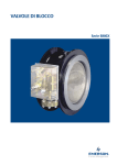
Type OS2
Instruction Manual
NTAOS20007
May 2014
release relay
contents
Release Relay (Type OS2) .......................................... 1 to 3
Introduction ..................................................................
1
Mechanism Box ...........................................................
1
Safety Manometric Box ...............................................
1
Labelling ......................................................................
2
Types of Installation .....................................................
2
Characteristics .............................................................
3
Dimensions and Weights .............................................
3
Mechanism Box (BM) .................................................. 3 to 6
Description and Spare Parts ........................................
3
Operations ...................................................................
4
Connections .................................................................
4
Materials ......................................................................
4
Commissioning ............................................................
4
Maintenance ................................................................
5
Options ........................................................................
5
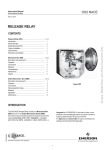
Figure 1. Type OS2
Safety Manometric Box (BMS) .................................... 6 to 12
7
Operation .....................................................................
7
Connections .................................................................
7
Spring Adjustment Range ............................................
8
Materials ......................................................................
10
Adjustment ...................................................................
10
Maintenance ................................................................
12
introDuction
MechanisM BoX (BM)
The mechanism box is designed to close a slam shut valve.
The operation is ensured in two successive stages: a
detection stage and a power stage. The separation between
the detection stage and the power stage provides maximum
precision, indifferent of working pressure, slam shut valve
diameter and gas flow. After activation of the slam shut valve
due to over or under pressure, the mechanism box must
be reset manually. The complete system is available, on
request only, sealed with lead and wire.
The Type OS2 Release Relay consists of a Mechanism Box
(BM) and one or two Safety Manometric Boxes (BMS). Its
function is to provoke the activation of a slam shut valve
which may be stand alone (Type OSE), integrated in a
regulator (Types MP, MPS, DRPNPIL, EZH, DRPN and
EZR) or integrated in a Type K1000/K3000, in the case
of under or over pressure in the controlled gas network. It
may be mounted on systems of DN 25 to DN 150 and up to
PN 100.
safety ManoMetric BoX (BMs)
It is tight shut and submersible. It may be connected to an
explosion-proof contact (intrinsically safe).
In certain configurations, a second box may be used
(Type BMS 2).
TM
The pressure data is transformed into a displacement by
a safety manometric box (Type BMS 1) mounted on the
mechanism box (BM). This displacement is used to
activate the detection stage of the mechanism box in
the case of overpressure, over or underpressure, or
underpressure condition.
D103683X012
Description and Spare Parts ........................................
Type OS2
LABELLING
Taille
BMS Size
See Table 1
Série
N° Serial
PSD BMS
See Table 1
AG maxi
See Table 1
FRANCEL Ressort/Spring Ø
1
bar
Taille
See Table 1
Série
N° Serial
PSD BMS
See Table 1
AG maxi
See Table 1
FRANCEL Ressort/Spring Ø
Wdsu
Wdso
Série
2
PSD BMS
See Table 1
AG maxi
See Table 1
mm
FRANCEL Ressort/Spring Ø
bar
Wdsu
bar
mm
bar
1
Figure 3. Min. Pressure Triggering
bar
mm
1
See Table 1
N° Serial
Figure 2. Max. Pressure Triggering
BMS Size
Taille
BMS Size
bar
Table 1. Type OS2 Pressures
SIZE
162
071
027
017
236
315
PSD
10 bar
20 bar
100 bar
100 bar
35 bar
72 bar
AG max.
2.5
2.5
5
5
2.5
2.5
Figure 4. Max. and Min. Pressure Triggering
See Tables 14, 15 and 16 for other values.
types of installation
Mounting on horizontal pipeline only:
Top Mounted (stand-alone valve)
Bottom Mounted (intergrated valve and regulator)
TYPE BMS 1
BM 1
TYPE BMS 1
N01
BM 1
N03
Figure 5. BM 1: Mechanism Box with
One Safety Manometric Box (Type BMS 1)
Figure 6. BM 1: Mechanism Box with
One Safety Manometric Box (Type BMS 1)
BM 2
TYPE BMS 2
TYPE BMS 1
BM 2
TYPE BMS 1
TYPE BMS 2
N02
N04
Figure 7. BM 2: Mechanism Box with Two Safety
Manometric Boxes (Types BMS 1 and BMS 2)
2
Figure 8. BM 2: Mechanism Box with Two Safety
Manometric Boxes (Types BMS 1 and BMS 2)
Type OS2
characteristics
AG 2.5
Diaphragm or bellows
AG 5
Piston
No memorization
----
4J
(20 shocks)
Accuracy
Memorization
Resistance to vertical shocks
Resistance to pendular shocks
9.81 J
(20 shocks)
Sealing
IP 67
Temporary immersion
100 bar
----
Operating temperature
-30°C to +71°C
----
Maximum valve travel
50 mm
----
Maximum operating pressure (PSD)
dimensions and weigths
A
Table 2. Dimensions and Weights
A
Type
BM
120
134
185
BMS
TYPE
BMS 1
B
TYPE
BMS 2
B
BM1
Dimensions, mm
A
For 1 BMS
BM2
For 2 BMS
162
Diaphragm
B
181
71
Diaphragm
175
36
1.2
Piston
204
36
2.3
236
Bellows
202
36
2.4
315
Bellows
223
36
2.8
1
Figure 9. Dimensions
9
6
2
C B A
3
5
Description and spare parts (bm)
Table 3. Mechanism Box Assembly
1
Cap including indicator, O-ring and screw (new
version 06/2007; interchangeable)
2
Mechanism box casing
New cap O-ring
3
4
5
6
7
8
9
8
N06
Bm1
Bm2
181 067
181 068
4
Figure 10. Mechanism Box for One BMS
181 328
145 430
142 930*
144 071
Box gasket
142 930*
BMS gasket
145 431A*
BMS screw
402 018*
BMS sealing screw O-rings
461 150*
Non-connectable brace vent
27A5516X012
Vent link for 8 x 10 tube
406 526
Yoke
181 042
Fixed bolt axe (do not dismount)
142 920
Bolt
181 043
Truarc O-ring
406 128
Travel stop
140 324
Damper
127 692
Mechanism
181 041
Mechanism screw
402 512
Resetting tool
242 915
* Sold as a set ref. n° 197 351.
Items in bold are spare parts.
2.6
27 or 17
7
Mechanism box
2.5
83
For a Type OS2 with one BMS add the weight of the BMS to that of the BM 1.
For a Type OS2 with two BMS add the weight of the two BMS to that of the BM 2.
N05
Description
2.5
----
166
Item
Weight, kg
N06
Figure 11. Mechanism Box for Two BMSs
connections
Table 4. Connection Types
Non connectable
Plastic vent with screen
Connectable
Link 8/10 tube
Contact
Box exit
1/4" NPT
1/2” NPT
3
Type OS2
Description and spare parts (bm)
VALVE
TRAVEL STOP
4
84
ø 24
D1
1
3
D2
N09
ø 24
N08
N07
Figure 13. Type VSE
Packing Gland
Figure 12. Standard
Packing Gland
Table 5. Packing Gland Assembly
Packing gland
Description
Assembly
Packing gland and stem
Packing gland
O-ring
O-ring
Fastening screw H M7
Fastening screw H M8
Flat washer (7)
Flat washer (8)
Items in bold are spare parts.
Valve
Type OSB
Type VSE
Standard
181 089
181 040
---400 514
---402 028
---405 005
----
181 090
---144 126
400 505
400 221
---402 036
---405 006
181 104
181 040
---400 514
---402 028
402 036
405 005
405 006
operation (BM)
The detection stage consists of two parts:
• The releasing stem (key 1) and
• The 1st stage trigger (key 2).
Through the intermediate of the safety manometric box
(BMS), the pressure provokes a pin movement (D1 or D2),
which provokes the rotation of the releasing stem (key 1)
and frees the 1st stage trigger (key 2).
The power stage consists of two parts:
• The 2nd stage trigger (key 3) and
• The cam (key 4).
The 2nd stage trigger (key 3), activated by the 1st stage trigger
(key 2), frees the cam (key 4), which provokes the valve to
close. After release, the resetting is ensured in two stages:
(detection stage, then power stage) see «commissioning».
Position indicator
The position of the detection stage can be seen through the
position indicator glass.
Memorization
The releasing stem will only start moving when pressure
approaches the pressure setpoint. In all other cases, it remains
fixed. Furthermore the assembly has a very high resistance to
shocks. If pressure approaches the setpoint, the releasing stem
turns, but with the slightest shock or vibration it will go back to its
initial position and pressure returns to normal. The mechanism
is said to be non memorizing.
* The 8/10 tube should be angle-shaped on the top to avoid water from entering.
4
2
Figure 14. Mechanism Details
ø7
Resistance to shocks
This assembly has a remarkable resistance to shocks (20
vertical shocks of 4 J and 20 pendular shocks of 9.81 J),
with pressure close to setpoint (for example: 186 mbar for a
setpoint of 200 mbar).
connections (BM)
• Fixation BM / Connector:
H M7 or H M8 screws
16 N•m torque
• Sealed BM / Connector:
Flat O-ring (water resistant)
Packing gland (gas resistant)
• Mechanism contact / Slam shut valve:
Control rod
• BM connector / atmosphere:
Integrated vent nipple with screen (supplied) or
compression fitting (supplied) for 8/10 tube
(not supplied)*
• Electrical connection:
See page 6
MECHANISM BOX (BM) MATERIAL
Table 6. Mechanism Box (BM) Material
Box
Mechanism
Yoke
O-rings
Body
Aluminum
Chromatation
Cover
Aluminium
Chromatation
Position indicator
Polycarbonate
----
Self-jamming ring
Cover nut
Circlips
All parts
Brackets
Bolt
Elastic O-ring
Steel
Stainless steel
Steel
Stainless HR
Brass
Brass
Steel
Phosphatation
---Phosphatation
Torsion spring
Stainless steel
Traction spring
Bronze
Self-jamming ring
Flat
Cover
Steel
EPDM
Neoprene (CR)
Truarc ring
Nitrile (NBR)
---Phosphatation
---Phosphatation
----
commissioning (bm)
Commissioning differs depending on whether the assembly
has an internal or external bypass and whether overpressure
releasing is required or not. See corresponding technical
manuals for further details.
Type OS2
VALVE
VALVE
VALVE
TRAVEL STOP
TRAVEL STOP
TRAVEL STOP
N10
N11
CLOSED POSITION
RESET DETECTION STAGE
N12
RESET POWER STAGE
Figure 15. Release Activation Stages
maintenance (bm)
Note
The position of the travel stop (Figure 10,
key 7) depends on the type of assembly and
its size. Position A, B or C depending on
max. travel of slam shut valve: A = 15 mm
travel, B = 35 mm travel, C = 50 mm travel.
To access the box the cover must be removed. When
unscrewing the nut a circlips is used to remove the O-ring.
The cover is held on by one screw which can be unscrewed
manually or using a socket screw key (recommended torque
for optimal shutoff: 6 N•m).
• Resetting
To reset the slam shut (after the fault has been settled), the
1st mechanism stage must be reset by manually turning the
1st stage trigger. If the slam shut has an internal bypass the
cam must be slightly turned using a resetting key to bypass.
If the slam shut has an external bypass, a bypass valve will
be used. In both cases:
-- Wait for the pressure to be equalized before resetting
the 2nd mechanism stage.
-- When resetting the 2nd mechanism stage (opening of
the valve) a reset key is used (delete).
Table 7. Packing Gland Material
Bronze
Stainless steel
Nitrile (NBR)
-- Spanner 11 (screw 7) and 13 (or 14) (screw 8)
-- Screwdriver
• Control
• Mechanism box (BM) intervention
Body
Control rod
Truarc ring
• Tools:
---Chromium plating
----
-- 1st and 2nd stage mechanism releasing
-- Packing gland is tight shut
-- Yoke greasing
• Disassembly
-- Check that assembly is not under pressure
-- Manual release of slam shut (Figure 14)
-- Manually press on the releasing stem pin D1 or D2
(Figure 14, key 1) parallel to the BMS axe
-- Unscrew the travel stop (screwdriver)
-- Unscrew the BM fastening screws (flat spanner 11
(screw 7) and 13 (or 14) (screw 8)
-- Disassemble the mechanism box (BM) from the
connector by unlocking the yoke
• Assembly
-- Proceed in reverse order to disassembly
options (bm)
• Remote alert (on BM1 or BM2)
Detects 2nd stage releasing (power)
caution
Never use an extension pipe with the reset key
when resetting the 2nd stage (max. normal
torque 16 N•m, never go over 32 N•m).
!
Warning
AUTHORIZED PERSONNEL ONLY
Risk of injury
After rearming, remove the reset key from
the stem. Do not put fingers in or near the
reset mechanism area.
• Remote control
Atmospheric solenoid valve (releasing by min. pressure)
for max. releasing pressure of 30 bar. Safety manometric
box (BMS) activated with a pneumatic or electropneumatic impulse.
• Manual control on BM2 with 1 Type BMS 1 only
Push button (connected at the same place as a
Type BMS 2).
5
Type OS2
Contact
Table 8. Mechanism Box (BM) Connections
AC
7.0 A
400 V
Max. intensity
Max. tension
Protection
Tightness
Temperature
Fastening
Cable
DC
0.8 A
250 V
EEx-d IIC T6
IP 66
-29°C +71°C
2 M3 screws
3 wires (black, brown, blue) H05VVF (3 x 0.75 mm²) D 6.5 mm
Table 9. Mechanism Box (BM) Versions
Version
Installation
Sealing
Connection
Mechanical Connection
C0
C1
C2
C3
----
IP 68
IP 68
IP 68
IP 68
Without
1/2 NPT cap
3 m wire
Explosion proof connector box/PE explosion proof
Intrinsical safe tight-shut connector
Explosion proof
Intrinsical safe
Explosion
proof
N13
Electrical connections
NF
NO
---Blue
Brown
4
5
B
C
Common
Black
3
A
N14
WIRING
N15
WIRING
WIRING
BU
BK
NF --> BK/BU
NO --> BK/BNBU
BK
BN
Wires
Screwed wiring
Welded wiring
3m
WIRING
BN
BK
Connection
NF : Normally closed
NO: Normally opened
BU
BU
BK
BN
BN
C
A
123456
NF --> BK/BU
NO --> BK/BN
B
NF --> BK(3)/BU(4)
NO --> BK(3)/BN(5)
NF --> BK(A)/BU(B)
NO --> BK(A)/BN(C)
Version C2 connection
Explosion proof connection
with explosion proof connector box
Version C1 connection
Explosion proof connection with cable
and tight-shut packing gland
Version C3 connection
Explosion proof connection
with sealed connector for intrinsic safe
Figure 16. Different Versions of BM Connections
safety manometric box (bms) description and spare parts
SAFETY
MANOMETRIC
BOX (BMS)
BASE
SAFETY
MANOMETRIC
BOX (BMS)
BASE
SAFETY
MANOMETRIC
BOX (BMS)
BASE
SAFETY
MANOMETRIC
BOX 1 (TYPE BMS 1)
“HOOK” KIT
SAFETY
MANOMETRIC
BOX 1 (TYPE BMS 1)
“HOOK” KIT
SAFETY
MANOMETRIC
BOX 1 (TYPE BMS 1)
“HOOK” KIT
SAFETY
MANOMETRIC
BOX 2 (YPE BMS 2)
“HOOK” KIT
SAFETY
MANOMETRIC
BOX 2 (TYPE BMS 2)
“HOOK” KIT
SAFETY
MANOMETRIC
BOX 2 (TYPE BMS 2)
“HOOK” KIT
N16
Figure 17. BMS with Diaphragm
6
N17
Figure 18. BMS with Piston
N18
Figure 19. BMS with Bellows
Type OS2
Table 10. Spare Parts
Diaphragm (Max. and/or Min.)
Description
Piston (Max. or Min.)
71
27
17
236
315
Compete box
181 071
181 072
180 999
180 998
181 073
181 074
Base
181 105
181 106
181 107
181 108
181 109
181 110
Type BMS 1
Hook kit
181 111
Compete box
181 084
181 085
181 070
181 069
181 086
181 087
Base
181 105
181 106
181 107
181 108
181 109
181 110
----
----
Type BMS 2
Hook kit
181 112
137 906
Diaphragm
Spare Parts
Bellows (Max. and/or Min.)
162
Set of O-rings
142 549
---197 352
----
-------
Items in bold are spare parts.
Description (bms)
• Impulse line
The impulse line (IS) is connected to the network to be
protected (normally downstream of the regulator).
• Impulse type
N19
Depending on the pressure and precision required,
different types of impulse may be used: Diaphragm, Piston
or Bellows.
Figure 20. Type BMS 1 Max. Only
D2
• Springs
To cover all pressure ranges, a set of springs of equal
length and diameter, but of different wire diameter (2 to
6.5 mm), may be used.
D1
• Detection
N20
Table 11. Detection Configurations
One
BMS
Two
BMS
Actioner
Max. only
Min. only
Max. and Min.
Type
BMS 1
Releasing screw
Active
Neutral
Active
Hook
Neutral
Active
Active
Type
BMS 1
Releasing screw
Active
Hook
Neutral
----
----
Type
BMS 2
Push button
Active
Neutral
Active
Hook
Neutral
Active
Active
Figure 21. Type BMS 1 Min. Only
D2
D1
N21
operation (bmS)
The pressure of the network to be protected pushes the
diaphragm, piston or bellows. The force resulting from this
opposes the force (adjustable) coming from the setpoint
spring. When pressure varies, the detection rod moves and
provokes releasing by max. or min. pressure.
connections (bmS)
On the mechanism box:2 H M6x16 screws
(code 402018)
BM sealing:Flat O-ring and tight shut O-rings
On the manometric box:
1/4" NPT screw
Recommended tube:
8/10 mm
The sensing line must be connected downstream of
the regulator.
Figure 22. Type BMS 1 Max. - Min.
Table 12. Max. Pressure Releasing
Type BMS 1
Type BMS 2
Releasing screw
Push button
Normal
Without D1 pin contact
Without D2 pin contact
Increase
With D1 pin contact
With D2 pin contact
Pressure
= Setpoint
Rotation of releasing stem and 1st stage trigger
Table 13. Min Pressure Releasing
Pressure
Type BMS 1
Type BMS 2
Hook
Hook
Normal
Without D2 pin contact
Without D1 pin contact
Decrease
With D2 pin contact
With D1 pin contact
= Setpoint
Rotation of releasing stem and 1st stage trigger
7
Type OS2
spring adjustments ranges (bmS)
(See definitions on page 9)
Table 14. Max. Only Spring Adjustment Ranges
BMS
SPRING
MAX. ONLY
Intervals
∆1
Wdso setting, bar
Type
Size
162
PMS box
(bar)
10
Diaphragm
MAX. ONLY
071
027
20
100
Piston
Bellows
017
100
236
35
315
72
ø Wire
(mm)
Code
Recommended range
Max. low
point
possible
Max. low
point
Max. high.
point
∆1
(bar)
2.0
113 195
0.010
0.015
0.035
0.004
2.5
113 196
0.025
0.040
0.080
0.005
3.0
113 197
0.045
0.080
0.140
0.010
3.5
113 198
0.070
0.070
0.240
0.014
4.0
113 199
0.115
0.140
0.380
0.018
5.0
113 201
0.140
0.300
0.750
0.050
5.5
113 202
0.250
0.600
1.3
0.080
6.5
114 139
0.450
1.2
2.3
0.170
4.5
113 200
1.0
2.0
5.1
0.350
5.5
113 202
2.1
4.0
11.0
0.700
6.5
114 139
4.0
8.0
16.0
1.6
5.5
113 202
16.0
16.0
22.0
3.0
6.5
114 139
22.0
22.0
40.0
6.5
5.5
113 202
40.0
40.0
55.0
7.0
6.5
114 139
55.0
55.0
100.0
12.0
5.5
113 202
5.5
11.0
22.0
1.6
6.5
114 139
8.3
16.0
35.0
2.5
5.0
113 201
17.5
35.0
72.0
5.0
Table 15. Min. Only Spring Adjustment Ranges
BMS
SPRING
MIN. ONLY
Intervals
∆1
Wdsu setting, bar
Type
Size
162
PMS box
(bar)
10
Diaphragm
MIN. ONLY
071
20
027
100
017
100
236
35
315
72
Piston
Bellows
8
ø Wire
(mm)
Code
Min. low
point
possible
Recommended range
Min. low
point
Min. high.
point
∆1
(bar)
2.0
113 195
0.010
0.015
0.035
0.004
2.5
113 196
0.025
0.040
0.080
0.005
3.0
113 197
0.045
0.080
0.150
0.010
3.5
113 198
0.070
0.070
0.240
0.014
4.0
113 199
0.115
0.150
0.400
0.018
5.0
113 201
0.140
0.300
0.650
0.050
5.5
113 202
0.250
0.600
1.15
0.080
6.5
114 139
0.450
1.1
2.0
0.170
4.5
113 200
1.0
2.0
4.7
0.350
5.5
113 202
2.1
4.0
9.5
0.700
6.5
114 139
4.0
8.0
14.4
1.6
5.5
113 202
16.0
16.0
19.0
3.0
6.5
114 139
19.0
19.0
38.0
6.5
5.5
113 202
38.0
38.0
50.0
7.0
6.5
114 139
50.0
50.0
90.0
12.0
5.5
113 202
5.5
11.0
16.0
1.6
6.5
114 139
8.3
16.0
28.0
2.5
5.0
113 201
17.5
28.0
65.0
5.0
Type OS2
Table 16. Max. and Min. Spring Adjustment Ranges
BMS
SPRING
MAX. and MIN.
Intervals
∆1 and ∆2
Wdsu setting (bar)
Type
Size
162
PMS box
(bar)
10
Diaphragm
MAX. and
MIN.
071
Piston
Bellows
20
ø Wire
(mm)
Code
Min. low
point
possible
Max. high
point
∆1
(bar)
∆2
(bar)
2.0
113 195
0.010
0.035
0.004
0.010
2.5
113 196
0.025
0.080
0.005
0.025
3.0
113 197
0.045
0.140
0.010
0.050
3.5
113 198
0.070
0.240
0.014
0.060
4.0
113 199
0.115
0.380
0.018
0.150
5.0
113 201
0.140
0.750
0.050
0.350
5.5
113 202
0.230
1.3
0.080
0.600
6.5
114 139
0.450
2.3
0.170
1.1
4.5
113 200
1.0
5.1
0.350
2.5
5.5
113 202
2.1
11.0
0.700
5.5
6.5
114 139
4.0
16.0
1.6
10.0
027
Not possible with only 1 BMS
017
236
35
315
72
definitions
5.5
113 202
5.5
16.0
1.6
10.0
6.5
5.0
114 139
8.3
28.0
2.5
20.0
113 201
17.5
65.0
5.0
33.0
Table 17. Definitions
PSD box
Maximum operating pressure for box
Pd
Nominal downstream regulator pressure
Pd max
Maximum downstream regulator pressure (normally closing regulator pressure)
Pd min
Minimum downstream regulator pressure (disturbance in function with flow and/or inlet pressure is to be considered)
Pdo
Maximum releasing pressure
Max. high point
High regulator pressure at maximum
Max. low point
Low regulator pressure at maximum remaining within the accuracy class
Max. low point possible
Low regulator pressure at furthest maximum point (precision is not guaranteed)
Pdu
Minimum releasing pressure
Min. high point
High minimum regulator pressure
Min. low point
Low regulator pressure at minimum remaining within the accuracy class
Min. low point possible
Low regulator pressure at furthest minimum point (precision is not guaranteed)
Wdso
Overpressure specific range obtained from slam shut valve
Wdsu
Underpressure specific range obtained from slam shut valve
∆1
Minimum difference allowed between Pdo and Pd max. and/or between Pdu and Pd min.
∆2
Maximum difference allowed between maximum and minimum releasing pressure
Selection guide lines: pressure limitations
Table 18. Pressure Limitations
Max. Only
Pdo ≤ PMS box (BMS)
Pdo ≤ Max. high point
Pdo ≥ Max. low point
Pdo ≥ Pd max. + ∆1
Min. Only
Pd max. < PMS box (BMS)
Pdu ≤ Max. high point
Pdu ≥ Min. low point
Pdu ≥ Pd min. -∆1
Max. and Min.
Pdo ≤ PMS box (BMS)
Pdo ≤ Max. high point
Pdo ≥ Pd max. + ∆1
Pdu ≥ Min. lowest point possible
Pdu ≤ Pd min. - ∆1
Pdu - Pdu ≤ ∆2
9
Type OS2
Note
When the setpoint (max. or min.) falls
between the lowest and lowest point
possible, the precision may pass into a
superior range (example AG 2.5 —> AG 5). If
the point value is too close to that of the Pd,
the option RJGI tripping is recommended
(consult factory). In the case of two safety
manometric boxes (BMS) both boxes should
have a PSD > to the highest Pdo.
Selection of BMS and SPrings
Choose the type of safety manometric box (BMS) according
to: PMS, the type of releasing precision.
Choice of springs:
• Max. or Min. only
Take the spring with the highest point directly superior to
the releasing pressure required.
• Max. and Min.
Take the spring with the highest maximum point superior to
the maximum releasing pressure required or with the lowest
point inferior to the minimum tripping pressure required.
Table 19. Choice of BMS and Springs
PSD
Diaphragm
Bellows
Piston
0 to 20
20 to 72
(*)
72 to 100
AG 2.5
AG 5
Max. only
Min. only
Max. and Min.
(*) Choice between piston (regular) and bellows (optional). Bellows are recommended
if you require a small gap between releasing pressure, inlet pressure and exact
precision. Pistons do not facilitate minimum and maximum releasing.
materials (BMS)
Spring case
Spring box
Diaphragm
Piston
Bellows
Spring
Adjustment screw
Piston
Stainless steel
Stainless steel
Stainless steel
Zinc-plated steel
Zinc-plated steel
!
Generally speaking, adjustments are carried out with the slam
shut valve closed. Only the detection stage is reset. Control of
the releasing value may be obtained by resetting the two stages.
caution
Before any adjustment, check that the
spring range installed corresponds to the
required setpoint.
Y
2
1
6
7
Warning
AUTHORIZED PERSONNEL ONLY
Risk of injury
After rearming, remove the reset key from
the stem. Do not put fingers in or near the
reset mechanism area.
5
4
D2
X=d
istance between releasing
screw and pin D1
Y = distance between releasing
screw and pin D2
D1
X
N22
Type BMS 1 (Figures 17 to 19)
Releasing by Max. Only
• Adjusting the releasing screw Free the min. hook (key 2).
Then in the following conditions:
-- no pressure in the safety manometric box (BMS),
-- setpoint spring compressed so that the distance
between the releasing screw and the pin D1 no longer
increases, adjust the releasing screw (key 1) to
X = 1.5 mm (detection stage set). Jam nut (key 3).
• Adjusting the max. only releasing pressure
Admit the releasing pressure to Pdo.
Screw the adjustment screw (key 5) until detection stage
can be set.
Unscrew the adjustment screw (key 5) until detection
stage release.
Check the pressure value at the releasing point
(adjust if necessary).
Jam nut (key 4).
• Adjusting the releasing screw and hook
Free the min. hook (key 2).
Then in the following conditions:
-- setpoint spring decompressed (adjustment screw
(key 5) unscrewed),
-- pressure equal to the releasing pressure required for
Pd min in the BMS,
adjust the releasing screw (key 1) to X = 2 mm (detection
stage set).
Jam nut (key 3).
Put the hook (key 2) into position and adjust Y = 1.5 mm
with nuts (key 6) and (key 7).
Jam nuts (key 6) and (key 7).
• Adjusting the min. only releasing pressure
Continue admitting the required releasing pressure. Screw
the adjustment screw (key 5) until detection stage release.
Check the pressure value at the releasing point
(adjust if necessary). Jam lock nut (key 4).
10
3
Releasing by Min. Only
Table 20. BMS Material
Diaphragm
Bellows
Zinc-plated steel
Aluminum + Chromatation
Nitrile mesh
adjustment (BMS)
Type OS2
Releasing by Max. and Min. (Diaphragms
or Bellows Only)
• Adjusting the releasing screw
Free the min. hook (key 2).
Then in the following conditions:
-- setpoint spring decompressed (adjustment screw
(key 5) unscrewed),
-- pressure equal to the max. releasing pressure required
in the BMS,
adjust the releasing screw (key 1) to X = 0 mm (detection
stage set).
Release manually.
Unscrew the releasing screw (key 1) 2 turns, which
represents a distance of approximately 1.5 mm.
Jam nut (key 3).
• Max. adjustment
Same procedure as paragraph “Adjusting max. only
releasing pressure”
• Min. adjustment
Admit an average pressure between max. and min.,
(for example: regulator set-point pressure).
Set the slam shut.
Admit a pressure equal to the min. Pd min. releasing
pressure required.
Adjust the hook (key 2) by progressively moving nuts
(key 6) and (key 7) until it releases.
Jam nuts (key 6) and (key 7).
Check the pressure value at the releasing point (adjust
if necessary).
Type BMS 2 with 1 Max. Only Type BMS 1
Releasing by Max. Only
• Adjusting the max. push button
Remove the hook (key 2).
Then in the following conditions:
-- no pressure in the BMS,
-- setpoint spring compressed so that the distance
between the push button (key 1) and the pin D2 no
longer increases,
Adjust the push button (key 1) to X = 1.5 mm (detection
stage set).
Jam nut (key 3).
4
5
3
1
X
D2
MAX. ONLY TYPE BMS1
ADJUSTMENT
• Adjusting the max. only releasing pressure
Same procedure as paragraph “Adjusting the max. only
releasing pressure”.
Releasing by Min. Only
• Adjusting the min. only releasing pressure
Remove the max. push button (key 1) or screw it tight to
neutralize it.
Jam nut (key 3).
Then in the following conditions:
-- setpoint spring decompressed (adjustment screw
(key 5) unscrewed),
-- pressure equal to releasing pressure required in the
BMS, adjust the min. hook (key 2) to Y = 1.5 mm
(detection stage set).
Jam nut (key 6).
• Adjusting the min. only releasing pressure
Same procedure as paragraph “Adjusting max. only
releasing pressure”.
Releasing by Max. and Min.
• Adjusting the push button
The min. hook (key 2) is completely unscrewed.
Then in the following conditions:
-- setpoint spring decompressed (adjustment screw
(key 5) unscrewed),
-- pressure equal to the max. releasing pressure required
in the BMS.
adjust the push button (key 1) to X = 0 mm
(detection stage set).
Release manually.
Unscrew the push button (key 1) 2 turns, which represents
a distance of approximately 1.5 mm.
Jam nut (key 3).
• Adjusting the releasing pressure to max. and min.
Max. adjustment
Same procedure as paragraph “Adjusting the max. only
releasing pressure”.
Min. adjustment
Admit an average pressure between max. and min.,
(for example regulator set-point pressure).
Set the detection stage.
Admit a pressure equal to the min. releasing
pressure required.
Screw the hook (key 2) progressively until detection
stage release.
Jam nut (key 6).
Check the pressure value at the releasing point
(adjust if necessary).
D1
Y
N23
6
2
11
Type OS2
Maintenance (bms)
• Control
The safety valve and pressure accessories are subject
to normal wear and must be inspected periodically and
replaced if necessary.
-- Slam shut releasing
-- External tight shut
-- Impulse part (diaphragm, bellows or piston)
The frequency of inspections, checks and replacement
depends on the severity of service conditions and must
comply with the national or industrial codes, standards
and regulations/recommendations applicable.
• Disassembly
-- Unscrew the connector form the sensing line
-- Remove the safety manometric box (BMS)
-- Unscrew the blocking nut on the adjustment
screw (manually)
-- Unscrew the adjustment screw (resetting tool)
-- Remove the hook or plate, depending on the type of
Type BMS 1 or 2, from the detection rod
(flat spanner 7)
-- Remove the upper case
BMS 162 (flat spanner 11)
BMS 071 (flat spanner 8)
BMS piston 27/17 (key 5)
BMS bellows 236/315 (key 5)
-- Disassemble the set plate/counter plate (flat spanner 17
and pliers) or
-- Remove the bellows or piston and guide (manually)
• Assembly
-- Proceed in reverse order to disassembly
• BMS torque values
-- Upper spring case/manometric box
BMS 162:
BMS 071:
BMS piston 27/17:
BMS bellows 236/315: -- BMS 162 and 071 nut/diaphragm plate:
8 N•m
5 N•m
6 N•m
6 N•m
20 N•m
Industrial Regulators
Natural Gas Technologies
TESCOM
Emerson Process Management
Regulator Technologies, Inc.
Emerson Process Management
Regulator Technologies, Inc.
Emerson Process Management
Tescom Corporation
USA - Headquarters
McKinney, Texas 75070, USA
Tel: +1 800 558 5853
Outside U.S. +1 972 548 3574
USA - Headquarters
McKinney, Texas 75070, USA
Tel: +1 800 558 5853
Outside U.S. +1 972 548 3574
USA - Headquarters
Elk River, Minnesota 55330-2445, USA
Tels:+1 763 241 3238
+1 800 447 1250
Asia-Pacific
Shanghai 201206, China
Tel: +86 21 2892 9000
Asia-Pacific
Singapore 128461, Singapore
Tel: +65 6777 8337
Asia-Pacific
Shangai 201206, China
Tel: +86 21 2892 9499
Europe
Bologna 40013, Italy
Tel: +39 051 419 0611
Europe
O.M.T. Tartarini s.r.l. Via P. Fabbri 1,
I-40013 Castel Maggiore (Bologna), Italy
Tel: +39 051 419 0611
Francel SAS, 3 ave Victor Hugo,
CS 80125 - Chartres 28008, France
Tel: +33 2 37 33 47 00
Europe
Selmsdorf 23923, Germany
Tel: +49 38823 31 287
Middle East and Africa
Dubai, United Arab Emirates
Tel: +011 971 4811 8100
Middle East and Africa
Dubai, United Arab Emirates
Tel: +011 971 4811 8100
For further information visit www.emersonprocess.com/regulators
The Emerson logo is a trademark and service mark of Emerson Electric Co. All other marks are the property of their prospective owners. Francel is a mark of Francel SAS, a business of Emerson
Process Management.
The contents of this publication are presented for informational purposes only, and while every effort has been made to ensure their accuracy, they are not to be construed as warranties or guarantees,
express or implied, regarding the products or services described herein or their use or applicability. We reserve the right to modify or improve the designs or specifications of such products at any
time without notice.
Emerson Process Management does not assume responsibility for the selection, use or maintenance of any product. Responsibility for proper selection, use and maintenance of any Emerson Process
Management product remains solely with the purchaser.
O.M.T. Officina Meccanica Tartarini S.R.L., R.E.A 184221 BO Cod. Fisc. 00623720372 Part. IVA 00519501209 N° IVA CEE IT 00519501209,
Cap. Soc. 1.548 000 Euro i.v. R.I. 00623720372 - M BO 020330
Francel SAS, SIRET 552 068 637 00057 APE 2651B, N° TVA : FR84552068637, RCS Chartres B 552 068 637, SAS capital 534 400 Euro
©Emerson Process Management Regulator Technologies, Inc., 2007, 2014; All Rights Reserved