1
Instruction Manual
NTAEZH0811
Types EZH and EZHSO
November 2008 - Rev. 06
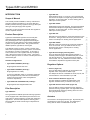
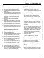
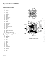
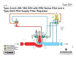
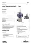
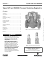
Types EZH and EZHSO Pressure Reducing Regulators
Contents
Introduction ........................................................................ 2
Characteristics ................................................................... 3
Labelling ............................................................................ 5
Description ......................................................................... 8
Principle of Operation ......................................................... 8
Monitoring Systems ............................................................ 11
Installation ......................................................................... 13
Startup and Adjustment ..................................................... 15
Shutdown ........................................................................... 16
Maintenance ...................................................................... 17
R94
Troubleshooting ................................................................. 24
Spare Parts ........................................................................ 25
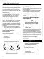
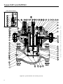
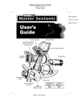
Figure 1. Type EZH Pressure Reducing Regulator
Parts List ............................................................................ 26
!
WARNING
Failure to follow these instructions or to
properly install and maintain this equipment
could result in an explosion and/or fire
causing property damage and personal
injury or death.
Fisher® regulators must be installed,
operated, and maintained in accordance
with federal, state, and local codes, rules
and regulations, and Emerson Process
Management Regulator Technologies, Inc.
(Regulator Technologies) instructions.
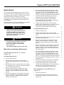
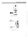
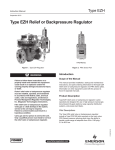
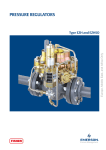
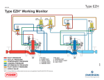
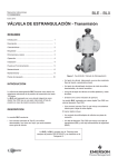
TYPE PRX-120
TYPE PRX-120/AP
Figure 2. PRX Series Pressure Reducing Pilots
If the regulator vents gas or a leak develops
in the system, service to the unit may be
required. Failure to correct trouble could
result in a hazardous condition.
Call a gas service person to service the
unit. Only a qualified person must install or
service the regulator.
Types EZH, EZHSO, EZH OS2, and EZHSO OS2
regulators are in conformity with the
Pressure Equipment Directive
PED 97/23/EC and are classified in Category IV.
www.fisherregulators.com
Europe, Middle East, and Africa Document Only
Dimensions and Weights ................................................... 6
Types EZH and EZHSO
Scope of Manual
This manual provides installation, startup, maintenance,
and parts ordering information for the Types EZH and
EZHSO pressure-reducing regulators and Type PRX pilot
with Type SA/2 pilot supply filter regulator.
Information on other equipment used with this regulator is
found in separate manuals.
Product Description
• Type PRX/120:
Outlet pressure range of 1 to 40 bar. The Type PRX/120
can be used as the pilot on single stage pressure reducing
regulators, as the monitor pilot, or as the working pilot in
wide-open monitor systems.
• Type PRX/120-AP:
Outlet pressure range of 30 to 80 bar. The Type PRX/120-AP
can be used as the pilot on single stage pressure reducing
regulators, as the monitor pilot, or as the working pilot in
wide-open monitor systems.
• Type PRX/125:
Identical to the Type PRX/120, except the restriction screw
is removed. The Type PRX/125 can only be used as the
monitor override pilot on working monitor applications.
Types EZH and EZHSO regulators are accurate pilotoperated pressure balanced, soft-seated regulators.
They are designed for use in high pressure natural gas
transmission/city gate stations, large capacity distribution
systems, and power plant feeds. They provide smooth,
reliable operation, tight shutoff, and long life.
• Type PRX/125-AP:
Type EZHSO "Spring-to-Open" version could be used
when other overpressure protection options are foreseen,
for example in a monitor configuration. In this case, in
event of failure, the main regulator will stay completely
open, allowing the monitor to take control. The monitor
could be "Spring-to-Close" to ensure a double protection to
downstream pipe.
• Type SA/2 Pilot Supply Filter Regulator:
Available Configurations:
• Types EZH and EZHSO ("E Body")
Single regulator without slam shut
• Types EZH and EZHSO ("X Body")
Single regulator in a X Body
In case of modification made on a pressure equipment
like cap replacement by a slam shut it's mandatory to
comply to the local codes, rules and regulations.
Contact us imperatively.
• Types EZH OS2 and EZHSO OS2 ("X Body")
Single regulator with integrated slam shut
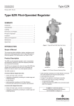
Pilot Description
Type PRX Pilot
The Types EZH and EZHSO pressure-reducing regulators
can be equipped with a PRX Series pilot mounted on the
main valve for pressure reducing or wide-open monitoring
applications. The PRX Series pressure reducing pilots
have the ability to handle a wide range of setpoints from
1 to 80 bar:
2
Identical to the Type PRX/120-AP, except the restriction
screw is removed. The Type PRX/125-AP can only
be used as the monitor override pilot on working
monitor applications.
The Type SA/2 pilot supply filter regulator provides a
constant pressure supply to the PRX Series pilot of 3 bar
over the set pressure. The Type SA/2 has an integral
5-micron filter. For easy maintenance a block valve can
be installed to separate the regulator from the pilot.
Regulator Options
• Silencer (Figure 22)
The Type EZH silencer (Whisper III) is integrated in the
regulator and is composed of a drilled cage.
The Whisper III silencer is available for DN 25, 50, 80, and
100 and allows a noise attenuation up to 8dB.
• Flow Coefficient Reduction (Figure 16)
The flow reduction is realised by replacement of the
regulator standard seat by a reduction seat ( key 2).
• Type RPE Electrical Pilot Heater (Figure 25)
The Type RPE is used for reheating the gas supplying
pressure reducing regulator pilots. The Type RPE avoids
the inconveniences caused by freezing which can occur
during high pressure drops.
Actuator
The actuator is an integral pressure type. All pressure parts
are designed to resist up to 100 bar. The diaphragm is
strong and can resist to a differential of 100 bar.
Europe, Middle East, and Africa Document Only
INTRODUCTION
Types EZH and EZHSO
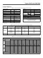
CHARACTERISTICS
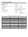
Table 1. General Characteristics for Types EZH and EZHSO Regulator
SLAM SHUT
A352LCC Body, Actuator, Valve,
Pilot Body, Slam shut
PS
EN 14382
European EN Standard
100 bar max
A or B (see Figure 3)
Operation Class
Associated BMS(1), according to size
PSD
10 to 100 bar
Type
IS
Integral strength(4)
OPERATING TEMPERATURE(2)
TS
-20 / 60°C Class 2
Sizes available
DN
25, 50, 80, and 100
Noise level reduction
Up to 8 dB
DP max
Maximum Operating Differential
Diaphragm,
Bellows
Accuracy
Up to ±2.5%
Up to ±5%
Piston
EN 334
European EN Standard
Pu
2 to 100 bar
Outlet Pressure
Pd
1 to 80 bar
Minimum Differential
DP min
1 bar (Type EZH)
3.8 bar (Type EZHSO)
Maximum Differential
DP max
99 bar (Type EZH)
96.2 bar (Type EZHSO)
Accuracy (optimal)
AC
See Table 2
Lock-Up Pressure Class
SG
Up to 5%(3)
Lock-Up Pressure Zone Class
SZ
Up to 5%(3)
(1) BMS - Safety Manometric Box
(2) Standard version
<1 s
AG
Wdu-Wdo
Set Pressure Range
REGULATOR
Inlet Pressure
100 bar
ta
Response Time
0.010 / 100 bar
Flow Coefficient
Qf
13
Internal Automatic Bypass
Cg
25
Rearming
Manual after rectification of fault
Position Indicator
On mechanism box
Fluid
Groups 1 and 2 according to PED 97/23/EC, Gas 1st and 2nd family according to
EN 437, or other gases (compressed air, nitrogen).
The gas must be non corrosive, clean
(filtration on inlet side necessary) and dry.
(3) Contact us with your operating conditions
(4) Depending on BMS configuration for Type EZH OS2
Table 2. Outlet Pressure Ranges, Accuracy Class, and Pilot Spring Information
TYPE
AC (ACCURACY CLASS)
PILOT CONTROL SPRING INFORMATION
OUTLET PRESSURE
ADJUSTMENT RANGES (bar)
TYPE EZH
TYPE EZHSO
Spring Colour
1.0 to 1.8
1.8 to 3.0
3.0 to 5.5
5.5 to 8.5
2.5%
2.5%
2.5%
2.5%
2.5%
2.5%
2.5%
2.5%
Yellow
Green
Blue
Black
8.5 to 14.5
14.5 to 23.0
23.0 to 30.0
30.0 to 40.0
1%
1%
1%
1%
2.5%
2.5%
2.5%
2.5%
Silver
Gold
Aluminium
Red
30.0 to 80.0
1%
2.5%
Clear
PRX/120 and
PRX/125
PRX/120-AP and
PRX/125-AP
R95
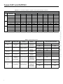
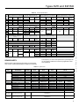
Table 3a. 2:1 Line Flow Coefficients, Regulator, and Slam-Shut Travel
TYPES EZH (DN 25 - 100) AND EZHSO (DN 25 - 100)
WITH SLAM SHUT (X BODY)
WITHOUT SLAM SHUT (E BODY)
REDUCTION
Qf
Cg
C1
DN 25
DN 50
DN 80
DN 100
DN 25
DN 50
DN 80
DN 100
0
284
1078
2247
3567
280
1088
2266
3696
1
210
908
1684
2969
218
829
1698
2902
2
126
671
1058
1763
128
607
1066
1784
3
79
385
685
1062
81
370
690
1072
0
550
2092
4359
6920
544
2110
4396
7170
1
408
1762
3266
5760
423
1609
3294
5630
2
245
1301
2052
3420
249
1177
2069
3460
3
154
746
1328
2060
157
718
1339
2080
0
31.3
38.3
30.8
32.5
35.5
33.5
30.8
31.4
1
34.3
35.3
33.9
35.3
38.7
31.9
33.9
34.2
2
33.6
38.8
37.8
37.3
39.7
35.6
37.8
36.3
3
32.1
40.8
33.6
37.1
39.1
38.2
33.6
37.3
25
30
9
17
25
30
30
50
Regulator travel (mm)
Slam-shut travel (mm)
9
17
15
R96
3
Europe, Middle East, and Africa Document Only
OPERATING PRESSURE
Types EZH and EZHSO
Table 3b. 2:1 Line Flow Coefficients, Regulator with Integrated Whisper III Silencer
TYPES EZH (DN 25 - 100) WITH WHISPER III AND EZHSO (DN 25 - 100) WITH WHISPER III
SLAM SHUT INTEGRATED (X BODY)
WITHOUT SLAM SHUT (E BODY)
Qf
Cg
C1
DN 25
DN 50
DN 80
DN 100
DN 25
DN 50
DN 80
DN 100
0
223
781
1693
2742
255
793
1708
2789
1
215
764
1418
2479
209
716
1172
2438
2
140
603
975
1644
127
566
984
1711
3
87
370
685
1041
81
358
690
1057
0
433
1516
3285
5320
495
1539
3313
5410
1
417
1482
2751
4810
406
1389
2774
4730
2
273
1169
1892
3190
247
1099
1908
3320
3
168
718
1328
2020
158
695
1339
2050
0
35.5
37
30.8
31.7
33.8
33.5
30.8
30.4
1
35.4
37.5
33.6
34.1
39.4
34.1
33.6
32.4
2
32.3
39.5
37.1
36.4
39.9
35.7
37.1
35.7
3
32.9
39.4
38.3
37.6
39.9
37.7
38.3
37.3
Europe, Middle East, and Africa Document Only
REDUCTION
Table 4. Failure Mode Analysis
PART NAME
FAILURE
(WORST CASE)
CAUSE OF
FAILURE
EFFECT
REGULATOR TYPE
Filter blocked/
clogged
Debris or aromatics
present in the gas
Decrease of feeding
pressure gives
decrease of
motorization pressure
EZHSO
Open
---
Filter
EZH
---
Close
Pilot cannot be closed
Debris or aromatics
present in the gas
Increase
motorization
pressure
EZHSO
Open
---
EZH
Open
---
EZHSO
Open
---
EZH
---
Close
EZHSO
Open
---
EZH
---
Close
EZHSO
Open
---
EZH
---
Close
EZHSO
---
Close
EZH
---
Close
Pilot Disk
Pilot Lower
Diaphragm
Pilot cannot control
Debris or aromatics
present in the gas
Decrease
motorization
pressure
Pilot Upper
Diaphragm
Pilot cannot feed
the regulator
Debris or aromatics
present in the gas
Decrease
motorization
pressure
Regulator
Diaphragm
Not proper
performance of
the motorization
pressure chamber
Debris or aromatics
present in the gas
Balancing of
pressures and charge
or discharge of
the motorization
pressure chamber
Pilot
Frozen Pilot,
Type SA/2 working
Moisture in the gas,
high pressure drop
Type SA/2 loading
upper casing of
regulator, Pilot
not supplying
loading pressure
to lower casing
REGULATOR REACTION MODE
R96B
4
Types EZH and EZHSO
Inlet/Outlet :
Material
CL150 RF - CL300 RF - CL600 RF
PN 16B - PN 25B - PN 40B
Other configurations available
(contact factory)
Body:
Steel
Connecting parts and bottom:
Steel
Actuator:
Steel
Stainless steel
Pilot feed:
1/4’’ NPT female
Regulator/Slam-shut orifice:
Pilot Reject:
1/4’’ NPT female
Regulator valve plug:
Stainless steel
Pilot impulse:
1/4’’ NPT female
Slam-shut valve plug:
Stainless steel
Slam-shut impulse:
1/4’’ NPT female
BM* vent:
1/4’’ NPT female
Regulator plug disc/
Slam-shut O-rings:
Impulse tube diameter:
Interior Ø 8/10 mm
Contact switch:
See NTAOS2
Nitrile (NBR) or
Fluorocarbon (FKM)
Europe, Middle East, and Africa Document Only
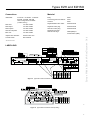
Connections
* BM - Mechanism Box
LABELLING
Security Class
A
B
BMS 027/017 BMS 162
BMS 236/315 BMS 071
All
types of BMS
BMS Setting
Max only
OS2
Min only
Max-Min
-
Standard EN 14382 -
EZH EZHSO
SECURITE/SLAM SHUT
GROUPE 1 (Gaz Naturel) Cat IV PS
série
bar
DD MM YEAR
Date Fab/Test
Mfg/Test date
N° serial
50 80 100
CL300 RF
PN25B
Failure mode FC FO
norme
standard
norme
standard
REGULATEUR/REGULATOR
DN 25
CL150 RF
PN16B
Other configurations available (contact factory)
mode défaillance
failure mode
classe sécurité
slam shut class
EN 334
bar Temp TS -20/+60°C
PT
matériau
shell
DN
FISHER
PN
Pumax
FRANCEL
28320 Gallardon-France
bar
Class 2 Type
Cg
0062
A352LCC+A350LF2
Reduction
Cg
IS
DS
CLASS
150 300 600
Pumax 18.9 50 100
PT
32 79 158
PS 18.9 50 100
PS
CL600 RF
PN40B
16B
16
26
16
0
1
2
3
See Table 3
Depending on BMS
configuration
PN
25B
25
40
25
40B
40
63
40
Figure 3. Types EZH OS2 and EZHSO OS2 Label (X Body)
CL150 RF
PN16B
Failure mode FC FO
CL300 RF
PN25B
CL600 RF
PN40B
Other configurations available (contact factory)
DN
25
EZH EZHSO
50 80 100
REGULATEUR/
REGULATOR
DN
mode défaillance
failure mode
Type IS
série
Reduction
Cg
EN 334
Cg
Date
Date Fab/Test
Mfg/Test date
N° serial
bar
PS
Temp TS
matériau
shell
GROUPE 1
(Gaz Naturel)
norme
standard
PN
Cat IV
PT
-20/+60°C
bar Pumax
bar
Class 2
A352LCC+A350LF2
FISHER
FRANCEL
28320 Gallardon-France
0062
0
1
2
3
See table 3
DD MM YEAR
CLASS
150 300 600
Pumax 18.9 50 100
PT
32 79 158
PS 18.9 50 100
16B
16
26
16
PN
25B
25
40
25
40B
40
63
40
R97
Figure 4. Types EZH and EZHSO Label (E Body)
5
Types EZH and EZHSO
I
E
H
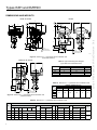
DIMENSIONS AND WEIGHTS
DN 25, 50, and 80
DN 100
E
E
C
I
H
K
Indicator cover
removal clearance
J
I
H
Indicator cover
removal clearance
K
C
C
A
B
G
A
B
F
G
B
D
25 mm
Mechanism box
removal clearance
D
A
G
25 mm
Mechanism box
removal clearance
F
25 mm
Mechanism box
removal clearance
F
R112a
Figure 5. Dimensions — Types EZH OS2 and EZHSO OS2
(Horizontal Position)
DN 25, 50, 80, and 100
E
I
Table 5. Approximate Regulator Weights
Types EZH OS2 and EZHSO OS2
H
J
WEIGHTS (kg)
DN
CL150/PN 16B
CL300/PN 25B/PN 40B
CL600
25
49
50
51
50
81
83
85
80
168
175
177
100
237
250
265
C
For Type EZHSO OS2 version add 1 kg
B
A
Table 6a. Dimensions — Types EZH OS2 and EZHSO OS2
D
DN
G
Diaphragm
25 mm
Mechanism box
removal clearance
F
R113a
OVERALL DIMENSIONS (mm)
F
G
Piston Bellows Diaphragm Piston
Bellows
25
50
181
80
Figure 6. Dimensions — Types EZH OS2 and EZHSO OS2
(Vertical Position)
204
223
162
71
74
100
Table 6b. Dimensions — Types EZH OS2 and EZHSO OS2
MAXIMUM OVERALL DIMENSIONS (mm)
A
DN
C
CL150 CL300 CL600 PN 16B PN 25B PN 40B
25
184
197
210
50
254
267
286
193.5
254
267
B
H
Type PRX Type PRX
Horizontal Vertical
D
E
J
Type PRX Type PRX
Horizontal Vertical
I
Type PRX Type PRX
Horizontal Vertical
250
290
310
315
320
260
250
113
280
190
265
320
320
330
380
310
310
144
270
190
270
80
298
317
337
310
317
301
400
400
366
500
390
390
200
100
352
368
394
350
368
345
442
427
410
580
394
394
240
270
140
K
38
51
R114a
6
Europe, Middle East, and Africa Document Only
D
Types EZH and EZHSO
E
K
Indicator cover
removal clearance
E
DN 25,
J
50,
I
and 80
H
K
Indicator cover
DN
removal clearance
E
Indicator cover
Indicator cover
removal clearance
K C removal clearance
100
E
E
K
I
J
I
H
J
I
K
H
C
H
(1)
I
Indicator cover
Indicator cover
removal clearance
K C
removal clearance
H
E
I
H
C
CB
C
B
A
A
B
B
A
A
R115a
A
A
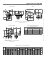
Figure 7. Dimensions — Types EZH and EZHSO
(Horizontal Position)
Table 7. Approximate Regulator Weights
Types EZH and EZHSO(1)
DN 25, 50, 80, and 100
E
I
H
WEIGHTS (kg)
DN
J
E
I
E
CL300/PN 25B/PN 40B
CL600
38
39
40
25
H
I
CL150/PN 16B
H
J
J
C
50
71
74
75
80
145
151
153
100
211
224
239
(1) For Type EZHSO version add 1 kg
R116a
C
C B
A
B
Figure 8. Dimensions — Types EZH and EZHSO
(Vertical Position)
B
A
A
Table 8. Dimensions — Types EZH and EZHSO
MAXIMUM OVERALL DIMENSIONS (mm)
A
DN
C
CL150 CL300 CL600 PN 16B PN 25B PN 40B
25
184
197
210
193.5
50
254
267
286
254
80
298
317
337
100
352
368
394
B
H
Type PRX Type PRX
Horizontal Vertical
E
J
Type PRX Type PRX
Horizontal Vertical
I
Type PRX Type PRX
Horizontal Vertical
62
290
310
320
260
250
113
280
190
267
83
320
320
380
310
310
144
270
190
310
317
105
400
400
500
390
390
200
270
270
350
368
137
442
427
580
394
394
240
140
K
38
51
R117a
7
Europe, Middle East, and Africa Document Only
B
B
Types EZH and EZHSO
UPPER
DIAPHRAGM
TYPE
PRX/120
TYPE
SA/2
FILTER
PILOT DISK
S
V
B
R
L
A
REGULATOR
DIAPHRAGM
LOWER
DIAPHRAGM
TYPE EZH
Inlet pressure (Pu)
Motorization pressure (Pm)
Pilot feeding pressure (Pup)
Outlet pressure (Pd)
Atmospheric pressure (Pb)
TYPE PRX:
S - BLEED PORT
B - SUPPLY PORT
L - MOTORIZATION PORT
A - SENSING PORT
TYPE SA/2
V - SENSING
R - PILOT
M - INLET
R98
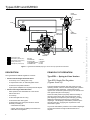
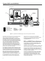
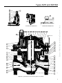
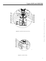
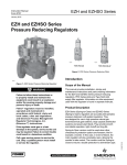
Figure 9. Type EZH DN 25/50/80 (Spring-to-Close Version) Operational Schematic
DESCRIPTION
PRINCIPLE OF OPERATION
The Types EZH and EZHSO regulators consist of:
Type EZH — Spring-to-Close Version
• Version without Integral Slam-Shut Valve:
-
An "E Body" or an "X Body plus a cap"
-
A compensation valve, an interchangeable orifice
-
An actuator with position indicator
- A pilot system adapted to the required pressure setpoint
• Version with Integral Slam-Shut Valve:
-
Same parts and sub-assemblies as in the version
without slam shut
-
An "X Body"
-
A valve with tight shut-off O-ring
-
An automatic slam-shut bypass
-
A release relay Type OS2 (see instruction manual
NTAOS2) consisting of:
· A mechanism box (BM)
· A safety manometric box (BMS) connected to the
outlet side of the regulator
8
Type EZH Single-Pilot Regulator
(Figures 9 and 10)
The pilot-operated Type EZH uses inlet pressure as the
operating medium, which is reduced through pilot operation
to load the actuator diaphragm. Outlet pressure (Pd)
opposes the motorization pressure (Pm) in the actuator and
also opposes the pilot control spring.
When the outlet pressure (Pd) drops below the setting of
the pilot control spring, pilot control spring force on the
pilot diaphragm thus opens the pilot valve plug, providing
additional motorization pressure (Pm) to the actuator
diaphragm. This diaphragm motorization pressure opens
the main valve plug, supplying the required flow to the
downstream system.
Any excess motorization pressure on the actuator diaphragm
escapes downstream through the bleed restriction in
the pilot.
Europe, Middle East, and Africa Document Only
M
Types EZH and EZHSO
V
R
S
M
B
L
A
RP
Europe, Middle East, and Africa Document Only
R2
IP
IS
Inlet pressure (Pu)
Motorization pressure (Pm)
Pilot feeding pressure (Pup)
Outlet pressure (Pd)
Atmospheric pressure (Pb)
TYPE PRX:
S - BLEED PORT
B - SUPPLY PORT
L - MOTORIZATION PORT
A - SENSING PORT
TYPE SA/2
V - SENSING
R - PILOT
M - INLET
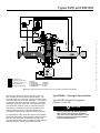
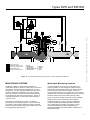
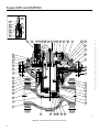
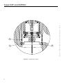
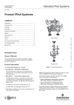
Figure 10. Type EZH-OS2 DN 100 (Spring-to-Close Version) Operational Schematic
When the gas demand in the downstream system has
been satisfied, the outlet pressure (Pd) increases. The
increased pressure is transmitted through the downstream
control line and acts on the pilot diaphragm. This pressure
exceeds the pilot spring setting and moves the Type PRX
diaphragm, closing the Type PRX orifice and interrupting
the motorization pressure supply to main valve actuator.
The excess of motorization pressure (Pm) acting on both
the main diaphragm and Type PRX pilot bleeds to the
downstream system through a bleed restriction in the pilot.
For Type EZH DN 100 a check valve (Figure 26) is installed
between outlet pressure and motorization pressure impulse
lines; this valve will protect the diaphragm assembly from
wrong procedures during startup, avoiding a too high pressure
differential between outlet and motorization pressure.
Type EZHSO — Spring-to-Open Version
Type EZHSO Single-Pilot Regulator
(Figures 11 and 12)
CAUTION
The pilot-operated Type EZHSO (Spring-toOpen version) will fail in open position in
case of main valve diaphragm failure or lack
of pressure supply to the pilot (see Table 4
for Failure Mode Analysis).
9
Types EZH and EZHSO
UPPER DIAPHRAGM
TYPE
PRX/120
FILTER
V
PILOT DISK
REGULATOR
DIAPHRAGM
TYPE
SA/2
S
B
R
L
A
R3
LOWER DIAPHRAGM
R2
R4
TYPE EZHSO
Inlet pressure (Pu)
Motorization pressure (Pm)
Pilot feeding pressure (Pup)
Outlet pressure (Pd)
Atmospheric pressure (Pb)
TYPE PRX:
S - BLEED PORT
B - SUPPLY PORT
L - MOTORIZATION PORT
A - SENSING PORT
TYPE SA/2
V - SENSING
R - PILOT
M - INLET
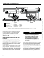
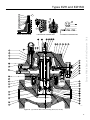
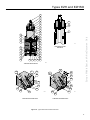
Figure 11. Type EZHSO DN 25/50/80 (Spring-to-Open Version) Operational Schematic
Type EZHSO uses inlet pressure as the operating medium,
which is reduced through pilot operation to load the
actuator diaphragm (lower chamber). The upper case of
Type EZHSO actuator is filled with pressure coming from
pre-regulator Type SA/2, which reduces inlet pressure (Pu)
to the constant value of outlet pressure plus approximately
3 bar. This pressure opposes the main spring force
that tends to open the regulator. Outlet or downstream
pressure (Pd) opposes the pilot control spring. When
outlet pressure drops below the setting of the pilot control
spring, pilot control spring force on the pilot diaphragm
opens the pilot valve plug, providing additional motorization
pressure (Pm) to the actuator diaphragm.
This diaphragm motorization pressure opens the main valve
plug, supplying the required flow to the downstream system.
Any excess motorization pressure on the actuator diaphragm
escapes downstream through the bleed restriction in the pilot.
When outlet pressure increases over the setting of the
pilot spring, the pilot valve plug will be closed reducing
motorization pressure to the actuator diaphragm; the
pressure in the upper case will force the regulator to close.
For Type EZHSO DN 100 a check valve (Figure 26) is
installed between outlet pressure and loading pressure
10
impulse lines; this valve will protect the diaphragm
assembly from wrong procedures during startup, avoiding
a too high pressure differential between outlet and
motorization pressure.
EZH and EZHSO Series Adjustment
The adjustment of the regulator is performed by means
of the pilot adjusting screw, which causes variation of the
compression of the control spring.
Adjustment is performed while the regulator is in operation with
the aid of a pressure gauge to monitor downstream pressure.
The shut-off valve downstream of the regulator must not be
completely closed, it is necessary that a small quantity of
gas flows downstream to allow the outlet side to vent when it
is necessary to lower the pressure.
Loosen the Type PRX pilot locknut and turn the adjusting
screw slowly clockwise to increase outlet pressure and
counterclockwise to decrease outlet pressure. Use a
pressure gauge to monitor the outlet pressure until the
desired pressure is reached. No adjustment is needed to
the Type SA/2 stabilizer filter.
Europe, Middle East, and Africa Document Only
M
Types EZH and EZHSO
V
R
S
M
B
L
A
Europe, Middle East, and Africa Document Only
R3
R4
R2
RP
Inlet pressure (Pu)
Motorization pressure (Pm)
Pilot feeding pressure (Pup)
Outlet pressure (Pd)
Atmospheric pressure (Pb)
TYPE PRX:
S - BLEED PORT
B - SUPPLY PORT
L - MOTORIZATION PORT
A - SENSING PORT
IP
TYPE SA/2
V - SENSING
R - PILOT
M - INLET
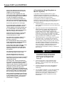
Figure 12. Type EZHSO DN 100 (Spring-to-Open Version) Operational Schematic
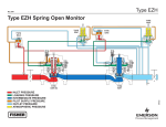
MONITORING SYSTEMS
Wide-Open Monitoring Systems
Monitoring regulation is overpressure protection by
containment, therefore, there is no relief valve to vent to the
atmosphere. When the working regulator fails to control
the pressure, a monitor regulator installed in series, which
has been sensing the downstream and control pressure,
goes into operation to maintain the downstream pressure
at a slightly higher level than normal pressure. During an
overpressure situation, the monitoring system keeps the
customer on line.
In normal operation of a wide-open configuration, the
working regulator controls the system’s outlet pressure.
With a higher outlet pressure setting, the monitor regulator
senses a pressure lower than its setpoint and tries to
increase outlet pressure by going wide open. If the working
regulator fails, the monitoring regulator assumes control and
holds the outlet pressure at its outlet pressure setting.
Also testing is relatively easy and safe. To perform a
periodic test on a monitoring regulator, increase the outlet
set pressure of the working regulator and watch the outlet
pressure to determine if the monitoring regulator takes over
at the appropriate outlet pressure.
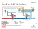
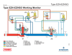
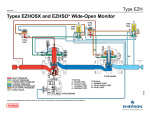
Figure 13 shows an upstream wide-open monitor Type EZH
(Spring-to-Close) and a downstream active regulator
Type EZHSO (Spring-to-Open). With this configuration,
in case of regulator main diaphragm failure, it will fail in
open position letting the monitor work properly; in case
of monitor main diaphragm failure, it will fail in close
position guaranteeing a protection against overpressure to
downstream system.
11
Types EZH and EZHSO
TYPE SA/2
V
TYPE PRX
TYPE PRX
S
R
S
R2
V
M
R
M
L
R1
B
B
L
A
A
TYPE SA/2
R4
TYPE EZH
Inlet pressure (Pu)
Motorization pressure (Pm)
Pilot feeding pressure (Pup)
Outlet pressure (Pd)
Atmospheric pressure (Pb)
TYPE PRX:
S - BLEED PORT
B - SUPPLY PORT
L - MOTORIZATION PORT
A - SENSING PORT
TYPE EZHO
TYPE SA/2
V - SENSING
R - PILOT
M - INLET
Figure 13. Upstream Wide-Open Monitoring System Operational Schematic for DN 25, 50, and 80
The schematic from Figure 13 represents the configuration
for the DN 25, 50, and 80, for the DN 100 the schematic
remains the same with the remark that a check valve
(Figure 26) must be installed between outlet pressure and
loading pressure impulse lines of the regulator and wide
open monitor as well.
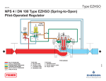
Working Monitor System with PRX Pilot
(Figure 14)
In a working monitoring system, the upstream regulator
requires two pilots and it is always the monitoring regulator.
The additional pilot PRX/125 or PRX/125-AP permits the
monitoring regulator to act as a series regulator to control an
intermediate pressure during normal operation. In this way,
both units are always operating and can be easily checked
for proper operation.
In normal operation, the working regulator controls the outlet
pressure of the system. The monitoring regulator’s working
pilot Type PRX/120 or PRX/120-AP controls the intermediate
pressure and the monitor pilot Type PRX/125 or PRX/125-AP
senses the system’s outlet pressure. If the working regulator
fails, the monitoring pilot Type PRX/125 or PRX/125-AP will
sense the increase in outlet pressure and take control.
12
CAUTION
The working regulator must be rated for the
maximum allowable operating pressure of the
system because this will be its inlet pressure
if the monitoring regulator fails. Also, the
outlet pressure rating of the monitoring
pilot Type PRX/125 or PRX/125-AP and any
other components that are exposed to the
intermediate pressure must be rated for full
inlet pressure.
Working monitor installations require a Type EZH or EZHSO
main valve with a Type PRX/120 or PRX/120-AP working
pilot, a Type PRX/125 or PRX/125-AP monitoring pilot for
the upstream regulator, and a Type EZH or EZHSO with
the appropriate Type PRX/120 or PRX/120-AP pilot for the
downstream regulator.
Adjusting the monitor regulator is the same as adjusting the
main regulator. Monitor setpoints are set slightly higher than
the main regulator. However, the value of this difference
cannot be determined in advance, as it depends on the
particular characteristics of each application.
Europe, Middle East, and Africa Document Only
R3
Types EZH and EZHSO
TYPE PRX/120
TYPE PRX/125
TYPE PRX/120
TYPE SA/2
R2
S
S
TYPE SA/2
B
B
L
L
V
R
S
M
A
V
B
L
R
R1
A
TYPE EZH
Inlet pressure (Pu)
Motorization pressure (Pm)
Pilot feeding pressure (Pup)
Outlet pressure (Pd)
Atmospheric pressure (Pb)
TYPE PRX:
S - BLEED PORT
B - SUPPLY PORT
L - MOTORIZATION PORT
A - SENSING PORT
TYPE EZH
R100
TYPE SA/2
V - SENSING
R - PILOT
M - INLET
Figure 14. Working Monitoring System Operational Schematic with Two EZH (Spring-to-Close) for DN 25, 50, and 80
The schematic from Figure 14 represents the configuration for
the DN 25, 50, and 80, for the DN 100 the schematic remains
the same with the remark that a check valve (Figure 26) must
be installed between outlet pressure and loading pressure
impulse lines of the regulator and working monitor as well.
INSTALLATION
!
WARNING
Personal injury or equipment damage, due
to bursting of pressure-containing parts may
result if this regulator is overpressured or
is installed where service conditions could
exceed the limits given in the characteristics
section and on the appropriate nameplate,
or where conditions exceed any rating of
the adjacent piping or piping connections.
To avoid such injury or damage, provide
pressure-relieving or pressure-limiting
devices to prevent service conditions
from exceeding those limits. Also, be sure
that installation is in compliance with all
applicable code and regulations.
Physical damage to the regulator can break
the pilot off the main valve, causing personal
injury and property damage due to bursting
of pressure-containing parts. To avoid such
injury and damage, install the regulator in a
safe location.
Only personnel qualified through training
and experience should install, operate, and
maintain a regulator.
Before installation, make sure that there is no
damage to, or debris in the regulator.
Make sure that all tubing and piping are clean
and unobstructed.
The regulator must be installed on
horizontal pipeline. For the version with
slam shut, the release relay must be
situated towards the bottom.
Installation according to EN 12186
is recommended.
When assembling with adjacent elements
take care not to create pressure force on
the body. The assembling elements (bolts,
O-rings, flanges) should be compatible with
the geometry and working conditions of the
equipment. If the case arises a support must
be used to avoid pressure force on the body
(a support can be installed under the flanges).
13
Europe, Middle East, and Africa Document Only
M
Connect the actuator to the impulse plug
keeping a minimum distance of 4 x D to a
straight run of the outlet pipe.
All Installations (Single Regulator or
Monitor Systems)
In the version with integrated slam shut
connect the safety manometric box (BMS) to
the outlet pipe keeping a minimum distance
of 4 x D to a straight run of the pipe.
A Type EZH or EZHSO regulator bleeds no gas to
atmosphere during normal operation, thus making the
regulator suitable for installation in pits and other enclosed
locations without elaborate venting systems.
In the case of functioning class B for the
slam shut it is necessary to regularly check
the safety manometric box (BMS) diaphragm.
This regulator can also be installed in pits subject to
flooding by venting the pilot spring case above the expected
flood level so that the pilot setting can be referenced to
atmospheric pressure.
Connect the reject tab to the outlet pipe.
It is recommended to separate the slam-shut
impulse from that of the actuator. Do not
connect impulses on the lower generator line.
It is recommended to install and isolation
tap and a vent tap. These can be useful for
slam-shut settings and verifications.
1.
Install the regulator so that the flow arrow on the main
valve matches the flow direction of process fluid through
the regulator.
2.
Apply pipe compound to the male pipeline threads
before installing a regulator with threaded NPT end
connections. Use gaskets between pipeline and
regulator flanges when installing a regulator with
flanged end connections. When installing buttweld end
connections, remove trim before welding and make
sure to use approved welding practices. Use approved
piping procedures when installing the regulator.
3.
Type PRX pilots have a 1/4-inch NPT vent connection
in the spring case. To remotely vent gas from the
spring case, remove the screened vent, and connect
1/4-inch piping or tubing to the spring case connection.
The piping or tubing should vent to a safe location,
have as few elbows as possible, and have a screened
vent on it’s exhaust. Install the regulator and any
remote vent piping or tubing so that the vent is
protected from condensation, freezing, or substances
that my clog it.
Check that the pilot impulse is connected
and in the case of an isolating tap (not
recommended) that it is open.
No modification should be made to the
structure of the equipment (drilling,
grinding, soldering...).
It is recommended to install a servicing valve
on the outlet pipeline to facilitate adjustments
and bleeding off to the atmosphere.
In the version with integral slam shut, verify
that the safety manometric box (BMS)
and spring correspond to the appropriate
operating conditions on the outlet side of
the regulator.
CAUTION
The equipment should not receive any type
of shock, especially the release relay.
To avoid freeze up due to pressure drop
and moisture in the gas, use anti-freeze
practices, such as heating the supply
gas or adding a de-icing agent to the
supply gas.
The user should verify or carry out a
protection adapted to the environment.
For DN 25 to 80, use long screws or threaded
stems when opening the actuator (warning
compressed spring).
The action of fire, seismic and lightening
are not taken into consideration in standard
regulators. If required, a special product
selection and/or specific calculations may be
supplied according to specific requirements.
A regulator may vent some gas to the
atmosphere. In hazardous or flammable gas
service, vented gas may accumulate, causing
personal injury, death, or property damage
due to bursting of pressure-retaining parts.
Vent a regulator in hazardous gas service to
a remote, safe location away from air intakes
or any hazardous location. The vent line or
stack opening must be protected against
condensation or clogging.
14
4.
Connect the actuator to the downstream sense
line on a straight run of outlet pipe 8/10 (inside
diameter). Connect the other end of that impulse to
the Type PRX port.
5.
Connect the PRX pilot port to the outlet pipeline at
a minimum distance of 4 x D from the regulator’s
outlet flange.
6.
For Type EZHSO installation, a vent valve downstream
of the regulator is needed. It should be installed
directly in the Type PRX pilot bleed line connection
(line from port "S" to pipe). A full bore NPS 1/4
ball valve for the vent line is preferred to provide
sufficient flow.
Europe, Middle East, and Africa Document Only
Types EZH and EZHSO
Types EZH and EZHSO
TYPE EZH OS2 SLAM-SHUT VERSION
Wide-Open Monitor Regulator
2.
In the case of opening the mechanism box lid:
Follow the procedures in the All Installations section,
and then continue with step 2 of this section. The
sense and bleed control lines of both the upstream and
downstream pilots will be connected to the downstream
piping (see Figure 13).
1.
After arming, never leave the key on the stem
2. Never put your fingers in or near the
reset mechanism area
Connect the pilot supply line for the downstream
regulator to the outlet "R" port of the Type SA/2 pilot
supply filter regulator.
Note
When using a Type SA/2 pilot supply filter
regulator, the differential pressure across the
regulator must be at least 3 bar for optimum
regulator performance. The Type SA/2 can
be removed if differential pressure across the
regulator is less than 3 bar and inlet pressure
stays at or below 13.8 bar.
Working Monitor Regulator
1.
Follow the procedure in the All Installations section, and
then continue with step 2 of this section. The sense line
of the upstream monitor pilot and the bleed and sense
lines of the downstream pilot will be connected to the
downstream piping (see Figure 14).
2.
Connect an inlet supply line from the upstream piping
to the inlet "M" port of the downstream Type SA/2 pilot
supply filter regulator.
Startup
3.
Connect a control (sense) line from the "A" port of the
upstream working Type PRX pilot to the intermediate
pressure portion of piping, using 8/10 (inside diameter) tube.
1.
Make sure all block valves, vent valves, and control line
valve(s) are closed.
4.
Connect a downstream bleed line from the "S"
port of the upstream working Type PRX pilot to the
intermediate pressure portion of piping, using 8/10
(inside diameter) tube.
2.
Back out the pilot adjusting screw(s).
3.
Slowly open the valves in the following order:
Type EZH Startup:
- Inlet block valves.
- Pilot supply and control line valve(s), if used.
STARTUP AND ADJUSTMENT
4.
Crack open the outlet block valve or bypass valve to
allow minimum flow.
Pre-startup Considerations
5.
After adjusting the Type PRX pilot(s) to the desired
pressure setting(s), slowly open the downstream block
valve wide open.
6.
Close the bypass valve, if used.
Each regulator is factory-set for the outlet pressure specified
on the order. If no setting was specified, outlet pressure
was factory-set at the mid-range of the pilot control spring.
Before beginning the start-up procedure in this section make
sure the following conditions are in effect:
• Block valves isolate the regulator
• Vent vales are closed
• A bypass, if any, is in operation.
In all cases, check the control spring setting to make sure it
is correct for the application.
CAUTION
Be sure to slowly introduce pressure into the
system to prevent downstream overpressure
due to potential rapid pressure increase.
Pressure gauges should always be used to
monitor downstream pressure during startup.
Procedures used in putting this regulator
into operation must be planned accordingly
if the downstream system is pressurized by
another regulator or by a manual bypass.
Type EZHSO Startup:
1.
Make sure all block valves, except valve R4, vent
valves, and control line valve(s) are closed.
2.
Back out the pilot adjusting screw(s).
3.
Introduce upstream pressure by slowly opening inlet valve.
4.
Slowly open valve R2.
5.
Open valve R3.
6.
Close valve R4, the regulator Type EZHSO close.
7.
Open valve R4.
8.
Close valve R3.
9.
Slowly open downstream valve, making sure that
there is a constant sufficient pressure drop across the
regulator. If downstream pressure climbs too close to
upstream pressure, the regulator will again fully open.
In this case, start-up procedure needs to be repeated.
15
Europe, Middle East, and Africa Document Only
1.
Types EZH and EZHSO
For a wide-open downstream monitor installation, adjust
the upstream working pilot until intermediate pressure is
higher than the desired setpoint of the monitor pilot. Adjust
the downstream monitoring pilot to the desired monitoring
takeover pressure. Reduce the upstream pilot to the normal
outlet pressure setting.
For a wide-open upstream monitor installation, adjust
the downstream working pilot to a setpoint higher than
the setpoint of the monitor pilot. Adjust the upstream
monitoring pilot to the desired monitoring takeover
pressure. Reduce the downstream pilot to the normal
outlet pressure setting.
For a working monitor installation, adjust the setpoint
of the upstream monitor pilot to the desired maximum
pressure. Adjust the upstream working pilot to the desired
intermediate pressure setting. Adjust the downstream
pilot to a pressure setting slightly above the upstream
monitor pilot pressure setting. Adjust the upstream
monitor pilot to its desired setpoint. Establish final desired
downstream pressure by adjusting the downstream working
regulator pilot.
Type PRX Pilot Adjustment
To adjust a standard Type PRX pilot, loosen the locknut, and
turn the adjusting screw.
Turning the adjusting screw clockwise into the spring case
increases the spring compression and pressure setting.
Turning the adjusting screw counter clockwise decreases the
spring compression and pressure setting
When the required pressure setting is maintained for several
minutes, tighten the locknut to lock the adjusting screw
in position.
Type PRX Pilot Restrictor and Damper
Screw Adjustment
Note
Recommended initial setting of the restrictor
screw is turned completely in (clockwise)
and then turned out 1/2 turn. The damper
screw initial setting is turned completely out
(counter clockwise).
The Type PRX/125 (upstream monitor pilot in
working monitor installations) does not have
a restrictor screw.
10. After adjusting the Type PRX pilot(s) to the desired
pressure setting(s), slowly open the downstream block
valve wide open.
The restrictor screw of the Type PRX pilot can be used if there
is hunting of the set pressure. Slowly turning out the restrictor
screw (counterclockwise) will help steady the set pressure.
11. Close the bypass valve, if used.
Type OS2 Manometric Box Set Point
Verification Procedure
Turning out the restrictor screw will slightly decrease set
pressure, so adjustment of the pilot adjusting screw may
be necessary.
Using the vent valve supply a pressure equal to the set
pressure foreseen for the regulator.
-
The damper screw can be turned in (clockwise) to slow the
response of the regulator. It is advisable that adjustment of
the damper and restrictor screws be limited to 1/4 turn at a
time to observe the response of the regulator(s).
1st release relay stage
à Set (Stage 1)
-
Slam-shut valve plug
SHUTDOWN
à Open (Stages 2 and 3)
à Progressively increase the pressure until tripping occurs
CAUTION
à Adjust setting if necessary (NTAOS2). Note the
set point value on the equipment or mark it on a
commissioning document
If the pilot bleed control line pressure is shut
down first, the downstream system may be
subjected to full inlet pressure (Pu).
1.
If the pilot setting must be disturbed, be sure to keep
some tension on the spring. This will prevent trapping
inlet pressure during blow down.
2.
Slowly close the valves in the following order:
- Inlet block valve,
R121
TRIGGERED POSITION
STAGE 1
STAGES 2 AND 3
- Outlet block valve,
- Control line valve(s), if used.
Figure 15. Setpoint Verification Phase
16
3.
Open the vent valves to depressurize the system.
Europe, Middle East, and Africa Document Only
For a single regulator, set the pilot to the desired outlet
(control) pressure according to the Pilot Adjustment procedure.
6.
The regulator parts are subject to normal wear and must be
inspected periodically and replaced as necessary.
Set the seat ring (key 2) back in the body (key 1) with
the curved side down and the seat edge up. To check
O-ring (key 7), skip to the Intermediate Flange O-ring
Maintenance section. Place the cage (key 3) on top of
seat ring. The cage will engage the step on the seat ring.
7.
The frequency of inspection and replacement depends on
the severity of service conditions and on applicable codes
and regulations.
Place the disk holder assembly (key 30) and disk
retainer (key 31) on the sleeve adaptor (key 27).
8.
Use silicone grease for O-rings and diaphragm, molybdenum
graphite grease for spring and mechanical parts.
Insert the spring lock washers (key 32) and hex
socket cap screws (key 33) and tighten. See Torque
Specification table for proper torque.
9.
Carefully lift the upper actuator casing and lower
actuator casing assembly (keys 11 and 5) and place on
the body (key 1). Secure the screws (key 24).
See Torque Specification table for proper torque.
MAINTENANCE
For both Types EZH and EZHSO DN 100, never remove or
disconnect the check valve installed between the two casings.
!
WARNING
To avoid personal injury or property
damage from sudden release of pressure,
isolate the regulator from the pressure
system, and release all pressure from the
pilot and main valve before performing
maintenance operations.
CAUTION
Use proper lifting techniques, when lifting
the upper and lower actuator casings
(keys 11 and 5, Figure 16) off the body
(key 1, Figure 16).
Type EZHSO Disk Maintenance
1.
Remove screws (key 24).
2.
Carefully lift the upper actuator casing and lower
actuator casing assembly (keys 11 and 5) off the body
(key 1).
3.
Remove the hex socket cap screw (key 154). Lift off the
disk holder assembly (key 30).
4.
Remove the O-ring (key 29). Inspect the O-ring for
damage or wear, and replace if necessary. Lightly
lubricate O-ring before placing in the sleeve adaptor
(key 27).
5.
Remove the cage (key 3), seat ring (key 2) and O-ring
(key 34). Inspect the O-ring for damage or wear, and
replace if necessary. Lightly lubricate O-ring before
placing in the body (key 1). Do not attempt to remove
the sleeve adaptor.
6.
Set the seat ring (key 2) back in the body (key 1) with
the curved side down and the seat edge up. To check
O-ring (key 7), skip to the Intermediate Flange O-ring
Maintenance section. Place the cage (key 3) on top of
seat ring. The cage will engage the step on the seat ring.
7.
Place the disk holder assembly (key 30) on the sleeve
adaptor (key 27).
8.
Insert the hex socket cap screw (key 154) and tighten.
See Torque Specification table for proper torque.
9.
Carefully lift the upper actuator casing and lower
actuator casing assembly (keys 11 and 5) and place on
the body (key 1). Secure the screws (key 24).
See Torque Specification table for proper torque.
The actuator assembly weighs more than 45 kg.
Main Valve and Actuator Maintenance
Disk Maintenance DN 25, 50, and 80
(Figure 16)
Type EZH Disk Maintenance
1.
Remove screws (key 24).
2.
Carefully lift the upper actuator casing and lower
actuator casing assembly (keys 11 and 5) off the body
(key 1).
3.
Remove the hex socket cap screws (key 33) and spring
lock washers (key 32). Lift off the disk holder assembly
(key 30) and disk retainer (key 31).
4.
Remove the O-ring (key 29). Inspect the O-ring for
damage or wear, and replace if necessary. Lightly
lubricate O-ring before placing in the sleeve adaptor
(key 27).
5.
Remove the cage (key 3), seat ring (key 2) and O-ring
(key 34). Inspect the O-ring for damage or wear, and
replace if necessary. Lightly lubricate O-ring before
placing in the body (key 1).
Disk Maintenance Type EZH DN 100
(Figure 17)
1.
Remove screws (key 77).
2.
Carefully lift the cap (key 70) off the upper casing
(key 11) and unscrew the eye bolts (key 35) from the
cap (key 70).
17
Europe, Middle East, and Africa Document Only
Types EZH and EZHSO
3.
Remove the O-ring (key 75). Inspect for damage or
wear, and replace if necessary.
Disk Maintenance Type EZHSO DN 100
(Figure 19)
4.
Remove the O-ring (key 69). Inspect for damage or
wear, and replace if necessary. Lightly lubricate O-ring
before placing inside cap (key 70).
1.
Remove cap screws (key 77).
2.
5.
Remove smart screws (key 68) from sleeve.
Carefully lift the cap (key 70) off of the upper casing
(key 11).
6.
Fit eye bolt (key 35) into ring nut (key 73) threaded hole.
3.
7.
Carefully remove the trim system from the sleeve guide
utilizing the eye bolt (key 35).
Remove O-ring (key 75). Inspect the O-ring for damage
or wear, and replace if necessary.
4.
8.
Remove the hex socket cap screws (key 33) and lock
washers (key 32).
Remove O-ring (key 69). Inspect the O-ring for damage
or wear, and replace if necessary. Lubricate O-ring
before placing inside cap.
9.
Lift off the disk retainer (key 31) and disk assembly
(key 30). Inspect for damage or wear, and replace
if necessary.
5.
Remove special screws (key 68) from sleeve.
6.
Carefully remove the trim system from the sleeve guide
utilizing the eye bolt (key 35) or stem nut.
7.
Remove socket head cap screws (key 154).
8.
Lift off the disk holder assembly (key 30).
9.
Remove the O-ring (key 29). Inspect the O-ring for
damage or wear, and replace if necessary. Lightly
lubricate O-ring before placing in the sleeve adaptor
(key 27).
10. Remove the O-ring (key 29). Inspect the O-ring for
damage or wear, and replace if necessary.
11. Place disk assembly (key 30) onto disk retainer (key 31).
12. Place disk retainer assembly into sleeve adapter
(key 27) and align screw holes.
13. Place lock washer (key 32) on screws (key 33).
14. Screw together the disk retainer assembly into the
sleeve adapter assembly. See Torque Specification
table for proper torque.
15. Lubricate the sleeve (key 14).
16. Carefully insert the trim system into the sleeve guide
(key 61) utilizing eye bolt (key 35). Align sleeve utilizing
the socket head cap screw (key 74) as a guide.
17. Screw smart screws (key 68) to affix the sleeve system.
See Torque Specification table for proper torque.
18. Remove eye bolt (key 35) from ring nut (key 73)
threaded hole.
19. Carefully place the cap on the upper casing (key 11).
20. Lubricate cap screws (key 77) and attach cap (key 70)
to the upper casing using cap screws (key 77).
See Torque Specification table for proper torque.
Note
Rotate the cap such that the outer holes for
sensing lines are in line with upper casing
holes for sensing lines: to validate the
alignment and before attaching cap, check
that travel indicator is aligned on the cap and
on the upper casing.
21. Mount O-ring (key 75) on the cap.
22. Screw the eye bolts (key 35) on the cap (key 70).
18
10. Place disk holder assembly (key 30) into sleeve adaptor
(key 27) and align screw holes.
11. Place on screws (key 154). Screw together the disk
holder assembly into the sleeve adaptor assembly.
See Torque Specification table for proper torque.
12. Lubricate the sleeve (key 14).
13. Carefully insert the trim system into the sleeve guide
(key 61). Align sleeve utilizing the socket hex cap screw
(key 74) as a guide.
14. Screw smart screws (key 68) to affix the sleeve system.
See Torque Specification table for proper torque.
15. Place O-ring (key 69) on the cap (key 70).
16. Carefully place the cap on the upper actuator casing
(key 11).
17. Lubricate cap screws (key 77) and attach cap (key 70)
to the upper casing using cap screws (key 77).
See Torque Specification table for proper torque.
Note
Rotate the cap such that the outer holes for
sensing lines are in line with upper casing
holes for sensing lines: to validate the
alignment and before attaching cap, check
that travel indicator is aligned on the cap and
on the upper casing.
18. Mount O-ring (key 75) on the cap.
Europe, Middle East, and Africa Document Only
Types EZH and EZHSO
Types EZH and EZHSO
Intermediate Flange O-ring Maintenance for
Types EZH and EZHSO (DN 25, 50, and 80)
Remove screws (key 24).
2.
Carefully lift the upper and lower actuator casing
assembly (keys 11 and 5) off the body (key 1).
3.
Remove cap screws (key 6).
4.
Lift off intermediate flange (key 25).
5.
Remove O-ring (key 7). Inspect the O-ring for damage
or wear, and replace if necessary. Lightly lubricate
O-ring before placing in the body (key 1).
6.
Place the intermediate flange (key 25) on the body, make
sure to position the screws (key 24) holes on the outside
of the body (key 1). Secure with cap screws (key 6).
See Torque Specification table for proper torque.
7.
Continue with "Disk Maintenance" section, step 7.
Actuator Assembly Maintenance
DN 25, 50, and 80
Type EZH Actuator Maintenance
1.
Make a mark on the upper actuator casing (key 11)
lower actuator casing (key 5), intermediate flange
(key 25) and body (key 1) to indicate proper alignment.
2.
Remove travel indicator assembly (keys 138, 139, 140,
141, 142, 143, 144, 145, and 192), by loosening the
travel indicator fitting (key 141) and lifting out the travel
indicator assembly.
3.
Replace the two opposite bolts (keys 21, 22, and 23) with
the two threaded stems and nuts delivered with the unit.
CAUTION
Secure the removal of the casings (keys 11 and
5) by finishing with these two threaded stems.
4.
Remove screws, washers and hex nuts (keys 21, 22,
and 23). Remove all the screws first, then the two
threaded stems and bracket. Take care to balance the
upper actuator casing while removing the spring tension.
Carefully lift the upper actuator casing (key 11) off the
lower actuator casing (key 5).
5.
Remove spring (key 13).
6.
Remove screws (key 16). Lift off diaphragm (key 20)
and the inlet plate (key 18). Remove O-rings (keys 15
and 17). Inspect the diaphragm and O-rings for damage
or wear, and replace if necessary.
7.
Inspect the upper actuator casing (key 11), O-ring (key 9),
anti-friction split rings (key 8), and anti-friction ring (key 4)
for damage or wear. If damaged, remove the O-rings and
split rings; replace with new parts. Lightly lubricate the
8.
Remove screws (key 24). Lift off the lower actuator
casing (key 5). Remove screws (key 33) and spring
lock washers (key 32). Lift off the disk holder assembly
(key 30) and disk retainer (key 31).
9.
Slide the sleeve (key 14) out of the lower actuator
casing (key 5) and slide the outlet plate (key 19) off the
sleeve. Check the sleeve for scratches, burrs, or other
damage and replace if necessary.
10. Remove the sleeve adaptor (key 27) from the sleeve
(key 14). Take care not to damage the sleeve while
removing the sleeve adaptor. Check the O-ring (key 28)
for damage, and replace if necessary.
11. Place the sleeve adaptor on the sleeve and tighten.
12. Inspect the lower actuator casing (key 5), O-ring (key 9),
anti-friction split rings (key 8), and anti-friction ring
(key 4) for damage or wear. If damaged, remove the
O-ring and split rings; replace with new parts. Lightly
lubricate the O-ring and split rings. Place the split rings
in the body first, then slide the O-ring between the
split rings.
13. Slide the outlet plate (key 19) onto the sleeve (key 14)
and slide the sleeve into the lower actuator casing
(key 5). Place the disk holder (key 30) and disk retainer
(key 31) on the sleeve adaptor (key 27). Insert the spring
lock washers (key 32) and screws (key 33) and tighten.
See Torque Specification table for proper torque.
14. Lightly lubricate the O-rings (keys 15 and 17) and the
inner and outer diaphragm (key 20) edges. Place the
inlet plate (key 18) and the diaphragm (key 20) on the
sleeve (key 14). Make sure O-rings (key 15 and 17) are
correctly positioned. Insert and tighten the hex socket
cap screws (key 16). See Torque Specification table for
proper torque.
15. Carefully lift the lower actuator casing assembly (key 5)
and place on the body (key 1). Take care to match up
the alignment marks. Secure with screws (key 24).
See Torque Specification table for proper torque.
16. Lightly lubricate the spring (key 13) and place on the
inlet plate (key 18).
17. Carefully place the upper actuator casing (key 11)
on the lower actuator casing (key 5). Take care to
match up the alignment marks. Insert the two threaded
stems 180° apart and away from flanges. Place the
washers and hex nuts (keys 22 and 23) and brackets
on the long cap screws and evenly tighten. Install
remaining small cap screws (key 21), washers, and
hex nuts. Replace the two threaded stems by two bolts
(keys 21, 22, and 23). See Torque Specification table
for proper torque.
18. Place the travel indicator assembly (keys, 138, 139,
140, 141, 142, 143, 144, 145, and 192) in the upper
actuator casing (key 11) by hitting the tip of the stem
(key 139) to clip the fitting (key 144) into the plate
(key 18) and tighten the travel indicator fitting (key 141).
19
Europe, Middle East, and Africa Document Only
1.
O-ring and split rings. Place the split rings in the body
first, then slide the O-ring between the split rings.
Types EZH and EZHSO
sleeve (key 14). Make sure O-rings (keys 15 and 17)
are correctly positioned. Insert and tighten the hex
socket cap screws (key 16). See Torque Specification
table for proper torque.
Type EZHSO Actuator Maintenance
Make a mark on the upper actuator casing (key 11),
lower actuator casing (key 5), intermediate flange
(key 25), and body (key 1) to indicate proper alignment.
2.
Remove travel indicator assembly (keys 138, 139,
140, 141, 142, 143, 144, 145, and 192), if present, by
loosening the travel indicator fitting (key 141) and lifting
out the travel indicator assembly.
3.
Remove protective cap (key 146). Loosen and remove
hex nuts (key 151).
4.
Remove cap screws (key 21), washers (key 22), and
hex nuts (key 23). Remove protective cap (key 146)
and remove hex nuts (key 151). Carefully lift the upper
actuator casing (key 11) off the lower actuator casing
(key 5).
5.
Remove the socket head cap screws (key 16). Lift off
the diaphragm (key 20) and the inlet plate (key 18).
Remove O-rings (keys 15 and 17). Inspect the
diaphragm and O-rings for damage or wear, and
replace if necessary.
6.
Inspect the upper actuator casing (key 11), O-ring
(key 9), anti-friction split rings (key 8), and anti-friction
ring (key 4) for damage or wear. If damaged, remove
the O-ring and split rings, and replace with new parts.
Lightly lubricate the O-ring and split rings. Place the
split rings in the body first, then slide the O-ring between
the split rings.
7.
Remove screws (key 24). Lift off the lower actuator
casing (key 5). Remove the hex socket cap screw
(key 154). Lift off the disk holder assembly (key 30).
8.
Slide the sleeve (key 14) out of the lower actuator
casing (key 5) and slide the outlet plate (key 19) off of
the sleeve. Check the sleeve for scratches, burrs, or
other damage, and replace if necessary.
9.
Inspect the lower actuator casing (key 5), O-ring
(key 9), anti-friction split rings (key 8), and anti-friction
ring (key 4) for damage or wear. If damaged, remove
the O-ring and split rings, and replace with new parts.
Lightly lubricate the O-ring and split rings. Place the
split rings in the body first, then slide the O-ring between
the split rings.
10. Slide the outlet plate (key 19) onto the sleeve
(key 14) and slide the sleeve into the lower actuator
casing (key 5). Place the disk holder assembly
(key 30) on the sleeve adaptor (key 27). Insert the hex
socket cap screw (key 154) and tighten. See Torque
Specification able for proper torque.
11. Lightly lubricate the O-rings (keys 15 and 17) and the
inner and outer diaphragm (key 20) edges. Place the
inlet plate (key 18) and the diaphragm (key 20) on the
20
12. Carefully lift the lower actuator casing assembly (key 5)
and place on the body (key 1). Make sure to match up
the alignment marks. Secure with screws (key 24).
See Torque Specification table for proper torque.
13. Carefully place the upper actuator casing (key 11) on
the lower actuator casing (key 5). Make sure to match
up the alignment marks. Insert the two long bolts 180°
apart and away from flanges. Place the washers
(key 22), hex nuts (key 23), and brackets (key 35) on
the long bolts and evenly tighten. Using proper bolting
techniques, install remaining short cap screws (key 21),
washers, and hex nuts. See Torque Specification table
for proper torque.
14. Tighten hex nuts (key 151), install protective cap
(key 146).
15. Place travel indicator assembly (keys 138, 139, 140,
141, 142, 143, 144, 145, and 192) in the upper actuator
casing (key 11), if present, and tighten the travel
indicator fitting (key 141).
Type EZH DN 100 Actuator Assembly
Maintenance (Figure 17)
1.
Remove travel indicator assembly (keys 71, 138, 139,
140, 141, 142, 143, 144, 145, and 192), if present, by
loosening the travel indicator fitting (key 141) and lifting
out the travel indicator assembly.
2.
Remove hex head cap screws (key 21), washers
(key 22), and hex nuts (key 23). Carefully lift the
upper actuator casing (key 11) off the lower actuator
casing (key 5). Inspect the upper actuator casing
(key 11), O-rings (key 9) and anti-friction rings
(key 8) for damage or wear. If damaged, remove and
replace with new parts. Place the anti-friction rings
in the body first, then slide the O-ring between the
anti-friction rings.
3.
Lift off the diaphragm/plates system. Remove O-ring
(key 15). Inspect diaphragm and O-rings for damage or
wear, and replace if necessary.
4.
Remove sleeve guide (key 61) utilizing cap (key 70)
to unscrew.
5.
Remove cage (key 78).
6.
Remove seat ring (key 2). Inspect seat ring for damage
or wear. If damaged, replace with new parts.
7.
Remove O-ring (key 34) from body. Inspect for damage
or wear. If damaged, replace with new parts.
Europe, Middle East, and Africa Document Only
1.
Types EZH and EZHSO
Lubricate O-ring (key 34) and replace into the body.
9.
Place seat ring (key 2) on top of O-ring in body.
10. Place cage (key 78) on the top of seat ring (key 2).
Type EZHSO DN 100 Actuator Assembly
Maintenance (Figure 19)
1.
Remove closing cap (key 146), unscrew 2 nuts
(key 151). If present, remove travel indicator assembly
by unscrewing the travel indicator fitting (key 141), then
pull out the stem (key 139).
2.
Remove hex head cap screws (key 21), washers
(key 22), and hex nuts (key 23). Carefully lift the
upper actuator casing (key 11) off the lower actuator
casing (key 5). Inspect the upper actuator casing
(key 11), O-rings (key 158) and anti-friction rings
(key 157) for damage or wear. If damaged, remove
and replace with new parts. Place the anti-friction rings
in the cap first, then slide the O-ring between the
anti-friction rings.
3.
Unscrew 8 smart screws (key 68). Lift up and remove
the sleeve assembly (key 14). Lift off the diaphragm/
plates system. Remove O-ring (key 15) and replace
as needed. Inspect diaphragm (key 20) for damage
or wear, remove screws (key 16), lift off inlet plate
(key 18) to replace diaphragm and O-ring (key 17)
if necessary.
4.
Unscrew 8 screws (key 77) to remove cap (key 70) from
the upper casing (key 5). Align screw holes on the cap
(key 70) to the sleeve guide screw (key 66). Remove
sleeve guide (key 61) utilizing cap (key 70) to unscrew.
Inspect O-rings (key 8), (key 64) and (key 153) for
damage or wear, replace anti-friction ring (key 9) and
O-ring (key 8) if necessary. Unscrew 8 bolts (key 6) and
remove washer (key 67). Lift off lower casing (key 5).
Inspect O-rings (key 7) and (key 63) for damage or
wear, replace them if necessary.
5.
Remove cage (key 78).
6.
20. Lubricate and mount the O-ring (key 69) on the cap
(key 70).
Remove seat ring (key 2). Inspect seat ring for damage
or wear. If damaged, replace with new parts.
7.
21. Lubricate and mount O-rings (key 9) and anti-friction
rings (key 8) inside the cap (key 70).
Remove O-ring (key 34) from body. Inspect for damage
or wear. If damaged, replace with new parts.
8.
Lubricate O-ring (key 34) and replace into the body.
22. Carefully place the cap on the upper casing (key 11).
9.
Place seat ring (key 2) on top of O-ring in body.
23. Lubricate cap screws (key 77) and attach cap (key 70)
to the upper casing using cap screws (key 77). See
Torque Specification table for proper torque.
10. Place cage (key 78) on the top of seat ring (key 2).
11. Screw sleeve guide into lower casing (key 5) utilizing
cap (key 70).
12. Lubricate the sleeve (key 14) in the upper plate contact
area and assemble the diaphragm/plates system on the
sleeve system.
13. Screw the smart screws (key 68) — already on the
sleeve — to fix the diaphragm/plates system on the
sleeve system. See Torque Specification table for
proper torque.
14. Lubricate lower casing (key 5) on the diaphragm
contact area.
15. Carefully insert the trim system into the sleeve guide
(already assembled on the body) utilizing the eye-bolt
(key 35) that fits in the ring nut (key 73) threaded hole.
16. Lubricate the diaphragm (key 20) on the upper casing
contact area.
17. Carefully place the top actuator casing on the top of the
lower actuator casing/trim system using a stud to guide.
Note
Rotate the upper casing such that the outer
holes for sensing lines are perpendicular to
gas flow.
18. Lubricate threads on bolts (key 21).
19. Bolt together the upper and lower actuator casings using
bolts (key 21), washers (key 22), and nuts (key 23).
See Torque Specification table for proper torque.
24. Mount O-ring (key 75) on the cap (key 70).
25. Screw the eye-bolts (key 35) on the cap (key 70).
26. Place travel indicator assembly (keys 138, 139, 140,
141, 142, 143, 144, 145, and 192) in the upper actuator
casing (key 11), if present, and tighten the travel
indicator fitting (key 141).
11. Place lower casing (key 5) on top of body. Replace
washer (key 67) and tighten bolts (key 6). Screw
sleeve guide into lower casing (key 5) utilizing cap
(key 70).
12. Lubricate the sleeve (key 14) in the upper plate contact
area and assemble the diaphragm/plates system on the
sleeve system. Tighten screws (key 16) using a "star"
criss-cross pattern for five times until proper specified
torque is achieved.
21
Europe, Middle East, and Africa Document Only
8.
Types EZH and EZHSO
13. Screw the smart screws (key 68) — already on the
sleeve — to fix the diaphragm/plates system on
the sleeve system. See Torque Specification table
for proper torque. Tighten screws (key 68) using a
"star" criss-cross pattern until proper specified torque
is achieved.
5.
Remove mechanism box.
6.
Unscrew screws (key 50) from the connecting part
(key 48).
7.
Remove connecting part (key 48), O-rings (keys 56 and
49) and if necessary the two guide rings (rep. 54).
14. Lubricate lower casing (key 5) on the diaphragm
contact area.
8.
Remove spring (key 55) and valve plug (key 46).
9.
Unscrew bypass (key 53) and remove valve O-ring.
16. Lubricate the diaphragm (key 20) on the upper casing
contact area.
17. Lubricate and mount the O-ring (key 69) on the cap
(key 70). Lubricate and mount O-rings (key 9) and antifriction rings (key 8) inside the cap (key 70). Carefully
place the cap on the actuator upper casing (key 11).
Align the travel indicator hole on the cap (key 70) to the
upper casing travel indicator hole. Screw 8 screws
(key 77) to tighten cap (key 70) to the upper casing
(key 5). Carefully place the top actuator casing on the
top of the lower actuator casing/trim system using a stud
to guide.
10. Removing the seat (key 52) (not recommended) from
the body (key 47) requires a special extraction tool.
Type PRX Pilot Maintenance (Figure 23)
CAUTION
Always remove spring (key 7) tension before
performing maintenance on this unit.
To remove spring tension loosen locknut
(key 2) and backout adjusting screw
(key 1) until compression is removed from
the spring.
Note
Rotate the upper casing such that the outer
holes for sensing lines are perpendicular to
gas flow.
Lower Case Maintenance
1.
Disconnect pilot and remove it from the line.
2.
Remove screws (key 10) from lower cover (key 21) and
the separate lower cover from the body (key 16).
3.
Use a wrench to hold the stem (key 23) and break
loose the stem nut (key 20). Remove the stem nut and
washer (key 11).
4.
20. Assemble one nut (key 151) to the stem (key 147) until
achieve specified torque, and then assemble another nut
(key 151) to lock position of stem. Screw on the closing
cap (key 146). Mount O-ring (key 75) on the cap (key 70).
Remove the diaphragm plate (key 13), diaphragm
(key 14), pad holder (key 22) and O-ring (key 18).
Inspect parts for damage or wear, replace if necessary.
5.
21. If present, set the stem (key 139) through the casing
hole and tap it into the groove in the diaphragm plate
(key 18). Slide the travel indicator fitting (key 141) over
the stem and tighten to the cap (key 70).
Remove orifice (key 19) and O-ring (key 17). Inspect
the parts for damage or wear, and replace if necessary.
Lightly lubricate the O-ring and place in the body
(key 16). Install the orifice.
6.
Set the pad holder (key 22) in the body (key 16).
7.
Lightly lubricate the rims of the diaphragm (key 14)
and place it on top of the pad holder (key 22). Set the
diaphragm plate (key 13) on the diaphragm (key 14).
8.
Lightly lubricate the O-ring (key 18) and place it in the
lower case (key 21).
9.
Place the washer (key 11) and stem nut (key 20) on the
stem (key 23) and tighten.
If also performing upper case maintenance, skip to
step 2 of "Upper Case Maintenance" section.
18. Lubricate threads on bolts (key 21).
19. Bolt together the upper and lower actuator casings using
bolts (key 21), washers (key 22), and nuts (key 23).
See Torque Specification table for proper torque. Tighten
screws (key 16) using a "star" criss-cross pattern for
five times until proper specified torque is achieved.
Type EZH OS2 Regulator with Slam-shut
Maintenance (Figure 20)
1.
Unscrew the BMS (safety manometric box) impulse
line connector.
2.
Remove cover (key 57) from the mechanism box (BM).
3.
Unscrew fastening screw (key 51).
4.
Remove holding pin.
22
10. Insert screws (key 10) in the lower cover (key 21) and
tighten uniformly to ensure proper seal.
Europe, Middle East, and Africa Document Only
15. Carefully insert the trim system into the sleeve guide
(key 61).
Types EZH and EZHSO
Upper Case Maintenance
Disconnect pilot and remove it from the line.
2.
Loosen locknut (key 2) and backout adjusting screw
(key 1) until compression is removed from the spring.
Remove cap (key 3).
3.
4.
5.
6.
Lift the spring carrier (key 6) the spring (key 7) and
O-ring (key 4) out of the upper cover (key 8). Inspect
the O-ring and replace if necessary.
Remove screws (key 10) from lower cover (key 21) and
separate lower cover from the body (key 16), unless
removed during lower diaphragm maintenance. Use a
wrench to hold stem (key 19) securely while removing
the stem nut (key 26).
Remove remaining loose components: washer, upper
diaphragm plate, diaphragm, lower diaphragm plate
and O-rings (keys 11, 13, 14, 15, 18, and 25). Inspect
diaphragm and O-rings for damage or wear, and replace
if necessary.
Lightly lubricate the O-ring (key 25). Place the O-ring
over the stem (key 19) and press it down into the body
(key 16).
7.
Set the lower diaphragm plate (key 15) into the body
(key 16).
8.
Lightly lubricate the rims of the diaphragm (key 14)
and place it in the body (key 16) on top of the lower
diaphragm plate (key 15).
9.
Set the upper diaphragm plate (key 13) on top of the
diaphragm (key 14).
When using a Type PRX/120 pilot with
a Type PRX/125 pilot as monitor, follow
these steps:
5.
Damper and Restrictor Maintenance
1.
Remove the screw (key 31) and plate (key 29).
2.
Remove bolts (key 30).
3.
Remove the damper adjusting screw (key 27). Remove
and inspect O-ring (key 28) for damage or wear, and
replace if necessary. Lightly lubricate O-ring before
placing on the adjusting screw. Insert damper adjusting
screw into the body (key 16) and tighten. Insert ring nut
(key 30) and tighten. Back out damper adjusting screw
until it stops.
4.
Remove restrictor adjusting screw with hole (key 32).
Remove and inspect O-ring (key 28) for damage
or wear, and replace if necessary. Lightly lubricate
O-ring before placing on the adjusting screw. Insert
restrictor adjusting screw into the body (key 16)
and completely tighten. Insert ring nut (key 30) and
completely tighten. Back out restrictor adjusting screw
1/2 turn.
Restrictor: completely tighten and then
back out three full turns,
•
Damper: back out until it stops.
Install plate (key 29) and screw (key 31).
Type SA/2 Pilot Supply Filter Regulator
Maintenance (Figure 24)
1.
Disconnect pilot supply filter regulator and remove it
from the line.
2.
Remove bolts, washers, and nuts (keys 2, 9, and 10)
from the body (key 7), then separate upper and lower
covers (keys 19 and 11) from the body (key 7). When
separating the covers from the body, be aware of loose
components: (keys 1, 3, 4, 8, 12, 18, 20, and 21).
3.
Remove and inspect O-ring (key 13) for damage or
wear, and replace if necessary. Lightly lubricate the
O-ring before placing it back in the filter cover (key 11).
4.
Clean nets (key 8). Replace filter pad (key 12).
5.
Inspect diaphragm (key 18) for damage or wear, and
replace if necessary. Check the seating surface of the
screw unit (key 17) for erosion, scratches, spurs, or
other damage, and replace if necessary.
6.
Unscrew and remove the regulator seat (key 5). Inspect
the O-ring (key 6) for damage or wear, and replace if
necessary. Lightly lubricate the O-ring and place it on
the regulator seat.
7.
Pull pad holder unit (key 15) out of the body (key 7).
Inspect the seat for damage, replace if necessary.
8.
Set the filter net (key 8) on the spring (key 14) and insert
the regulator seat (key 5). Tighten the regulator seat
until it stops.
9.
Lightly lubricate the outer and inner rims of the
diaphragm (key 18). Place the diaphragm assembly
on top of the regulator seat (key 5). The screw unit
(key 17) will slide into the regulator seat (key 5). Take
care to avoid damage to parts when reassembling.
10. Place washer (key 11) and stem nut (key 26) on the stem
(key 23) and tighten using a wrench to hold the stem.
11. Set the spring carrier (key 6).
•
10. Set the spring (key 1, version Type EZH spring
diameter 3, on top of the nut (key 21).
11. Align the regulator cover (key 19) over the body (key 7),
with the sense port (V) opposite the pilot supply port (R).
12. Place the filter pad (key 12) and nets (key 8), one on
each side of the filter pad, on the filter cover (key 11).
13. Pick up the body (key 7) and place it on the filter cover
(key 11), with the inlet port (M) aligned vertically with the
sense port (V).
14. Insert bolts (key 2). Place washers (key 9) and nuts
(key 10) on the end of the bolts. Tighten the nuts.
23
Europe, Middle East, and Africa Document Only
1.
Note
Types EZH and EZHSO
Servicing Check
Operations concerning the integral slam-shut version are in italic
Recommended frequency:
• 2 times per year
• Inlet valve
à Open
• Outlet valve
à Open
• Slam-shut valve plug
à Open
• Regulator
à In operation
Verification:
Inlet and outlet side of the regulator are under pressure
• Set point verification
Tight shut-off verification (and tripping verification for
versions with integral slam shut)
• Regulator valve plug tightness
• Tripping and setpoint value
• Inlet valve
à Closed
• Slam-shut valve tightness
• Outlet valve
à Closed
• Regulator
Observe the evolution of the
outlet pressure
Control regulator tightness
Europe, Middle East, and Africa Document Only
Starting positions:
TROUBLESHOOTING
Table 9. Troubleshooting for Types EZH and EZHSO Regulators
SYMPTOMS
CAUSE
ACTIONS
If outlet pressure is stable
Observe the evolution of the inlet pressure
If inlet pressure decreases
External leak
Locate and repair leak
or contact after-sales
If inlet pressure is stable
The regulator is tightshut
Increase the set point until tripping occurs
(without exceeding the outlet limits)
If the slam-shut valve plug will not close
Operation faulty
Control the release relay
Control the slam-shut valve plug
or contact after-sales
If the slam-shut valve plug closes
Operation correct
Bleed off outlet side
Close the vent and observe the evolution of the outlet pressure
Control the release relay
Control the valve plug and slam-shut orifice
or contact after-sales
If the outlet pressure increases
Valve plug internal leak
If the outlet pressure is stable
The valve plug is tightshut
If the outlet pressure increases
Internal leak
Close pilot feed
If the outlet pressure stabilises
Pilot leak
Control the pilot valve plug
or contact after-sales
If the outlet pressure increases
Regulator internal leak
Control valve plug and orifice
or contact after-sales
A108
24
Types EZH and EZHSO
Table 10. Torque Specifications
SCREW
(Key 24 - Figures 16 and 18)
TORQUE
SPANNER
INCHES
N.m
25
M12
19
70
1/2”-13X7/8”
50
M16
24
190
1/2”-13X1”
3/4”-10X2”
80
M22
32
350
100
M27
41
400
DN
25
50
80
100
DN
SCREW
(Key 16 - Figures 16, 17, 18, and 19)
TORQUE
METRIC SPANNER
N.m
M5
Allen 4
6,5
M6
Allen 5
7
M8
Allen 6
12
SCREW
(Keys 68 and 74 - Figures 17
and 19)
TORQUE
METRIC SPANNER
N.m
3/4”
110
1”1/8”
150
SCREW
(Key 33 - Figures 16 and 17)
TORQUE
METRIC
SPANNER
N.m
M4
Allen 3
4
M5
Allen 4
6,5
M6
Allen 5
10
M6
SCREW
(Key 77 - Figures 17 and 19)
9/16”-12X2”
13/16”
1/2”-13X1”1/4
3/4”
5/8”-11X1”1/2
15/16”
3/4”-10X3”
1”1/8
13/16”
1/2”-13X1”1/2
3/4”
100
5/8”-11X1”3/4
15/16”
175
200
3/4”-10X2”1/4
1”1/8
260
TRAVEL INDICATOR FITTING
(Key 141 - Figures 16, 17, 18, and 19)
TORQUE
METRIC
SPANNER
N.m
19 (M12)
M16
30
25
M4
Allen 3
4
50
M6
Allen 5
7
80
M8
Allen 6
12
DN
M5
Allen 4
4
STEM NUT
(Key 151 - Figures 18 and 19)
TORQUE
METRIC SPANNER
N.m
25
50
80
100
M16
20
135
HEX NUT
(Key 152 - Figures 18 and 19)
TORQUE
METRIC
SPANNER
N.m
43
M10
17
61
SCREW
(Key 51 - Figure 20)
METRIC
SPANNER
TORQUE
N.m
M8
13
15
SCREW
(Key 154 - Figures 18 and 19)
TORQUE
N.m
100
110
20
SPANNER
SPANNER
SCREW
(Key 50 - Figure 20) (Key 1 - Figure 21)
TORQUE
SPANNER
INCHES
N.m
9/16”-12X1”3/4
75
METRIC
METRIC
TORQUE
N.m
SCREW
(Key 6 - Figures 16, 17, 18, and 19)
TORQUE
SPANNER
INCHES
N.m
M4
Allen 3
4
STEM NUT
(Key 155 - Figures 18)
TORQUE
METRIC
SPANNER
N.m
M8 SPECIAL
19
41
54
M12
19
81
68
R118
SPARE PARTS
Different parts of the equipment are subject to normal wear:
they must be checked periodically and replaced if necessary.
The frequency of control and replacement of parts depends
on the working conditions as well as any applicable codes
and regulations.
Table 11. Spare Parts
KEY
DESCRIPTION
QUANTITY
DN 25
DN 50
DN 80
STANDARD SPARE PARTS (Figures 16, 17, 18, 19, and 20)
Type EZH OS2 kit
197569
197570
197571
Type EZH kit
197575
197576
197577
Type EZHSO OS2 kit
197889
197890
197891
Type EZHSO kit
197895
197896
197897
Slam-shut installation kit
197785
197786
197787
Type OS2 release relay
Refer to NTAOS2 manual
TYPES EZH AND TYPES EZH AND TYPES EZH AND
KEY
DESCRIPTION
QUANTITY
EZHSO DN 25
EZHSO DN 50
EZHSO DN 80
OPTIONAL SPARE PARTS (Figures 16, 17, 18, and 22)
Standard regulator seat
1
GD29726X012
GD29581X012
GD29732X012
Seat reduction 1
1
M0300940X12
M0300950X12
M0300960X12
2
Seat reduction 2
1
M0300910X12
M0300920X12
M0300930X12
Seat reduction 3
1
M0300710X12
M0300720X12
M0300730X12
161
Silencer (Whisper III)
1
ERAA00238A0
GE37959X012
GE38021X012
DN 100
197824
197826
197908
197907
197827
TYPE EZH
DN 100
TYPE EZHSO
DN 100
M0303250X12
M0303430X12
M0303420X12
M0303410X12
M0303520X12
ERAA00273A0
ERAA00274A0
ERAA00275A0
ERAA00276A0
M0303520X12
PILOT SPARE PARTS
4, 5, 14, 17,
18, 22, 25,
and 28
6, 12, 13, 15,
and 18
Type PRX kit (Figure 22)
1
M2200685X12
Type SA/2 kit (Figure 23)
1
M2200250X12
R119
25
Europe, Middle East, and Africa Document Only
DN
SCREW
(Key 21 - Figures 16, 17, 18, and 19)
TORQUE
METRIC SPANNER
N.m
Types EZH and EZHSO
PARTS LIST
Key
Description
Key
Description
1
2
3
4*
5
6
7*
8*
9*
10
11
13
14
15*
16
17*
18
19
20*
21
22
23
24
25
27
28*
29*
30*
31
32
33
34*
35
38
44
61
62*
63*
64*
66
67*
68
69*
70
71*
72
73
74
75*
77
78
82
83
138
139
140
141
142*
143*
144
145
192
Body
Seat
Cage
Anti-friction ring
Actuator lower casing
Cap screws
O-ring
Anti-friction ring
O-ring
Pipe Plug
Actuator upper casing
Spring
Sleeve
O-ring
Screw
O-ring
Inlet plate
Outlet plate
Diaphragm
Screw
Washer
Nut
Screw
Intermediate flange
Sleeve adaptor
O-ring
O-ring
Disk holder assembly
Disk retainer
Lock washer
Socket head cap screw
O-ring
Bracket
Travel indicator plug
Adjusting screw cap
Sleeve guide
O-ring
O-ring
O-ring
Screw
Washer
Smart screw
O-ring
Cap
O-ring
Lock washer
Upper spring seat
Socket head cap screw
O-ring
Screw
Cage
Lower spring seat
Ball bearings
Indicator cover
Stem
Indicator bushing
Fitting
O-ring
O-ring
Spring collet
Retaining ring
Nameplate
146
147
148
149
150*
151
152
153*
154
155
156
157*
158*
159
193
Protective cap
Stem
Upper spring axe
Lower spring axe
Anti-friction ring
Stem nut
Hex nut
O-ring
Hex socket cap screw
Stem nut
Upper spring seat adapter
Anti-friction ring
O-ring
Check valve
Washer
* Spare parts kit
26
Type EZHSO (Figures 18 and 19)
Type EZH OS2 Release Relay (Figure 20)
Key
45*
46
47
48
49*
50
51
52
53*
54*
55
56*
57
Description
O-ring
Valve plug
Body
Fitting
O-ring
Screw
Screw
Seat
Bypass
Guide ring
Spring
O-ring
Cover
Type EZH "X Body" (Figure 21)
Key
1
2*
3*
4
5
6
Description
Screw
O-ring
O-ring
Bottom
Seat
O-ring
Type EZH Silencer (Figure 22)
Key
Description
161
2
34*
Attenuation Module
Seat
O-ring
Check Valve (Figure 26)
Key
Description
159
160
Check valve
Male tube connector
Europe, Middle East, and Africa Document Only
Type EZH (Figures 16, 17, 18, and 19)
Types EZH and EZHSO
139
138
192
140
142
35
143
Réduction 0
H
Réduction 1
141
Réduction 2
31
145
144
Réduction 3
TRAVEL INDICATOR DETAIL
TYPE EZH DN 25 VERSION ONLY
13 14
4
8
10
9
8
Europe, Middle East, and Africa Document Only
6
TYPE EZH DN 80 VERSION ONLY
15
16
17
18
19
20
44
35 DN 25-50
10
21
12
22
11
23
10
24
25
62
8
9
6
8
27
7
28
29
5
30
4
31
32
3
33
34
2
32
1
33
R102
Figure 16. Type EZH Main Valve Assembly (DN 25, 50, and 80)
27
Types EZH and EZHSO
138
192
139
142
140
71
141
145
143
144
12
44
13 14 10 83
35
70 73 72 69
77
74
75
15
Europe, Middle East, and Africa Document Only
TRAVEL INDICATOR DETAIL
16
17
18
19
11
10
20
8
9
8
8
21
67
66
68
10
8
23
64
6
8
5
9
63
8
7
8
82
9
8
61
27
2
78
1
34
33
32 31
30
29
R103
Figure 17. Type EZH Main Valve Assembly (DN 100)
28
Types EZH and EZHSO
139
138
192
147
140
142
155
35
143
141
145
144
6
TYPE EZHSO DN 25 VERSION ONLY
TYPE EZHSO DN 80 VERSION ONLY
Europe, Middle East, and Africa Document Only
TRAVEL INDICATOR DETAIL
R102c
Figure 18. Type EZHSO Main Valve Assembly (DN 25, 50, and 80)
29
Types EZH and EZHSO
Europe, Middle East, and Africa Document Only
TRAVEL INDICATOR DETAIL
Figure 19. Type EZHSO Main Valve Assembly (DN 100)
30
Types EZH and EZHSO
47
52
46
53
48
54
49
55
50
56
51
57
Europe, Middle East, and Africa Document Only
46
BMS
Figure 20. Type EZH OS2 (Slam-Shut Version)
6
5
4
3
2
1
R123
Figure 21. Type EZH "X Body"
31
161
2
34
Figure 22. Type EZH Silencer Detail
32
Europe, Middle East, and Africa Document Only
Types EZH and EZHSO
Types EZH and EZHSO
1
2
3
4
4
5
35
6
7
26
9
11
10
18
11
25
12
R107
13
B
23
15
22
16
21
17
11
14
10
TYPE PRX/120-AP OR
PRX/125-AP
14
24
20
11
13
19
18
R106
TYPE PRX/120 OR PRX/125
S
L
27
L
Europe, Middle East, and Africa Document Only
4
8
32
S
28
27
28
B
29
B
30
32
28
D
31
30
R108
TYPE PRX/120 OR PRX/120-AP
28
34
29
30
31
R109
TYPE PRX/125 OR PRX/125-AP
Figure 23. Types PRX/120 and PRX/125 Pilots
33
Types EZH and EZHSO
Type PRX Pilot (Figure 23)
1
2
3
4*
5*
6
7
8
9
10
11
12
13
14*
15
16
17*
18*
19
20
21
22
23
24
25*
26
27
28*
29
30
31
32
33
34
35
Adjusting screw
Locknut
Cap
O-ring
O-ring
Spring carrier plate
Spring
Spring cover
Spring carrier plate
Screw
Washer
Filter
Diaphragm plate
Diaphragm
Diaphragm plate
Body
O-ring
O-ring
Orifice
Nut
Lower cover
Diaphragm plate
Stem
Nameplate
O-ring
Nut
Damper adjusting screw
O-ring
Plate
Nut
Damper/Restrictor screw
Restrictor adjusting screw
Plug
Plug
Spring barrel extension for AP
Type SA/2 Pilot Supply Filter Regulator
(Figure 24)
Key
1
2
3
4
5
6*
7
8
9
10
11
12*
13*
14
15*
16
17
18*
19
20
21
H
R110
1
19 20 21
2
3
4
V
5
18
6
4
17
A
R
7
16
8
15
9
14
10
A
M
13 12 11
Description
Spring
Bolts
Washer
Plate
Seat
O-ring
Body
Filter net
Washer
Nut
Filter cover
Filter
O-ring
Spring
Pad holder unit
Nameplate
Screw unit
Diaphragm
Regulator cover
Spring Washer
Nut
* Spare parts kit
34
H
Description
R111
Figure 24. Type SA/2 Assembly
Europe, Middle East, and Africa Document Only
Key
Europe, Middle East, and Africa Document Only
Types EZH and EZHSO
Figure 25. Type RPE Pilot Heater
160
159
Figure 26. Check Valve
35
Europe, Middle East, and Africa Document Only
Types EZH and EZHSO
Natural Gas Technologies
Emerson Process Management
Regulator Technologies, Inc.
Francel SAS
Z.A. La Croix Saint Mathieu
28320 Gallardon, France
Tel.: +33 (0)2 37 33 47 00
Fax: +33 (0)2 37 31 46 56
O.M.T. Officina Meccanica Tartarini s.r.l.
Via P. Fabbri, 1
I - 40013 Castel Maggiore (Bologna), Italy
Tel.: +39 051 4190611
Fax: +39 051 4190715
E-mail: [email protected]
For further information visit www.emersonprocess.com/regulators
The Emerson logo is a trademark and service mark of Emerson Electric Co. All other marks are the property of their prospective owners. Fisher is a mark owned by Fisher Controls International LLC,
a business of Emerson Process Management.
The contents of this publication are presented for informational purposes only, and while every effort has been made to ensure their accuracy, they are not to be construed as warranties or guarantees,
express or implied, regarding the products or services described herein or their use or applicability. We reserve the right to modify or improve the designs or specifications of such products at any
time without notice.
Emerson Process Management does not assume responsibility for the selection, use or maintenance of any product. Responsibility for proper selection, use and maintenance of any Emerson Process
Management product remains solely with the purchaser.
©Emerson Process Management Regulator Technologies, Inc., 2008, 2013; All Rights Reserved