1
Bulletin 71.1:CSB400
June 2014
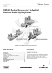
CSB400 Series Commercial / Industrial Pressure
Reducing Regulators
P1424
TYPE CSB400 PRESSURE
REDUCING REGULATOR
P1426
TYPICAL TYPE CSB403 REGULATOR WITH
INTEGRAL TRUE-MONITOR REGULATOR
P1425
TYPICAL TYPE CSB404 REGULATOR WITH
INTEGRAL TYPE VSX4 SLAM-SHUT MODULE
Figure 1. Typical CSB400 Series Pressure Reducing Regulator
Introduction
• Integral True-Monitor™—Regulator and Monitor
in One Unit
• Slam-shut
• Ductile Cast Iron and WCC Steel Bodies Available
• Wide Variety of Body Sizes and End Connections
• No Special Tools for Pressure Adjustment and
Orifice Removal
The CSB400 Series direct-operated, spring-loaded
regulatorshavebeenengineeredtofitamultitudeof
pressure-reducingapplicationsincludingcommercial
andindustrialinstallations.Thisflexibilityisprovided
bythenumerousbodysizesandendconnections,
outletpressuresettings,aswellastheoptionfor
internal,externalordualpressureregistration.In
additiontoapplicationflexibility,theCSB400Series
offersmultipleoverpressureprotectionoptionstomeet
yourdemandsonapplicationrequirements.
www.fisherregulators.com
D103137X012
Features and Benefits
Bulletin 71.1:CSB400
UPPER CASE
STABILIZER
GUIDE
REGULATOR CONTROL SPRING
HIGH TRIP
SPRING
LOW TRIP SPRING
VENT
VALVE STEM
ORIFICE
DIAPHRAGM
HEAD
PROXIMITY
SWITCH
PLUG
BALANCED PORT
ASSEMBLY
CAM
RESET
BUTTON
BODY
LEVER
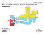
TOKEN RELIEF
SPRING
EXTERNAL CONTROL LINE OR
PRESSURE RETAINING PLUG
DIAPHRAGM
P1004
STABILIZER
Figure 2. Type CSB404 Regulator with Type VSX4 Slam-shut Internal View
Multiple Overpressure Protection
Options Available:
• Token Internal Relief -Providesrelieffrom
minoroverpressurecausedbynicksordentson
theorificeorbythermalexpansionofgasinthe
downstreamline.Tokenreliefalsoprovidesatoken
orsignal,intheformofodor,thatanoverpressure
situation is occurring.
2
• True-Monitor™ Protection -Combinesthe
operationofaconventionaltwo-regulatorwide-open
monitorsetintoonebody.
• Slam-Shut Protection - Discontinues gas
servicebyshuttingoffthegasflowifthereisan
overpressure or underpressure condition.
Bulletin 71.1:CSB400
Specifications
The Specifications section lists the specifications for the CSB400 Series Regulators. The following information is
stamped on the nameplate of CSB400 Series: Type and Class, Maximum Outlet Pressure and Spring Range.
Available Configurations
See Table 1
Body Sizes, Materials, End Connections and
Pressure Ratings(1)
See Table 2
Inlet Pressure Ratings(1)
See Table 3
Maximum Outlet Pressures(1)
Emergency Casing: 4.0 bar / 58 psig
To Avoid Internal Parts Damage:
All other Types: 0.34 bar / 5.0 psig above outlet
pressure setting
Type CSB450: 1 bar / 14.5 psig above outlet
pressure setting
Operating: 3.0 bar / 43.5 psig
Outlet Pressure Ranges(1)
17 mbar to 3.0 bar / 6.8 inches w.c. to 43.5 psig
See Table 5
Flow Capacities
See Tables 9 through 28
Orifice Size
17.5 mm / 11/16 inch
Operating Temperature (TS)(1)(2)
According to PED Standards:
All Types: -20 to 66°C / -4 to 150°F
Non-PED with Standard Construction:
Types CSB400/CSB404 and CSB420/CSB424:
-20 to 66°C / -4 to 150°F
Types CSB450/CSB454(3):
-30 to 66°C / -20 to 150°F
Non-PED with Standard Construction:
Types CSB400F/CSB404F(3) and
CSB420F/CB424F(3): -20 to 66°C / -4 to 150°F
Spring Case Vent Connection
1 NPT
Spring Case Vent and Body Orientation
See Figure 8
TM600 Series True-Monitor™ Performance
Inlet Pressure Ratings
Maximum Operating: Up to 8.62 bar / up to 125 psig
Maximum Emergency: 12.1 bar / 175 psig
Outlet Pressure Ranges: 27 mbar to 0.52 bar /
11 inches w.c. to 7.5 psig
Minimum Set Pressure: 20 mbar / 8 inches w.c.
Maximum Set Pressure: 0.41 bar / 6 psig
Type VSX4 Slam-Shut Device
Maximum Inlet Pressure: 20 bar / 290 psig
Maximum Operating Inlet Pressure: 16 bar / 232 psig
Flow and IEC Sizing Coefficients
See Table 3
Construction Materials
CSB400 Series Main Valve and Actuator
Body: Ductile Cast Iron and WCC Steel
Body O-ring: Nitrile (NBR)
Closing Cap and Adjusting Screw: Aluminum
Diaphragm Case, Spring Case, Diaphragm Plate and Valve Stem: Aluminum
Orifice: Aluminum
Pusher Post: Zinc-plated Steel
Relief Valve Seat: Aluminum
Diaphragm and Disk: Nitrile (NBR)
Control Spring: 302 Stainless steel
Relief Valve Spring: 302 Stainless Steel
Relief Valve Diaphragm Retainer: Steel
Vent Screen: 18-8 Stainless steel
Retainer Ring: Steel
Lever Pin: Stainless Steel
Spring Seat, Lever and Other Metal Parts: Steel
TM600 Series True-Monitor Actuator
Diaphragm Case, Spring Case, Diaphragm Plate and Valve Stem: Aluminum
Diaphragm and Disk: Nitrile (NBR)
Control Spring: 302 Stainless steel
Vent Screen: 18-8 Stainless steel
Vent Screen Retainer: Stainless steel
Closing Cap: Aluminum
Adjusting Screw: Aluminum
Type VSX4 Slam-shut Device
Diaphragm Case, Spring Case, Diaphragm Plate
and Valve Stem: Aluminum
Diaphragm and Disk: Nitrile (NBR)
Control Spring: Music Wire or 302 Stainless steel
Vent Screen: 18-8 Stainless steel
Vent Screen Retainer: Zinc-plated steel
Closing Cap: Aluminum
Adjusting Screw: Aluminum
Approximate Weights
with Threaded body
Type CSB400: 4 kg / 9 pounds
Type CSB403: 9 kg / 20 pounds
Type CSB404: 5 kg / 11 pounds
with Flanged body
Add 4 kg / 9 pounds to weights listed
Designed, Tested, and Evaluated Consistent With:
ANSI B16, ASME Section 8, ASTM B117
(Corrosion Resistance) and EN 334
1. The pressure/temperature limits in this Bulletin or any applicable standard limitation should not be exceeded.
2. Standard token relief set values listed in Table 8 are based on -20 to 60°C / -4 to 140°F.
3. Product has passed Fisher® testing for lockup, relief start-to-discharge and reseal down to -40°.
3
Bulletin 71.1:CSB400
Table 1. Available Configurations
TYPE NUMBER
C
S
B
OPTIONS
4
PRESSURE CONSTRUCTION AND UPSTREAM MONITOR APPLICATIONS
0
Low Pressure Applications (Outlet Pressure: 17 to 100 mbar / 7 to 40 inches w.c.)
1
Low Pressure, Upstream Monitoring Applications(1)(3) (Outlet Pressure: 17 to 100 mbar / 7 to 40 inches w.c.)
2
Medium Pressure Applications (Outlet Pressure: 100 to 517 mbar / 40 to 208 inches w.c.)
3
Medium Pressure, Upstream Monitoring Applications(1)(3) (Outlet Pressure: 100 to 517 mbar / 40 to 208 inches w.c.)
5
High Pressure Applications(2) (Outlet Pressure: 0.50 to 3.0 bar / 7 to 43.5 psig)
OVERPRESSURE PROTECTION
0
Without Overpressure Protection Module
0F
Low Temperature Capability, Without Overpressure Protection Module
3
With Integral True-MonitorTM Module(4)
3F
Low Temperature Capability, With Integral True-Monitor Module(4)
4
With Type VSX4 Slam-shut Module(5)
4F
Low Temperature Capability, With Type VSX4 Slam-shut Module(5)
PRESSURE REGISTRATION
D
Dual Registration (Best Solution for Quick Changing Loads)
E
External Registration
I
Internal Registration
RELIEF
N
No Relief
T
Internal Token Relief
Example: Type number CSB424DT: CSB400 Series regulator constructed for medium pressure applications, with Type VSX4 slam-shut module,
Dual pressure registration and Internal Token relief.
1. Not available with Integral True-Monitor option.
2. Not available with Integral True-Monitor or Token Relief option.
3. Available with External Pressure Registration only.
4. Reference Instruction Manual D103126X012 for information regarding the Type TM600 Integral True-Monitor module.
5. Reference Instruction Manual D103127X012 for information regarding the Type VSX4 Slam-shut module.
Table 2. Body Sizes, Material, End Connections and Pressure Ratings
BODY MATERIAL
Ductile Iron
WCC Steel
INLET SIZE
OUTLET SIZE
DN
NPS
DN
NPS
25
1
25
1
FACE-TO-FACE DIMENSION
mm
Inch
100
4
114
4.5
114
4.5
5
32
1-1/4
32
1-1/4
40
1-1/2
40
1-1/2
50
2
50
2
127
25
1
25
1
100
4
25
1
32
1-1/4
114
4.5
32
1-1/4
32
1-1/4
114
4.5
40
1-1/2
40
1-1/2
114
4.5
50
2
50
2
127
5
254
10
NPT
Rp
CL150 FF
BODY PRESSURE RATING
bar
psig
20
290
50
2
50
2
PN 10/16
254
10
16
232
40(1)
1-1/2(1)
40(1)
1-1/2(1)
PN 16 Slip-On
184
7.24
16
232
25
1
57
2-1/4
Rp x GAZ
105
4.1
25
1
25
1
32
1-1/4
32
1-1/4
40
1-1/2
40
20
290
25
1
25
32
1-1/4
32
1-1/4
40
1-1/2
40
1-1/2
1. Uses Rp 1-1/2 x 1-1/2 threaded body with PN 16 slip-on flanges.
4
END CONNECTION
100
4
114
4.5
1-1/2
114
4.5
1
100
4
114
4.5
114
4.5
NPT
Rp
Bulletin 71.1:CSB400
Table 3. Integral Strength (IS) Pressure Ratings (Applicable only to applications where inlet rating cannot exceed outlet rating)
MAXIMUM ALLOWABLE PRESSURE(1) /
MAXIMUM EMERGENCY INLET PRESSURE
TYPE
MAXIMUM OPERATING INLET PRESSURE(1)
PS
Pumax
bar
psig
bar
psig
4.0
58
4.0
58
CSB400, CSB400F, CSB404 and CSB404F
CSB420, CSB420F, CSB424 and CSB424F
CSB450 and CSB454
CSB410 and CSB414
CSB403, CSB403F, CSB423 and CSB423F
CSB403 and CSB423
1. For the Integral Strength (IS) version, the maximum value of PS and Pumax should be similar to the PSD used for the Differential Strength (DS) version.
Table 4. Differential Strength (DS) Pressure Ratings and Flow and Sizing Coefficients
TYPE
SPECIFIC MAXIMUM
ALLOWABLE
PRESSURE/MAXIMUM
EMERGENCY OUTLET
PRESSURE
MAXIMUM
OPERATING INLET
PRESSURE
MAXIMUM EMERGENCY
INLET PRESSURE(1)
PSD
Pumax
PS
bar
psig
bar
psig
CSB400F and CSB404F
bar
psig
6.0
87
12
174
CSB403F and CSB423F
6.0
87
10
145
10
145
10
145
ORIFICE
SIZE
FLOW
COEFFICIENTS
WIDE OPEN
IEC SIZING
COEFFICIENTS
mm
Inch
Cg
Cv
C1
Xt
FD
FL
17.5
11/16
428
11
43
1.16
0.84
0.90
CSB403 and CSB423
CSB410 and CSB414
CSB430 and CSB434
4.0
58
CSB400 and CSB404
CSB420F and CSB424F
CSB420 and CSB424
CSB450 and CSB454
10
145
12
174
16
232
20
290
1. If ordered with a PN 16 flanged connection, PS rating is a maximum of 16 bar / 232 psig. PS rating may be lower than 16 bar / 232 psig as indicated by this table.
Table 5. CSB400 Series Primary Regulator Outlet Pressure Ranges
TYPE
CBS400, CSB400F,
CSB403, CSB403F,
CSB404, CSB404F,
CSB410 and CSB414
CSB420, CSB420F,
CSB423, CSB423F,
CSB424, CSB424F,
CSB430 and CSB434
CSB450 and CSB454
OPERATING PRESSURE
RANGES, Wd
PART
NUMBER
SPRING
COLOR
SPRING
WIRE DIAMETER
SPRING
FREE LENGTH
mbar
Inch w.c.
mm
Inch
mm
Inch
17 to 24
6.8 to 9.6
GE30191X012
Pink
2.03
0.080
152
6.00
24 to 35
9.6 to 14
GE43955X012
Orange Stripe
2.19
0.086
110
4.35
35 to 60
14 to 24.1
GE30201X012
Dark Green
3.23
0.127
110
4.35
54 to 100
21.7 to 40
GE30202X012
Tan
2.85
0.112
127
5.00
100 to 160
1.45 to 2.3 psig
GE35081X012
Purple Stripe
3.86
0.152
124
4.90
138 to 300
2.0 to 4.4 psig
GE30192X012
Dark Blue
4.27
0.168
118
4.65
276 to 517
4 to 7.5 psig
GE33121X012
Red
4.93
0.194
118
4.65
500 mbar to 1 bar
7.3 to 14.5 psig
GE30203X012
Light Blue
5.59
0.220
102
4.00
1 to 3 bar
14.5 to 43.5 psig
GE30204X012
Light Green
6.73
0.265
100
3.95
Principle of Operations
Installation
Refer to Figures 4 and 5. When downstream demand
decreases, the pressure under the diaphragm
increases. This pressure overcomes the regulator
setting (which is set by a spring). Through the action
of the pusher post assembly, lever and valve stem,
the balanced port assembly moves closer to the
orifice and reduces gas flow. If demand downstream
increases, pressure under the diaphragm decreases.
Spring force pushes the pusher post assembly
downward and the balanced port assembly moves
away from the orifice.
The CSB400 Series regulators may be installed in
any position. However, the spring case vent should
be pointed downward. If gas escaping through the
CSB400 Series token internal relief valve could
constitute a hazard, the spring case vent must be piped
to a location where escaping gas will not be hazardous.
If the vented gas will be piped to another location,
obstruction-free tubing or piping at least equal to the
vent and the end of the vent pipe must be protected
from anything that might clog it. 5
Bulletin 71.1:CSB400
ADJUSTING SCREW
CONTROL SPRING
REGULATOR
ORIFICE
TOKEN RELIEF
SPRING
May 2008
PUSHER POST
Type CSB400IT Regulator with Token Relief
REGULATOR
DISK
LEVER
BALANCED PORT
ASSEMBLY
M1094
EXTERNAL
CONTROL LINE
(SENSE LINE)
VALVE STEM
INLET PRESSURE
INLET
PRESSURE
OUTLET PRESSURE
OUTLET
PRESSURE
ATMOSPHERIC PRESSURE
ATMOSPHERIC
PRESSURE
Figure 3. CSB400 Series with External Registration and Token Relief Operational Schematic
ADJUSTING SCREW
CONTROL SPRING
REGULATOR
ORIFICE
TOKEN RELIEF
SPRING
PUSHER POST
REGULATOR
DISK
LEVER
BALANCED PORT
ASSEMBLY
M1093
VALVE STEM
INLET
PRESSURE
INLET
PRESSURE
OUTLET
PRESSURE
OUTLET
PRESSURE
ATMOSPHERIC
PRESSURE
ATMOSPHERIC
PRESSURE
Figure 4. CSB400 Series with Internal Registration and Token Relief Operational Schematic
6
PRESSURE RETAINING
PLUG (DO NOT REMOVE
WHILE UNIT
IS PRESSURIZED)
Bulletin 71.1:CSB400
Pressure Registration and Downstream
Control Line Connection
Internal Registration
CSB400 Series regulators with an “IT” or “IN” in the
type number have internal pressure registration.
Internal registration utilizes an internal sense tube
located in the outlet of the body to communicate the
outlet pressure to the actuator chamber. Internal
registration is used for ease of installation. Response
time of the regulator is not as quick as dual registration
due to internal sense only having one sensing port
feeding the actuator chamber.
Dual Registration
CSB400 Series regulators with an “DT” or “DN” in the
type number have dual pressure registration. Dual
registration utilizes both internal sense and an external
downstream pressure registration line (control line)
connected to the 3/4 NPT control line tapping in the
lower diaphragm casing. By providing two channels
of pressure communication to the actuator, dual
registration provides the best method of pressure
registration for applications that exhibit quick changing
loads. Refer to the CSB400 Series Instruction Manual
for instruction regarding downstream control line
installation. The Type VSX4 slam-shut and Integral
Monitor have external pressure registration only and
require downstream control line installation. One
exception exists when the Primary regulator is installed
on a Rp 1 x 2-1/4 GAZ body, then the Type VSX4 slamshut has the option of internal pressure registration.
External Registration
CSB400 Series regulators with an “ET” or “EN” in
the type number have external pressure registration.
External registration utilizes a blocked throat, an
O-ring stem seal, and a 3/4 NPT control line tapping
in the lower diaphragm casing, Figure 3. A regulator
with a downstream control line is typically used for
monitoring installations or other applications where
there is an equipment installed between the regulator
and the pressure control point. The O-ring stem seal
separates the body pressure from diaphragm case
pressure on monitor installations where leakage cannot
be tolerated. Refer to the CSB400 Series Instruction
Manual for instruction regarding downstream control
line installation. The Type VSX4 slam-shut and Integral
Monitor have external pressure registration only and
require downstream control line installation. One
exception exists when the Primary regulator is installed
on a Rp 1 x 2-1/4 GAZ body, then the Type VSX4 slamshut has the option of internal pressure registration.
Internal Token Relief
CSB400 Series regulators with a “T” in the type
number, provide a low capacity or token internal relief to
help minimize overpressure. The token relief also acts
to avoid nuisance trips of the slam-shut mechanism
due to pressure increase from thermal expansion or
overpressure caused by orifice damage such as nicks
and dents.
Overpressure Protection
Overpressuring any portion of a regulator or
associated equipment may cause personal injury,
leakage or property damage due to bursting of
pressure-containing parts or explosion of accumulated
gas. Provide appropriate pressure relieving to ensure
that the critical limits in the Specification section are
not exceeded. Regulator operation within ratings does
not prevent the possibility of damage from external
sources or from debris in the pipeline.
The CSB400 Series regulators have outlet pressure
ratings that are lower than their inlet pressure ratings.
A pressure relieving or pressure limiting device is
needed for the CSB400 Series that do not have an
Integral Monitor or slam-shut device installed, or do
not have a separate upstream monitoring regulator
installed such as the Type CSB410.
Types CSB403 and CSB423 provide an integral
True-Monitor™ installed on the inlet side of the body that
serves to control downstream pressure if the primary
regulator ceases to control downstream pressure.
Types CSB404, CSB424 and CSB454 regulators rely
on Type VSX4 slam-shut device for overpressure
protection. In the event that outlet pressure rises above
or falls below the pressure setting of the Type VSX4,
the slam-shut device will activate or trip, thereby
stopping flow through to the downstream system. To
restart flow to the downstream system, the Type VSX4
must be reset. Type CSB404 regulators with a “T”
in their type number provide a low capacity (Token)
internal relief which provides sufficient relief to preclude
the Type VSX4 tripping due to pressure rise caused
by thermal expansion or overpressure due to orifice
damage such as nicks and dents.
Types CSB410 and CSB430 are monitor regulators
installed upstream of the Primary regulator. An external
control line is connected downstream of the Primary
regulator to provide protection if the Primary regulator
would cease to control downstream pressure.
Types CSB414 and CSB434 regulators act in
the same manner as the Types CSB410 and
CSB430 described previously, however, they also
provide additional overpressure protection to the
7
Bulletin 71.1:CSB400
REGULATOR
ADJUSTING SCREW
MONITOR ADJUSTING SCREW
REGULATOR ORIFICE
REGULATOR
CONTROL SPRING
MONITOR CONTROL SPRING
TOKEN RELIEF
SPRING
MONITOR DISK
EXTERNAL CONTROL
LINE (SENSE LINE)
MONITOR
LEVER
MONITOR
VALVE STEM
REGULATOR
VALVE STEM
MONITOR ORIFICE
MONITOR
OPENING SPRING
BALANCED PORT
ASSEMBLY
WIDE-OPEN INTEGRAL MONITOR REGULATOR
PRESSURE RETAINING
PLUG (DO NOT
REMOVE WHILE UNIT
REGULATOR
IS PRESSURIZED)
LEVER
REGULATOR
PUSHER POST
PRIMARY REGULATOR
M1098
INLET PRESSURE
INLET
PRESSURE
OUTLET PRESSURE
OUTLET
PRESSURE
ATMOSPHERIC PRESSURE
ATMOSPHERIC
PRESSURE
Figure 5. Type CSB403IT Internally Registered Primary Regulator with Externally Registered Integral Monitor Operational Schematic
Table 6. True-Monitor Protection vs. Backup Orifice Device
TYPE CSB403 TRUE-MONITOR
BACKUP ORIFICE DEVICE
Damage/nick on seat
X
X
Damage to disk
X
X
Damage or disconnected lever
X
----
Damage to diaphragm
X
----
Blocked or broken registration to primary regulator
X
----
1. As the Integral Monitor is externally registered, it is required that the Primary and Integral Wide-Open Monitor do not share downstream sense lines.
downstream system via a slam-shut that activates if
the downstream system pressure rises above or falls
PILOT SUPPLY PRESSURE
below INTERMEDIATE
the setpoint of the
slam-shut.
BLEED
PRESSURE
PRE-EXPANSION PRESSURE
VACUUM PRESSURE
Upstream
Monitoring Regulator
BYPASS PRESSURE
PRESSURE
Types PUMP
CSB410,
CSB414, CSB430 and CSB434
BACK PRESSURE
act as separate upstream monitoring regulators.
These upstream monitor regulators act in the same
manner as a Type CSB400 with external pressure
registration only, they are installed upstream of a
primary regulator. If the downstream Primary regulator
ceases to control the downstream system pressure
and downstream pressure begins to increase, this
pressure increase is registered underneath the
diaphragm of the Upstream Monitor regulator through
the downstream control line. The increased pressure
will overcome the force for the control spring and
cause the diaphragm assembly to move upward,
thereby moving the lever upward and moving the disk
closer to the orifice to regulate flow and downstream
system pressure.
8
Integral True-Monitor™ Protection
Types CSB403 and CSB423 combine the operation of
a conventional two-regulator wide-open monitor set into
one body. The Integral True-Monitor installed on the inlet
side of the body and serves to throttle flow and maintain
an acceptable downstream pressure in the case where
the Primary regulator ceases to control the downstream
pressure. Unlike multiple seat designs that rely on the
primary regulator for all failure modes, the Type CSB403
provides protection from a wide variety of occurrences
that could cause the Primary regulator not to regulate
downstream pressure. Table 6 shows a comparison
between the Integral True-Monitor protection and the
protection offered by an orifice backup device.
Refer to Figure 5. If the Primary regulator ceases to
control downstream pressure, outlet pressure will rise
underneath the diaphragm of the Integral monitor, which
will assume control of the downstream pressure.
Table 6 shows a comparison between the Integral
True-Monitor protection and the protection offered by
Bulletin 71.1:CSB400
OPSO ADJUSTING SCREW
UPSO ADJUSTING SCREW
OPSO SET SPRING
REGULATOR
ADJUSTING SCREW
UPSO SPRING
REGULATOR
CONTROL SPRING
SLAM-SHUT
ORIFICE
VENT
TOKEN RELIEF
SPRING
SCREW
PROXIMITY
SWITCH PLUG
RESET KNOB
SLAM-SHUT DISK
VALVE STEM
LEVER
REGULATOR ORIFICE
TYPE VSX4 SLAM-SHUT MODULE
M1146
EXTERNAL CONTROL
LINE (SENSE LINE)
PRIMARY REGULATOR
INLET
PRESSURE
INLET
PRESSURE
OUTLET
PRESSURE
OUTLET
PRESSURE
ATMOSPHERIC
PRESSURE
ATMOSPHERIC
PRESSURE
Figure 6. Type CSB404ET Externally Registered Regulator and Slam-Shut Operational Schematic
a backup orifice device, which seals on a secondary
seating surface should the primary orifice seating surface
or disk become damaged.
The Integral True-Monitor™ is externally registered and
will require a downstream control line. If the primary
regulator has internal registration, the monitor will still
require an external control line for pressure registration.
Token Relief
An optional token relief may be installed on the
primary regulator of the Type CSB403, denoted by the
“T” in the type number, for example, Type CSB403ET.
The token relief will be activated when the pressure
rises and activates the monitoring regulator in order
to provide an indication that the monitor is controlling
flow instead of the primary regulator.
Type VSX4 Slam-Shut Device
The Type VSX4 slam-shut device on the Type CSB404
regulator is a fast acting shutoff device that provides
overpressure (OPSO) or over and underpressure
(OPSO/UPSO) protection by shutting off the flow of
gas to the downstream system. The Type VSX4’s
actions are independent of the Type CSB404 regulator
and of variations to the inlet pressure. The Type VSX4
uses external pressure registration and requires a
downstream control line regardless if the regulator is
internally or externally registered.
Refer to the CSB400 Series Instruction Manual
for instruction regarding downstream control line
installation. The Type VSX4 slam-shut has an external
pressure registration only and requires downstream
control line installation. One exception exists when the
Primary regulator is installed on a Rp 1 x 2-1/4 GAZ
body, then the Type VSX4 slam-shut has the option of
internal pressure registration.
Refer to Figures 6 and 7, shutoff disk is normally
located in the open (reset) position. If the pressure
below the diaphragm increases (or decreases)
reaching the Type VSX4 setpoint, the diaphragm will
travel upwards (or downwards) to release the trip
mechanism which allows the spring force on the stem
will push the stem and disk against the seat, shutting
off all gas flow. The manual reset has an internal
bypass to equalize the reset pressure on either side
on the shutoff disk.
In order for the Underpressure Shutoff (UPSO) of
any slam-shut to be triggered, the downstream pipe
pressure must drop below the UPSO setpoint. In the
case of a downstream line break, numerous factors
can prevent the downstream pipe pressure from
decreasing below the slam-shut UPSO setpoint. These
factors include the distance of pipe to the break, the
diameter of the pipe, size of the break and the number
of restrictions, such as valves, elbows and bends,
downstream of the regulator and/or slam-shut device.
Due to these factors additional protections should be
installed to stop flow in the event of a line break.
9
Bulletin 71.1:CSB400
OPSO ADJUSTING SCREW
UPSO ADJUSTING SCREW
OPSO SET SPRING
REGULATOR
ADJUSTING SCREW
UPSO SPRING
REGULATOR
CONTROL SPRING
VENT
SLAM-SHUT
ORIFICE
TOKEN RELIEF
SPRING
PROXIMITY
SWITCH
PLUG
RESET KNOB
SLAM-SHUT DISK
LEVER
REGULATOR ORIFICE
TYPE VSX4 SLAM-SHUT MODULE
M1148
PRESSURE
RETAINING PLUG
(DO NOT REMOVE
WHILE UNIT
IS PRESSURIZED)
VALVE STEM
PRIMARY REGULATOR
INLET
PRESSURE
INLET
PRESSURE
OUTLET
PRESSURE
OUTLET
PRESSURE
ATMOSPHERIC
PRESSURE
ATMOSPHERIC
PRESSURE
Figure 7. Type CSB404IT Internally Registered Regulator with Externally Registered Slam-Shut Operational Schematic
Table 7. Primary Regulator and Integral Monitor Outlet Pressure Ranges
PRIMARY REGULATOR
Factory
Setpoint
TYPE
Set Pressure
Range
mbar
psig
mbar
psig
20
8 in. w.c.
17 to
24
6.8 to
9.6 in. w.c.
30
12 in. w.c.
CSB403
and
CB403F
50
69
138
CSB423
and
CB423F
207
345
20 in. w.c.
1
2
3
5
24 to
35
35 to
60
Factory Token Relief Set
Color
Part Number
% of
Reg. Set
mbar
psig
No Token Relief
Pink
170%
9.6 to
Orange
GE43955X012
14 in. w.c. Stripe
14 to
Dark
24 in. w.c. Green
Factory
Setpoint(1)
Spring Range
Color
Part Number
12 to
21 in. w.c.
Blue
GE30189X012
45 to
75
18 to
30 in. w.c.
Green
GE30196X012
1
65 to
99
26 to
40 in. w.c.
Orange
GE30225X012
103
1.5
97 to 200
1.4 to 2.9
Black
GE30190X012
138
2
97 to 200
1.4 to 2.9
Black
GE30190X012
172
2.5
97 to 200
1.4 to 2.9
Black
GE30190X012
241
3.5
197 to 255 2.6 to 3.7
Purple
GE35081X012
276
4
Dark Blue
GE30192X012
345
5
414
6
Red
GE33121X012
448
6.5
mbar
psig
mbar
psig
37
15 in. w.c.
30 to
52
52
21 in. w.c.
70
GE30191X012
35
14 in. w.c.
No Token Relief
150%
45
18 in. w.c.
No Token Relief
GE30201X012
140%
70
1
No Token Relief
54 to
100
0.78 to
1.45
Tan
100 to
160
1.45 to
2.3
Purple
Stripe
GE35081X012
138 to
300
2.0 to
4.4
Dark
Blue
GE30192X012
276 to
517
4 to
7.5
Red
GE33121X012
GE30202X012
130%
90
1.3
No Token Relief
130%
180
2.6
No Token Relief
248 to 414
125%
260
3.8
No Token Relief
1. Recommended minimum Integral True-Monitor setpoints shown.
10
INTEGRAL TRUE-MONITOR™
(1)
3.6 to 6
352 to 517 5.1 to 7.5
125%
430
6.25
Bulletin 71.1:CSB400
Table 8. Regulator and Slam-shut OPSO and UPSO Pressure Ranges
REGULATOR
SLAM-SHUT MODULE
Overpressure Shutoff (OPSO)
TYPE
CSB404,
CSB404F and
CSB414
CSB424,
CSB424F and
CSB434
CSB454(3)
Set Pressure
Range
mbar
psig
17 to
24
0.25 to
0.35
24 to
35
0.35 to
0.51
35 to
60
0.51 to
0.87
54 to
100
0.78 to
1.5
100 to
160
1.5 to
2.3
138 to
300
Standard
Setpoints
Token Relief
Set(1)(2)
Available
Minimum
Token Relief
Required
Range Shown
Standard
Difference
as a % of
OPSO Set
between
Regulator
Values(1) Pdso
Token Relief
Setpoint
and OPSO Set
Min(2)
Max
mbar
psig
170
215
8
0.12
mbar
psig
mbar
psig
20
0.29
34
0.49
psig
43
0.62
OPSO Set
Range as a %
of Regulator
Setpoint
Min
Max
215%
270%
Standard
UPSO Set
Values(1) Pdsu
mbar
psig
10
0.15
21
0.30
36
0.52
45
0.65
11
0.16
27
0.39
41
0.59
51
0.74
14
0.20
30
0.44
45
0.65
57
0.83
15
0.22
35
0.50
53
0.76
67
0.96
18
0.26
50
0.70
70
1.0
90
1.3
25
0.36
30
0.44
38
0.54
50
0.73
75
1.1
80
1.2
150
140
60
0.87
84
1.2
75
1.10
98
1.4
130
100
1.5
130
1.9
150
2.2
195
2.8
130
160
158
140
140
10
16
20
40
160
2.3
208
3.0
2.0 to
4.4
300
4.4
375
5.4
125
140
50
276 to
517
4.0 to
7.5
500
7.3
625
9.1
125
140
500 to
1000
7.3 to
14.5
1000
14.5
----
----
----
1200
17.4
----
----
1500
21.6
----
2000
29.0
3000
43.5
1000 to 14.5 to
3000
43.5
mbar
Underpressure Shutoff (UPSO)
0.12
0.23
190%
180%
108
1.57
128
1.85
0.29
170%
170
2.47
248
3.59
0.58
165%
200%
200%
190%
UPSO Set
Range as a %
of Regulator
Setpoint
Min
Max
50
56
50
60
50
70
50
70
50
70
50
70
175%
264
3.83
0.73
450
6.53
150%
165%
150
2.2
60
0.87
700
10.2
140%
180%
250
3.6
----
----
----
1320
19.2
112%
140%
500
7.3
----
----
----
----
1600
23.2
112%
133%
600
8.7
----
----
----
----
----
1900
27.6
112%
127%
750
10.9
----
----
----
----
----
----
2400
34.8
112%
120%
1000
14.5
----
----
----
----
----
----
3400
49.3
112%
113%
1500
21.8
1. Standard factory set shown. Factory set is at the Minimum value of the range indicated. Range indicated is a percentage of Setpoint. Percentage indicated is based on the Set Pressure
Range in which that setpoint resides. If non-standard sets are required, adherence must be made to constraints shown in Table 7, including Token Relief Set Range, OPSO and UPSO set
range and Minimum Required difference between Token Relief and OPSO Set.
2. Minimum Token Relief values apply to -20 to 60°C / -4 to 140°F service temperatures. For service below -20°C / -4°F, add 8 mbar / 0.12 psig to the minimum Token Relief value listed.
3. Token Relief is not available for the Type CSB454.
Example: If a non-standard setpoint is needed, see the following example for instruction in using Table 8.
Non-standard setpoint = 140 mbar / 2 psig, then the factory set of the token relief will be 1.3*140 = 182 mbar /
2.6 psig. The factory OPSO and UPSO set values will be 165% of set and 50% of set, respectively, resulting is
values of 231 mbar / 3.4 psig and 70 mbar / 1 psig, also respective to OPSO and UPSO.
11
Bulletin 71.1:CSB400
Capacity Information
appropriate conversion factor: 0.775 for air, 0.628 for
propane, 0.548 for butane or 0.789 for nitrogen. For
gases of other specific gravities, multiply the given
capacity by 0.775 and divide by the square root of the
appropriate specific gravity.
Tables 9 through 28 provide natural gas regulating
capacities at selected inlet pressures and outlet
pressure settings for the CSB400 Series, which
includes configurations that include the Integral
Monitor and Slam-shut. Flows are in SCMH (16°C and
1.01325 bar) and SCFH (60°F and 14.7 psia) of 0.6
specific gravity natural gas. To determine equivalent
capacities for air, propane, butane or nitrogen, multiply
the capacity number in the tables by the following
The published capacities were obtained using inlet
and outlet piping the same size as the regulator
body size.
Table 9. CSB400 Series Internal and Dual Sense (Pressure Registration) Flow Capacities for 20 mbar / 8 inches w.c. Setpoint, AC 10 Accuracy
ACCURACY AC 10%
SETPOINT
Droop
Boost
SET RANGE
20 mbar
-2 mbar
2 mbar
17 to 24 mbar
8 inches w.c.
PART NUMBER COLOR
-0.80 inches w.c. 0.80 inches w.c. 6.8 to 9.6 inches w.c.
GE30191X012
Pink
METHOD OF DOWNSTREAM SENSE (PRESSURE REGISTRATION)
Internal Sense
INLET PRESSURE
Dual Sense (Combined Internal and External)
Body Outlet Size
DN 25 / NPS 1
Body Outlet Size
DN 32 / NPS 1-1/4
DN 40 / NPS 1-1/2
2-1/4 GAZ(1)
DN 25 / NPS 1
DN 32 / NPS 1-1/4
DN 40 / NPS 1-1/2
bar
psig
Sm3/h
SCFH
Sm3/h
SCFH
Sm3/h
SCFH
Sm3/h
SCFH
Sm3/h
SCFH
Sm3/h
SCFH
Sm3/h
SCFH
0.10
0.20
0.30
0.40
0.50
0.75
1.00
2.0
3.0
4.0
5.0
1.5
2.9
4.4
5.8
7.3
10.9
14.5
29
44
58
73
42
71
112
112
112
112
112
112
85
85
85
1483
2507
3955
3955
3955
3955
3955
3955
3001
3001
3001
45
65
90
120
160
160
160
130
120
120
120
1589
2295
3178
4237
5650
5650
5650
4590
4237
4237
4237
40
60
85
100
140
208
208
208
208
105
105
1412
2118
3001
3531
4944
7345
7345
7345
7345
3708
3708
40
90
129
153
160
160
160
160
198
198
198
1412
3178
4555
5403
5650
5650
5650
5650
6992
6992
6992
41
57
85
100
129
129
129
183
183
183
183
1447
2012
3001
3531
4555
4555
4555
6462
6462
6462
6462
41
60
88
104
150
171
208
268
268
268
268
1447
2118
3107
3672
5297
6038
7345
9464
9464
9464
9464
41
62
89
103
151
176
208
350
402
402
402
1447
2189
3143
3637
5332
6215
7345
12,360
14,196
14,196
14,196
1. External thread (DN 50 / NPS 2 pipe size).
- Gray areas indicate limited due to dynamic flow effects (Boost).
Table 10. CSB400 Series Internal and Dual Sense (Pressure Registration) Flow Capacities for 30 mbar / 12 inches w.c. Setpoint,
AC 10 Accuracy
ACCURACY AC 10%
SETPOINT
Droop
Boost
SET RANGE
30 mbar
-3 mbar
3 mbar
24 to 35 mbar
12 inches w.c.
-1.2 inches w.c.
1.2 inches w.c. 9.6 to 14 inches w.c.
PART NUMBER
COLOR
GE43955X012
Orange
Stripe
METHOD OF DOWNSTREAM SENSE (PRESSURE REGISTRATION)
Internal Sense
INLET PRESSURE
DN 25 / NPS 1
Body Outlet Size
DN 32 / NPS 1-1/4
DN 40 / NPS 1-1/2
2-1/4 GAZ(1)
DN 25 / NPS 1
DN 32 / NPS 1-1/4
DN 40 / NPS 1-1/2
bar
psig
Sm3/h
SCFH
Sm3/h
SCFH
Sm3/h
SCFH
Sm3/h
SCFH
Sm3/h
SCFH
Sm3/h
SCFH
Sm3/h
SCFH
0.10
0.20
0.30
0.40
0.50
0.75
1.00
2.0
3.0
4.0
5.0
1.5
2.9
4.4
5.8
7.3
10.9
14.5
29
44
58
73
53
91
118
130
130
130
130
130
100
100
100
1871
3213
4167
4590
4590
4590
4590
4590
3531
3531
3531
54
80
115
135
160
185
185
185
165
155
155
1906
2825
4061
4767
5650
6533
6533
6533
5826
5473
5473
56
85
115
141
160
205
205
205
105
105
105
1977
3001
4061
4979
5650
7239
7239
7239
3708
3708
3708
56
96
119
145
169
169
194
212
215
240
240
1977
3390
4202
5120
5968
5968
6851
7486
7592
8475
8475
45
75
95
115
138
170
170
312
340
340
298
1589
2648
3354
4061
4873
6003
6003
11,018
12,006
12,006
10,523
49
76
95
115
138
185
210
340
380
380
380
1730
2683
3354
4061
4873
6533
7416
12,006
13,419
13,419
13,419
55
80
104
123
147
192
210
342
400
400
400
1942
2825
3672
4343
5191
6780
7416
12,077
14,125
14,125
14,125
1. External thread (DN 50 / NPS 2 pipe size).
- Gray areas indicate limited capacities due to boost effects.
12
Dual Sense (Combined Internal and External)
Body Outlet Size
Bulletin 71.1:CSB400
Table 11. C
SB400 Series Internal and Dual Sense (Pressure Registration) Flow Capacities for 50 mbar / 20 inches w.c. Setpoint,
AC 10 Accuracy
SETPOINT
50 mbar
20 inches w.c.
ACCURACY AC 10%
Droop
Boost
SET RANGE
PART NUMBER
COLOR
-5 mbar
5 mbar
35 to 60 mbar
GE30201X012 Dark Green
-2.0 inches w.c. 2.0 inches w.c. 14 to 24 inches w.c.
METHOD OF DOWNSTREAM SENSE (PRESSURE REGISTRATION)
Internal Sense
Dual Sense (Combined Internal and External)
Body Outlet Size
Body Outlet Size
DN 32 / NPS 1-1/4
DN 40 / NPS 1-1/2
2-1/4 GAZ(1)
DN 25 / NPS 1
DN 32 / NPS 1-1/4
DN 40 / NPS 1-1/2
Sm3/h
SCFH
Sm3/h
SCFH
Sm3/h
SCFH
Sm3/h
SCFH
Sm3/h
SCFH
Sm3/h
SCFH
25
882
30
1059
32
1130
30
1059
28
988
26
918
50
1765
49
1730
56
1977
50
1765
46
1624
50
1765
65
2295
73
2577
80
2825
69
2436
70
2472
64
2260
85
3001
81
2860
100
3531
85
3001
81
2860
82
2895
105
3708
102
3602
150
5297
102
3602
98
3460
98
3460
155
5473
140
4944
205
7239
146
5155
133
4696
129
4555
205
7239
183
6462
285
10,064
197
6956
163
5756
148
5226
300
10,594
325
11,477
325
11,477
364
12,854
287
10,135
290
10,241
300
10,594
325
11,477
345
12,183
364
12,854
445
15,715
470
16,597
300
10,594
325
11,477
345
12,183
364
12,854
445
15,715
470
16,597
300
10,594
325
11,477
345
12,183
364
12,854
445
15,715
470
16,597
INLET PRESSURE
DN 25 / NPS 1
bar
psig
Sm3/h
SCFH
0.10
1.5
33
1165
0.20
2.9
58
2048
0.30
4.4
87
3072
0.40
5.8
114
4025
0.50
7.3
140
4944
0.75
10.9
195
6886
1.00
14.5
195
6886
2.0
29
195
6886
3.0
44
195
6886
4.0
58
188
6639
5.0
73
188
6639
1. External thread (DN 50 / NPS 2 pipe size).
- Gray areas indicate limited capacities due to boost effects. Table 12. C
SB400 Series Internal and Dual Sense (Pressure Registration) Flow Capacities for 75 mbar / 30 inches w.c. Setpoint,
AC 10 Accuracy
SETPOINT
75 mbar
30 inches w.c.
ACCURACY AC 10%
Droop
Boost
SET RANGE
PART NUMBER
-7.5 mbar
7.5 mbar
54 to 100 mbar
GE30202X012
-3.0 inches w.c. 3.0 inches w.c. 21.7 to 40 inches w.c.
DN 25 / NPS 1
psig
Tan
METHOD OF DOWNSTREAM SENSE (PRESSURE REGISTRATION)
Internal Sense
Dual Sense (Combined Internal and External)
Body Outlet Size
Body Outlet Size
INLET PRESSURE
bar
COLOR
Sm /h
3
SCFH
DN 32 / NPS 1-1/4
DN 40 / NPS 1-1/2
DN 32 / NPS 1-1/4
DN 40 / NPS 1-1/2
Sm /h
Sm /h
SCFH
Sm3/h
SCFH
Sm3/h
SCFH
Sm3/h
SCFH
Sm3/h
SCFH
65
86
103
128
167
221
383
383
383
383
2295
3037
3637
4520
5897
7804
13,525
13,525
13,525
13,525
82
116
144
189
253
310
366
405
430
430
2895
4096
5085
6674
8934
10,947
12,925
14,302
15,185
15,185
65
88
111
130
173
216
367
367
367
367
2295
3107
3919
4590
6109
7627
12,960
12,960
12,960
12,960
65
90
112
130
173
216
367
367
367
367
2295
3178
3955
4590
6109
7627
12,960
12,960
12,960
12,960
60
84
102
120
161
203
360
491
491
491
2118
2966
3602
4237
5685
7168
12,713
17,339
17,339
17,339
3
SCFH
0.20
2.9
66
2330
67
2366
0.30
4.4
99
3496
90
3178
0.40
5.8
190
6709
115
4061
0.50
7.3
156
5509
135
4767
0.75
10.9
206
7274
190
6709
1.00
14.5
252
8899
247
8722
2.0
29
252
8899
375
13,243
3.0
44
252
8899
375
13,243
4.0
58
252
8899
375
13,243
5.0
73
222
7839
375
13,243
1. External thread (DN 50 / NPS 2 pipe size).
- Gray areas indicate limited capacities due to boost effects.
3
2-1/4 GAZ(1)
DN 25 / NPS 1
Table 13. CSB400 Series Internal and Dual Sense (Pressure Registration) Flow Capacities for 100 mbar / 40 inches w.c. Setpoint,
AC 5 Accuracy
SETPOINT
100 mbar
40 inches w.c
ACCURACY AC 5%
Droop
Boost
SET RANGE
PART NUMBER
-5.0 mbar
5.0 mbar
54 to 100 mbar
GE30202X012
-2.0 inches w.c. 2.0 inches w.c. 21.7 to 40 inches w.c.
DN 25 / NPS 1
psig
Tan
METHOD OF DOWNSTREAM SENSE (PRESSURE REGISTRATION)
Internal Sense
Dual Sense (Combined Internal and External)
Body Outlet Size
Body Outlet Size
INLET PRESSURE
bar
COLOR
Sm3/h
SCFH
0.20
2.9
41
1447
0.30
4.4
65
2295
0.40
5.8
86
3037
0.50
7.3
122
4308
0.75
10.9
182
6427
1.00
14.5
182
6427
2.0
29
182
6427
3.0
44
195
6886
4.0
58
195
6886
5.0
73
195
6886
1. External thread (DN 50 / NPS 2 pipe size).
DN 32 / NPS 1-1/4
DN 40 / NPS 1-1/2
2-1/4 GAZ(1)
DN 32 / NPS 1-1/4
DN 40 / NPS 1-1/2
Sm3/h
SCFH
Sm3/h
SCFH
Sm3/h
SCFH
Sm3/h
DN 25 / NPS 1
SCFH
Sm3/h
SCFH
Sm3/h
SCFH
36
56
73
93
135
180
295
295
295
295
1271
1977
2577
3284
4767
6356
10,417
10,417
10,417
10,417
38
53
69
83
120
155
348
348
348
348
1341
1871
2436
2931
4237
5473
12,289
12,289
12,289
12,289
32
45
54
59
110
265
380
436
440
440
1130
1589
1906
2083
3884
9358
13,419
15,397
15,538
15,538
40
60
75
94
135
180
330
330
330
330
1412
2118
2648
3319
4767
6356
11,653
11,653
11,653
11,653
37
60
72
84
118
151
281
420
420
420
1306
2118
2542
2966
4167
5332
9923
14,832
14,832
14,832
34
51
63
75
107
131
253
420
440
440
1200
1801
2224
2648
3778
4626
8934
14,832
15,538
15,538
13
Bulletin 71.1:CSB400
Table 14. C
SB400 Series Internal and Dual Sense (Pressure Registration) Flow Capacities for 100 mbar / 40 inches w.c. Setpoint,
AC 10 Accuracy
SETPOINT
100 mbar
40 inches w.c.
ACCURACY AC 10%
Droop
Boost
SET RANGE
PART NUMBER
-10 mbar
10 mbar
54 to 100 mbar
GE30202X012
-4.0 inches w.c. 4.0 inches w.c. 21.7 to 40 inches w.c.
INLET PRESSURE
DN 25 / NPS 1
bar
psig
Sm3/h
SCFH
0.20
2.9
65
2295
0.30
4.4
97
3425
0.40
5.8
122
4308
0.50
7.3
148
5226
0.75
10.9
202
7133
1.00
14.5
221
7804
2.0
29
251
8863
3.0
44
251
8863
4.0
58
251
8863
5.0
73
251
8863
1. External thread (DN 50 / NPS 2 pipe size).
COLOR
Tan
METHOD OF DOWNSTREAM SENSE (PRESSURE REGISTRATION)
Internal Sense
Dual Sense (Combined Internal and External)
Body Outlet Size
Body Outlet Size
DN 32 / NPS 1-1/4
DN 40 / NPS 1-1/2
2-1/4 GAZ(1)
DN 25 / NPS 1
DN 32 / NPS 1-1/4
DN 40 / NPS 1-1/2
Sm3/h
SCFH
Sm3/h
SCFH
Sm3/h
SCFH
Sm3/h
SCFH
Sm3/h
SCFH
Sm3/h
SCFH
60
2118
38
1341
54
1906
64
2260
65
2295
66
2330
96
3390
53
1871
74
2613
94
3319
100
3531
94
3319
121
4273
69
2436
102
3602
114
4025
121
4273
119
4202
156
5509
83
2931
123
4343
141
4979
143
5049
137
4838
204
7204
120
4237
212
7486
189
6674
194
6851
183
6462
257
9075
155
5473
300
10,594
229
8087
238
8404
222
7839
445
15,715
348
12,289
478
16,880
366
12,925
407
14,373
373
13,172
460
16,244
478
16,880
478
16,880
513
18,116
515
18,187
515
18,187
460
16,244
520
18,363
520
18,363
513
18,116
570
20,129
646
22,813
460
16,244
568
20,058
580
20,482
513
18,116
570
20,129
646
22,813
Table 15. C
SB400 Series Internal and Dual Sense (Pressure Registration) Flow Capacities for 150 mbar / 2.2 psig Setpoint,
AC 5 Accuracy
SETPOINT
150 mbar
2.2 psig
ACCURACY AC 5%
Droop
Boost
-7.5 mbar
7.5 mbar
-3.0 inches w.c. 3.0 inches w.c.
SET RANGE
100 to 160 mbar
1.45 to 2.3 psig
PART NUMBER
COLOR
GE35081X012
Purple Stripe
METHOD OF DOWNSTREAM SENSE (PRESSURE REGISTRATION)
Internal Sense
Dual Sense (Combined Internal and External)
Body Outlet Size
Body Outlet Size
DN 32 / NPS 1-1/4
DN 40 / NPS 1-1/2
2-1/4 GAZ(1)
DN 25 / NPS 1
DN 32 / NPS 1-1/4
DN 40 / NPS 1-1/2
Sm3/h
SCFH
Sm3/h
SCFH
Sm3/h
SCFH
Sm3/h
SCFH
Sm3/h
SCFH
Sm3/h
SCFH
65
2295
62
2189
65
2295
65
2295
67
2366
68
2401
85
3001
86
3037
95
3354
86
3037
84
2966
80
2825
105
3708
105
3708
125
4414
108
3813
108
3813
99
3496
165
5826
155
5473
200
7062
153
5403
152
5367
135
4767
215
7592
190
6709
265
9358
200
7062
190
6709
177
6250
340
12,006
344
12,148
365
12,889
347
12,254
356
12,572
279
9852
415
14,655
425
15,008
410
14,479
475
16,774
490
17,304
490
17,304
415
14,655
425
15,008
425
15,008
475
16,774
490
17,304
520
18,363
375
13,243
425
15,008
425
15,008
475
16,774
490
17,304
520
18,363
INLET PRESSURE
DN 25 / NPS 1
bar
psig
Sm3/h
SCFH
0.30
4.4
71
2507
0.40
5.8
99
3496
0.50
7.3
130
4590
0.75
10.9
196
6921
1.00
14.5
245
8652
2.0
29
272
9605
3.0
44
253
8934
4.0
58
215
7592
5.0
73
215
7592
1. External thread (DN 50 / NPS 2 pipe size).
- Gray areas indicate limited capacities due to boost effects.
Table 16. C
SB400 Series Internal and Dual Sense (Pressure Registration) Flow Capacities for 150 mbar / 2.2 psig Setpoint,
AC 10 Accuracy
SETPOINT
150 mbar
2.2 psig
ACCURACY AC 10%
Droop
Boost
-15 mbar
15 mbar
-0.22 psig
0.22 psig
INLET PRESSURE
DN 25 / NPS 1
bar
psig
Sm3/h
SCFH
0.30
4.4
97
3425
0.40
5.8
126
4449
0.50
7.3
151
5332
0.75
10.9
200
7062
1.00
14.5
247
8722
2.0
29
316
11,159
3.0
44
316
11,159
4.0
58
316
11,159
5.0
73
316
11,159
1. External thread (DN 50 / NPS 2 pipe size).
14
SET RANGE
100 to 160 mbar
1.45 to 2.3 psig
PART NUMBER
COLOR
GE35081X012
Purple Stripe
METHOD OF DOWNSTREAM SENSE (PRESSURE REGISTRATION)
Internal Sense
Dual Sense (Combined Internal and External)
Body Outlet Size
Body Outlet Size
DN 32 / NPS 1-1/4
DN 40 / NPS 1-1/2
2-1/4 GAZ(1)
DN 25 / NPS 1
DN 32 / NPS 1-1/4
DN 40 / NPS 1-1/2
Sm3/h
SCFH
Sm3/h
SCFH
Sm3/h
SCFH
Sm3/h
SCFH
Sm3/h
SCFH
Sm3/h
SCFH
100
3531
105
3708
95
3354
96
3390
97
3425
104
3672
130
4590
122
4308
130
4590
123
4343
124
4379
119
4202
160
5650
151
5332
160
5650
146
5155
150
5297
143
5049
210
7416
196
6921
215
7592
200
7062
207
7310
189
6674
255
9005
228
8051
265
9358
243
8581
261
9217
223
7875
445
15,715
354
12,501
445
15,715
354
12,501
439
15,503
311
10,982
520
18,363
560
19,776
475
16,774
516
18,222
520
18,363
528
18,646
520
18,363
560
19,776
530
18,716
516
18,222
520
18,363
528
18,646
520
18,363
560
19,776
590
20,835
516
18,222
520
18,363
528
18,646
Bulletin 71.1:CSB400
Table 17. C
SB400 Series Internal and Dual Sense (Pressure Registration) Flow Capacities for 300 mbar / 4.4 psig Setpoint,
AC 5 Accuracy
ACCURACY AC 5%
Droop
Boost
-15 mbar
15 mbar
-0.2 psig
0.2 psig
SETPOINT
300 mbar
4.4 psig
INLET PRESSURE
DN 25 / NPS 1
bar
psig
Sm3/h
SCFH
0.40
5.8
64
2260
0.50
7.3
87
3072
0.75
10.9
145
5120
1.00
14.5
206
7274
2.0
29
392
13,843
3.0
44
468
16,527
4.0
58
468
16,527
5.0
73
469
16,562
1. External thread (DN 50 / NPS 2 pipe size).
SET RANGE
138 to 300 mbar
2.0 to 4.4 psig
PART NUMBER
COLOR
GE30192X012
Dark Blue
METHOD OF DOWNSTREAM SENSE (PRESSURE REGISTRATION)
Internal Sense
Dual Sense (Combined Internal and External)
Body Outlet Size
Body Outlet Size
(1)
DN 32 / NPS 1-1/4
DN 40 / NPS 1-1/2
2-1/4 GAZ
DN 25 / NPS 1
DN 32 / NPS 1-1/4
DN 40 / NPS 1-1/2
Sm3/h
SCFH
Sm3/h
SCFH
Sm3/h
SCFH
Sm3/h
SCFH
Sm3/h
SCFH
Sm3/h
SCFH
65
2295
60
2118
55
1942
65
2295
66
2330
55
1942
90
3178
84
2966
85
3001
85
3001
87
3072
83
2931
140
4944
131
4626
130
4590
128
4520
135
4767
128
4520
175
6180
168
5932
190
6709
166
5862
170
6003
163
5756
375
13,243
325
11,477
440
15,538
290
10,241
330
11,653
305
10,770
580
20,482
512
18,081
580
20,482
423
14,938
435
15,361
440
15,538
580
20,482
580
20,482
580
20,482
423
14,938
468
16,527
500
17,657
580
20,482
580
20,482
580
20,482
423
14,938
468
16,527
500
17,657
Table 18. C
SB400 Series Internal and Dual Sense (Pressure Registration) Flow Capacities for 300 mbar / 4.4 psig Setpoint,
AC 10 Accuracy
ACCURACY AC 10%
Droop
Boost
-30 mbar
30 mbar
-0.4 psig
0.4 psig
SETPOINT
300 mbar
4.4 psig
INLET PRESSURE
DN 25 / NPS 1
bar
psig
Sm3/h
SCFH
0.40
5.8
100
3531
0.50
7.3
125
4414
0.75
10.9
183
6462
1.00
14.5
234
8263
2.0
29
397
14,019
3.0
44
515
18,187
4.0
58
605
21,365
5.0
73
605
21,365
1. External thread (DN 50 / NPS 2 pipe size).
SET RANGE
138 to 300 mbar
2.0 to 4.4 psig
PART NUMBER
COLOR
GE30192X012
Dark Blue
METHOD OF DOWNSTREAM SENSE (PRESSURE REGISTRATION)
Internal Sense
Dual Sense (Combined Internal and External)
Body Outlet Size
Body Outlet Size
DN 32 / NPS 1-1/4
DN 40 / NPS 1-1/2
2-1/4 GAZ(1)
DN 25 / NPS 1
DN 32 / NPS 1-1/4
DN 40 / NPS 1-1/2
Sm3/h
SCFH
Sm3/h
SCFH
Sm3/h
SCFH
Sm3/h
SCFH
Sm3/h
SCFH
Sm3/h
SCFH
100
3531
96
3390
100
3531
99
3496
107
3778
98
3460
135
4767
126
4449
125
4414
126
4449
137
4838
114
4025
195
6886
175
6180
190
6709
184
6497
197
6956
167
5897
250
8828
224
7910
255
9005
229
8087
245
8652
208
7345
435
15,361
372
13,137
450
15,891
380
13,419
418
14,761
363
12,819
525
18,540
552
19,493
615
21,718
496
17,516
587
20,729
541
19,105
610
21,541
705
24,896
720
25,426
615
21,718
620
21,895
676
23,872
610
21,541
705
24,896
720
25,426
615
21,718
620
21,895
676
23,872
Table 19. C
SB400 Series Internal and Dual Sense (Pressure Registration) Flow Capacities for 500 mbar / 7.3 psig Setpoint,
AC 5 Accuracy
SETPOINT
500 mbar
7.3 psig
ACCURACY AC 5%
Droop
Boost
-25 mbar
25 mbar
-0.36 psig
0.36 psig
INLET PRESSURE
bar
0.75
1.00
2.0
3.0
4.0
5.0
8.0
10
12
16
psig
10.9
14.5
29
44
58
73
116
145
174
232
DN 25 / NPS 1
Sm3/h
SCFH
113
3990
170
6003
385
13,596
518
18,292
660
23,307
660
23,307
433
15,291
420
14,832
420
14,832
408
14,408
SET RANGE
276 to 517 mbar
4 to 7.5 psig
PART NUMBER
COLOR
GE33121X012
Red
METHOD OF DOWNSTREAM SENSE (PRESSURE REGISTRATION)
Internal Sense
Dual Sense (Combined Internal and External)
Body Outlet Size
Body Outlet Size
DN 32 / NPS 1-1/4
DN 40 / NPS 1-1/2
DN 25 / NPS 1
DN 32 / NPS 1-1/4
DN 40 / NPS 1-1/2
Sm3/h
SCFH
Sm3/h
SCFH
Sm3/h
SCFH
Sm3/h
SCFH
Sm3/h
SCFH
116
4096
123
4343
109
3849
115
4061
114
4025
165
5826
160
5650
155
5473
164
5791
159
5615
341
12,042
320
11,300
302
10,665
336
11,865
311
10,982
530
18,716
502
17,727
385
13,596
509
17,975
465
16,421
692
24,437
638
22,530
522
18,434
656
23,166
600
21,188
770
27,192
800
28,251
625
22,071
823
29,063
765
27,015
770
27,192
800
28,251
650
22,954
823
29,063
845
29,840
770
27,192
800
28,251
650
22,954
823
29,063
845
29,840
770
27,192
800
28,251
650
22,954
823
29,063
845
29,840
770
27,192
800
28,251
650
22,954
823
29,063
845
29,840
- Gray areas indicate limited capacities due to boost effects.
15
Bulletin 71.1:CSB400
Table 20. C
SB400 Series Internal and Dual Sense (Pressure Registration) Flow Capacities for 500 mbar / 7.3 psig Setpoint,
AC 10 Accuracy
SETPOINT
500 mbar
7.3 psig
ACCURACY AC 10%
Droop
Boost
-50 mbar
50 mbar
-0.7 psig
0.7 psig
INLET PRESSURE
bar
0.75
1.0
2.0
3.0
4.0
5.0
8.0
10
12
16
psig
10.9
14.5
29
44
58
73
116
145
174
232
DN 25 / NPS 1
Sm3/h
SCFH
155
5473
215
7592
408
14,408
528
18,646
615
21,718
615
21,718
615
21,718
600
21,188
600
21,188
595
21,012
SET RANGE
276 to 517 mbar
4 to 7.5 psig
PART NUMBER
COLOR
GE33121X012
Red
METHOD OF DOWNSTREAM SENSE (PRESSURE REGISTRATION)
Internal Sense
Dual Sense (Combined Internal and External)
Body Outlet Size
Body Outlet Size
DN 32 / NPS 1-1/4
DN 40 / NPS 1-1/2
DN 25 / NPS 1
DN 32 / NPS 1-1/4
DN 40 / NPS 1-1/2
3
3
3
Sm /h
SCFH
Sm /h
SCFH
Sm /h
SCFH
Sm3/h
SCFH
Sm3/h
SCFH
169
5968
153
5403
159
5615
169
5968
165
5826
231
8157
206
7274
210
7416
231
8157
210
7416
424
14,973
387
13,666
373
13,172
416
14,690
374
13,207
602
21,259
545
19,246
482
17,021
539
19,034
545
19,246
754
26,627
673
23,766
604
21,330
752
26,556
704
24,861
820
28,958
852
30,088
701
24,755
922
32,560
856
30,229
820
28,958
905
31,959
701
24,755
922
32,560
955
33,725
820
28,958
905
31,959
701
24,755
922
32,560
955
33,725
820
28,958
905
31,959
701
24,755
922
32,560
955
33,725
820
28,958
905
31,959
701
24,755
922
32,560
955
33,725
- Gray areas indicate limited capacities due to boost effects.
Table 21. C
SB400 Series Internal and Dual Sense (Pressure Registration) Flow Capacities for 0.75 bar / 10.9 psig Setpoint,
AC 5 Accuracy
SETPOINT
0.75 bar
10.9 psig
ACCURACY AC 5%
Droop
Boost
-37.5 mbar
37.5 mbar
-0.5 psig
0.5 psig
INLET PRESSURE
bar
1.00
2.0
3.0
4.0
5.0
8.0
10
12
16
psig
14.5
29
44
58
73
116
145
174
232
DN 25 / NPS 1
Sm3/h
SCFH
58
2048
117
4131
205
7239
335
11,830
650
22,954
705
24,896
705
24,896
705
24,896
705
24,896
SET RANGE
0.50 to 1.00 bar
7.3 to 14.5 psig
PART NUMBER
COLOR
GE30203X012
Light Blue
METHOD OF DOWNSTREAM SENSE (PRESSURE REGISTRATION)
Internal Sense
Dual Sense (Combined Internal and External)
Body Outlet Size
Body Outlet Size
DN 32 / NPS 1-1/4
DN 40 / NPS 1-1/2
DN 25 / NPS 1
DN 32 / NPS 1-1/4
DN 40 / NPS 1-1/2
Sm3/h
SCFH
Sm3/h
SCFH
Sm3/h
SCFH
Sm3/h
SCFH
Sm3/h
SCFH
64
2260
60
2118
55
1942
69
2436
60
2118
135
4767
115
4061
117
4131
142
5014
137
4838
192
6780
180
6356
160
5650
197
6956
182
6427
269
9499
240
8475
215
7592
270
9534
261
9217
350
12,360
365
12,889
319
11,265
345
12,183
332
11,724
795
28,075
640
22,601
555
19,599
450
15,891
537
18,963
795
28,075
700
24,720
760
26,839
485
17,127
650
22,954
795
28,075
525
18,540
760
26,839
310
10,947
525
18,540
795
28,075
525
18,540
760
26,839
225
7945
525
18,540
- Gray areas indicate limited capacities due to boost effects.
Table 22. C
SB400 Series Internal and Dual Sense (Pressure Registration) Flow Capacities for 0.75 bar / 10.9 psig Setpoint,
AC 10 Accuracy
SETPOINT
0.75 bar
10.9 psig
ACCURACY AC 10%
Droop
Boost
-75 mbar
75 mbar
-1.1 psig
1.1 psig
INLET PRESSURE
bar
1.00
2.0
3.0
4.0
5.0
8.0
10
12
16
psig
14.5
29
44
58
73
116
145
174
232
DN 25 / NPS 1
Sm3/h
SCFH
117
4131
257
9075
425
15,008
616
21,753
806
28,463
806
28,463
806
28,463
806
28,463
885
31,253
SET RANGE
0.50 to 1.00 bar
7.3 to 14.5 psig
COLOR
GE30203X012
Light Blue
METHOD OF DOWNSTREAM SENSE (PRESSURE REGISTRATION)
Internal Sense
Dual Sense (Combined Internal and External)
Body Outlet Size
Body Outlet Size
DN 32 / NPS 1-1/4
DN 40 / NPS 1-1/2
DN 25 / NPS 1
DN 32 / NPS 1-1/4
DN 40 / NPS 1-1/2
Sm3/h
SCFH
Sm3/h
SCFH
Sm3/h
SCFH
Sm3/h
SCFH
Sm3/h
SCFH
130
4590
121
4273
111
3919
132
4661
120
4237
265
9358
240
8475
230
8122
267
9429
257
9075
395
13,949
360
12,713
349
12,324
392
13,843
380
13,419
585
20,659
470
16,597
463
16,350
515
18,187
492
17,374
718
25,355
640
22,601
615
21,718
645
22,777
600
21,188
885
31,253
985
34,784
890
31,430
935
33,019
930
32,842
885
31,253
985
34,784
890
31,430
935
33,019
930
32,842
885
31,253
985
34,784
890
31,430
935
33,019
930
32,842
885
31,253
170
6003
890
31,430
935
33,019
930
32,842
- Gray areas indicate limited capacities due to boost effects.
16
PART NUMBER
Bulletin 71.1:CSB400
Table 23. C
SB400 Series Internal and Dual Sense (Pressure Registration) Flow Capacities for 1.00 bar / 14.5 psig Setpoint,
AC 5 Accuracy
SETPOINT
1.00 bar
14.5 psig
ACCURACY AC 5%
Droop
Boost
-50 mbar
50 mbar
-0.7 psig
0.7 psig
INLET PRESSURE
bar
2.0
3.0
4.0
5.0
8.0
10
12
16
psig
29
44
58
73
116
145
174
232
DN 25 / NPS 1
Sm3/h
SCFH
148
5226
257
9075
375
13,243
665
23,484
857
30,264
857
30,264
857
30,264
857
30,264
SET RANGE
0.50 to 1.00 bar
7.3 to 14.5 psig
PART NUMBER
COLOR
GE30203X012
Light Blue
METHOD OF DOWNSTREAM SENSE (PRESSURE REGISTRATION)
Internal Sense
Dual Sense (Combined Internal and External)
Body Outlet Size
Body Outlet Size
DN 32 / NPS 1-1/4
DN 40 / NPS 1-1/2
DN 25 / NPS 1
DN 32 / NPS 1-1/4
DN 40 / NPS 1-1/2
3
3
3
Sm /h
SCFH
Sm /h
SCFH
Sm /h
SCFH
Sm3/h
SCFH
Sm3/h
SCFH
164
5791
152
5367
152
5367
165
5826
153
5403
270
9534
222
7839
235
8298
253
8934
225
7945
360
12,713
319
11,265
285
10,064
340
12,006
270
9534
460
16,244
405
14,302
408
14,408
415
14,655
395
13,949
770
27,192
705
24,896
702
24,790
615
21,718
623
22,001
850
30,017
900
31,783
880
31,076
615
21,718
725
25,603
895
31,606
900
31,783
880
31,076
805
28,428
740
26,132
895
31,606
755
26,662
880
31,076
805
28,428
815
28,781
- Gray areas indicate limited capacities due to boost effects.
Table 24. C
SB400 Series Internal and Dual Sense (Pressure Registration) Flow Capacities for 1.00 bar / 14.5 psig Setpoint,
AC 10 Accuracy
SETPOINT
1.00 bar
14.5 psig
ACCURACY AC 10%
Droop
Boost
-100 mbar
100 mbar
-1.5 psig
1.5 psig
INLET PRESSURE
bar
2.0
3.0
4.0
5.0
8.0
10
12
16
psig
29
44
58
73
116
145
174
232
DN 25 / NPS 1
Sm3/h
SCFH
281
9923
424
14,973
620
21,895
723
25,532
880
31,076
880
31,076
880
31,076
880
31,076
SET RANGE
0.50 to 1.00 bar
7.3 to 14.5 psig
PART NUMBER
COLOR
GE30203X012
Light Blue
METHOD OF DOWNSTREAM SENSE (PRESSURE REGISTRATION)
Internal Sense
Dual Sense (Combined Internal and External)
Body Outlet Size
Body Outlet Size
DN 32 / NPS 1-1/4
DN 40 / NPS 1-1/2
DN 25 / NPS 1
DN 32 / NPS 1-1/4
DN 40 / NPS 1-1/2
3
3
3
Sm /h
SCFH
Sm /h
SCFH
Sm /h
SCFH
Sm3/h
SCFH
Sm3/h
SCFH
305
10,770
280
9888
267
9429
296
10,453
270
9534
470
16,597
440
15,538
405
14,302
435
15,361
422
14,902
635
22,424
553
19,529
520
18,363
580
20,482
555
19,599
815
28,781
730
25,779
680
24,013
710
25,073
677
23,908
925
32,666
965
34,078
890
31,430
930
32,842
1025
36,197
925
32,666
965
34,078
890
31,430
930
32,842
1025
36,197
925
32,666
965
34,078
890
31,430
930
32,842
1025
36,197
925
32,666
965
34,078
890
31,430
930
32,842
1025
36,197
Table 25. C
SB400 Series Internal and Dual Sense (Pressure Registration) Flow Capacities for 2.0 bar / 29 psig Setpoint,
AC 5 Accuracy
SETPOINT
2.0 bar
29 psig
ACCURACY AC 5%
Droop
Boost
-100 mbar
100 mbar
-1.5 psig
1.5 psig
INLET PRESSURE
bar
3.0
4.0
5.0
8.0
10
12
16
psig
44
58
73
116
145
174
232
DN 25 / NPS 1
Sm3/h
SCFH
170
6003
250
8828
300
10,594
620
21,895
900
31,783
900
31,783
900
31,783
SET RANGE
1.00 to 3.0 bar
14.5 to 43.5 psig
PART NUMBER
COLOR
GE30204X012
Light Green
METHOD OF DOWNSTREAM SENSE (PRESSURE REGISTRATION)
Internal Sense
Dual Sense (Combined Internal and External)
Body Outlet Size
Body Outlet Size
DN 32 / NPS 1-1/4
DN 40 / NPS 1-1/2
DN 25 / NPS 1
DN 32 / NPS 1-1/4
DN 40 / NPS 1-1/2
Sm3/h
SCFH
Sm3/h
SCFH
Sm3/h
SCFH
Sm3/h
SCFH
Sm3/h
SCFH
170
6003
165
5826
165
5826
180
6356
160
5650
250
8828
240
8475
225
7945
245
8652
245
8652
305
10,770
315
11,124
295
10,417
320
11,300
305
10,770
500
17,657
500
17,657
450
15,891
500
17,657
500
17,657
580
20,482
600
21,188
630
22,248
550
19,423
600
21,188
600
21,188
640
22,601
715
25,249
550
19,423
700
24,720
625
22,071
900
31,783
850
30,017
640
22,601
750
26,486
17
Bulletin 71.1:CSB400
Table 26. C
SB400 Series Internal and Dual Sense (Pressure Registration) Flow Capacities for 2.0 bar / 29 psig Setpoint,
AC 10 Accuracy
SETPOINT
2.0 bar
29 psig
ACCURACY AC 10%
Droop
Boost
-200 mbar
200 mbar
-2.9 psig
2.9 psig
INLET PRESSURE
bar
3.0
4.0
5.0
8.0
10
12
16
psig
44
58
73
116
145
174
232
DN 25 / NPS 1
Sm3/h
SCFH
320
11,300
460
16,244
575
20,305
945
33,372
945
33,372
945
33,372
945
33,372
SET RANGE
1.00 to 3.0 bar
14.5 to 43.5 psig
PART NUMBER
COLOR
GE30204X012
Light Green
METHOD OF DOWNSTREAM SENSE (PRESSURE REGISTRATION)
Internal Sense
Dual Sense (Combined Internal and External)
Body Outlet Size
Body Outlet Size
DN 32 / NPS 1-1/4
DN 40 / NPS 1-1/2
DN 25 / NPS 1
DN 32 / NPS 1-1/4
DN 40 / NPS 1-1/2
Sm3/h
SCFH
Sm3/h
SCFH
Sm3/h
SCFH
Sm3/h
SCFH
Sm3/h
SCFH
340
12,006
300
10,594
315
11,124
335
11,830
305
10,770
480
16,951
445
15,715
430
15,185
475
16,774
455
16,068
600
21,188
600
21,188
550
19,423
610
21,541
585
20,659
950
33,548
925
32,666
865
30,547
945
33,372
925
32,666
950
33,548
925
32,666
925
32,666
945
33,372
925
32,666
950
33,548
925
32,666
925
32,666
945
33,372
925
32,666
950
33,548
925
32,666
925
32,666
945
33,372
925
32,666
Table 27. CSB400 Series Internal and Dual Sense (Pressure Registration) Flow Capacities for 3.0 bar / 44 psig Setpoint,
AC 5 Accuracy
SETPOINT
3.0 bar
43.5 psig
ACCURACY AC 5%
Droop
Boost
-150 mbar
150 mbar
-2.2 psig
2.2 psig
INLET PRESSURE
bar
4.0
5.0
8.0
10
12
16
psig
58
73
116
145
174
232
DN 25 / NPS 1
Sm3/h
SCFH
115
4061
115
4061
115
4061
245
8652
820
28,958
820
28,958
SET RANGE
1.00 to 3.0 bar
14.5 to 43.5 psig
PART NUMBER
COLOR
GE30204X012
Light Green
METHOD OF DOWNSTREAM SENSE (PRESSURE REGISTRATION)
Internal Sense
Dual Sense (Combined Internal and External)
Body Outlet Size
Body Outlet Size
DN 32 / NPS 1-1/4
DN 40 / NPS 1-1/2
DN 25 / NPS 1
DN 32 / NPS 1-1/4
DN 40 / NPS 1-1/2
3
3
3
Sm /h
SCFH
Sm /h
SCFH
Sm /h
SCFH
Sm3/h
SCFH
Sm3/h
SCFH
180
6356
110
3884
90
3178
185
6533
205
7239
180
6356
110
3884
90
3178
185
6533
275
9711
180
6356
110
3884
95
3354
185
6533
575
20,305
700
24,720
235
8298
255
9005
755
26,662
850
30,017
825
29,134
920
32,489
835
29,487
850
30,017
925
32,666
825
29,134
920
32,489
835
29,487
850
30,017
925
32,666
Table 28. CSB400 Series Internal and Dual Sense (Pressure Registration) Flow Capacities for 3.0 bar / 44 psig Setpoint,
AC 10 Accuracy
SETPOINT
3.0 bar
43.5 psig
ACCURACY AC 10%
Droop
Boost
-300 mbar
300 mbar
-4.4 psig
4.4 psig
INLET PRESSURE
bar
4.0
5.0
8.0
10
12
16
18
psig
58
73
116
145
174
232
DN 25 / NPS 1
Sm3/h
SCFH
125
4414
125
4414
125
4414
270
9534
920
32,489
920
32,489
SET RANGE
1.00 to 3.0 bar
14.5 to 43.5 psig
PART NUMBER
COLOR
GE30204X012
Light Green
METHOD OF DOWNSTREAM SENSE (PRESSURE REGISTRATION)
Internal Sense
Dual Sense (Combined Internal and External)
Body Outlet Size
Body Outlet Size
DN 32 / NPS 1-1/4
DN 40 / NPS 1-1/2
DN 25 / NPS 1
DN 32 / NPS 1-1/4
DN 40 / NPS 1-1/2
Sm3/h
SCFH
Sm3/h
SCFH
Sm3/h
SCFH
Sm3/h
SCFH
Sm3/h
SCFH
500
17,657
115
4061
105
3708
500
17,657
445
15,715
680
24,013
115
4061
105
3708
690
24,367
580
20,482
680
24,013
115
4061
105
3708
955
33,725
1025
36,197
940
33,195
270
9534
275
9711
955
33,725
1025
36,197
940
33,195
940
33,195
925
32,666
955
33,725
1025
36,197
940
33,195
940
33,195
925
32,666
955
33,725
1025
36,197
Bulletin 71.1:CSB400
D
VENT
VENT
VENT
C
E
VENT
F (STANDARD)
TYPE CSB400
D
VENT
VENT
VENT
VENT
VENT
VENT
C
E
VENT
VENT
F
TYPE CSB403
PRIMARY
REGULATOR
INTEGRAL MONITOR
ASSEMBLY
D
VENT
VENT
VENT
C
E
VENT
F
PRIMARY
REGULATOR
TYPE CSB404
SLAM-SHUT
ASSEMBLY
GE27692
Figure 8. Types CSB400, CSB403 and CSB404 Spring Case Vent and Body Orientation
19
Bulletin 71.1:CSB400
POSITION 1
POSITION 2
POSITION 3
(STANDARD)
POSITION 4
GE27692
CHOOSE VENT AND BODY POSITION FOR THE TYPES CSB403 AND CSB404, IN THE SAME WAY AS THE BASE CSB400 SERIES REGULATOR. THE VENT
OF THE INTEGRAL MONITOR OR SLAM-SHUT WILL BE POINTED IN THE SAME DIRECTION AS THE PRIMARY REGULATOR. BODY POSITION WILL ALSO
BE BASED ON MAIN REGULATOR AS THE SPRING BARREL OF THE INTEGRAL MONITOR OR SLAM-SHUT WILL POINT THE SAME DIRECTION AS THE
PRIMARY REGULATOR.
Figure 8. Types CSB400, CSB403 and CSB404 Spring Case Vent and Body Orientation (continued)
20
Bulletin 71.1:CSB400
205 /
8.09
SPRING
REMOVAL(1)
249 /
9.81
291 /
11.46
152 /
5.97
A
A/2
B
171 /
6.72
275 /
10.81
PRIMARY REGULATOR
208 /
8.18
SPRING
REMOVAL(2)
146 /
5.77
A
A/2
mm / INCH
SLAM-SHUT MODULE
GE34270
1. MAXIMUM SPRING REMOVAL CLEARANCE FOR BOTH THE PRIMARY REGULATOR AND INTEGRAL MONITOR IS 158 mm / 6.2 inches.
2. MAXIMUM SPRING REMOVAL CLEARANCE FOR THE SLAM-SHUT IS 80 mm / 3.1 inches.
Figure 9. CSB400 Series Dimensions
21
Bulletin 71.1:CSB400
54 /
2.13
45 /
1.79
A
A
A/2
A/2
FLANGE BODIES
307 /
12.08
151 /
5.95
A
A/2
1 NPT
SCREENED
VENT
mm / INCH
TRUE-MONITOR™ MODULE
GE34270
1. MAXIMUM SPRING REMOVAL CLEARANCE FOR BOTH THE PRIMARY REGULATOR AND INTEGRAL MONITOR IS 158 mm / 6.2 inches.
2. MAXIMUM SPRING REMOVAL CLEARANCE FOR THE SLAM-SHUT IS 80 mm / 3.1 inches.
Figure 9. CSB400 Series Dimensions (continued)
Table 29. CSB400 Series Dimensions
BODY SIZE
22
DN
NPS
25
1
32
1-1/4
40
1-1/2
50
2
BODY END
CONNECTION STYLE
NPT or Rp
FACE-TO-FACE DIAMETER (A)
mm
Inch
100
4
114
4.5
114
4.5
127
5
PITOT TUBE (B)
mm
Inch
97
3.8
50
2
CL150 FF or PN 10/16
254
10
25 x 32
1 x 1-1/4
Rp
114
4.5
25 x 57
1 x 2-1/4
Rp x GAZ
105
4.1
20
0.8
40
1-1/2
PN 16 Slip-On
184
7.2
97
3.8
Bulletin 71.1:CSB400
Ordering Guide
Type (See Table 1 for Construction details)
(Select One)
Body Size and End Connection Style
(Select One)(continued)
Stand-alone Regulator
Steel (Types CSB400, CSB420 and CSB450)
CSB400IN CSB420DN
CSB400IT CSB420DT
CSB400DT CSB420EN
CSB400DN CSB420ET
CSB400ET CSB430EN
CSB400EN CSB450IN
CSB410EN CSB450DN
CSB420IN CSB450EN
CSB420IT
With Integral True-Monitor™ Module
CSB403IN CSB423IN
CSB403IT CSB423IT
CSB403DT CSB423DN
CSB403DN CSB423DT
CSB403ET CSB423EN
CSB403EN CSB423ET
With Type VSX4 Slam-Shut Module
CSB404IN CSB424DN
CSB404IT CSB424DT
CSB404DT CSB424EN
CSB404DN CSB424ET
CSB404ET CSB434EN
CSB404EN CSB454IN
CSB414EN CSB454DN
CSB424IN CSB454EN
CSB424IT
Body Size and End Connection Style (Select One)
Ductile Cast Iron (Types CSB400, CSB420
and CSB450)
1 NPT***
1-1/4 NPT***
1-1/2 NPT***
2 NPT***
Rp 1***
Rp 1 x 1-1/4***
Rp 1-1/4***
Rp 1-1/2***
Rp 2***
DN 50 / NPS 2, CL150 FF***
DN 50 / NPS 2, PN 10/16***
Rp 1 x 2-1/4 GAZ***
DN 40 / NPS 1-1/2, PN 16 slip-on flanged body
1 NPT***
1-1/4 NPT***
1-1/2, NPT***
Rp 1***
Rp 1-1/4***
Rp 1-1/2***
Outlet Pressure Range (Select One)
17 to 24 mbar / 6.8 to 9.6 inches w.c., Pink***
24 to 35 mbar / 9.6 to 14 inches w.c., Orange Stripe***
35 to 60 mbar / 14 to 24 inches w.c., Dark Green***
54 to 100 mbar / 0.78 to 1.5 psig, Tan***
100 to 160 mbar / 1.45 to 2.3 psig, Purple Stripe***
138 to 300 mbar / 2.0 to 4.4 psig, Dark Blue***
276 to 517 mbar / 4 to 7.5 psig, Red***
500 mbar to 1 bar / 7.3 to 14.5 psig, Light Blue***
1 to 3 bar / 14.5 to 43.5 psig, Light Green***
Body Orientation (For the Types CSB403 and
CSB404, choose the body orientation of the primary
regulator only. The Integral Monitor and Slam-Shut
spring barrel will be oriented in the same direction as
the Primary Regulator spring barrel) (Select One)
Position 1***
Position 2***
Position 3 (standard)***
Position 4***
Vent Orientation (For the Types CSB403 and CSB404,
choose the vent orientation of the primary regulator
only. The Integral Monitor and Slam-Shut vent will be
oriented to point in the same direction as the Primary
Regulator) (Select One)
Position C***
Position D***
Position E***
Position F (standard)***
Slam-Shut Trip Pressure Setting (Select One
if applicable)
Overpressure (OPSO) trip only
(supply high pressure trip pressure)
Indicate trip pressure _______________________
Over and Underpressure (OPSO/UPSO) trip
(supply high and low pressure trip pressure)
Indicate trip points Over _____________________
23
Bulletin 71.1:CSB400
Specification Worksheet
Application:
SpecificUse
LineSize
GasTypeandSpecificGravity
GasTemperature
DoestheApplicationRequireOverpressureProtection?
Yes
No Ifyes,whichispreferred:
ReliefValve
Monitor Regulator ShutoffDevice
Isoverpressureprotectionequipmentselectionassistance
desired?
Regulators Quick Order Guide
***
**
*
ReadilyAvailableforShipment
AllowAdditionalTimeforShipment
SpecialOrder,ConstructedfromNon-StockedParts.Consult
YourlocalSalesOfficeforAvailability.
Pressure:
MaximumInletPressure(P1max)
MinimumInletPressure(P1min)
DownstreamPressureSetting(s)(P2)
MaximumFlow(Qmax)
Performance Required:
AccuracyRequirements?
NeedforExtremelyFastResponse?
Other Requirements:
Availabilityoftheproductbeingorderedisdeterminedbythecomponentwiththe
longestshippingtimefortherequestedconstruction.
Industrial Regulators
Natural Gas Technologies
TESCOM
Emerson Process Management
Regulator Technologies, Inc.
Emerson Process Management
Regulator Technologies, Inc.
Emerson Process Management
Tescom Corporation
USA-Headquarters
McKinney,Texas75070USA
Tel: +1 800 558 5853
Outside U.S. +1 972 548 3574
USA-Headquarters
McKinney,Texas75070USA
Tel: +1 800 558 5853
Outside U.S. +1 972 548 3574
USA-Headquarters
ElkRiver,Minnesota55330-2445,USA
Tels: +1 763 241 3238
+1 800 447 1250
Asia-Pacific
Shanghai 201206, China
Tel: +86 21 2892 9000
Asia-Pacific
Singapore 128461, Singapore
Tel: +65 6770 8337
Europe
Selmsdorf23923,Germany
Tel: +49 38823 31 287
Europe
Bologna40013,Italy
Tel: +39 051 419 0611
Europe
Bologna40013,Italy
Tel: +39 051 419 0611
Chartres 28008, France
Tel: +33 2 37 33 47 00
Asia-Pacific
Shanghai 201206, China
Tel: +86 21 2892 9499
MiddleEastandAfrica
Dubai,UnitedArabEmirates
Tel: +011 971 4811 8100
MiddleEastandAfrica
Dubai,UnitedArabEmirates
Tel: +011 971 4811 8100
Forfurtherinformationvisitwww.emersonprocess.com/regulators
Thedistinctiveswirlpatterncastintoeveryactuator
casinguniquelyidentifiestheregulatoraspartofthe
Fisher®brandCommercialServiceRegulatorfamily
andassuresyouofthehighest-qualityengineering,
performance,andsupporttraditionallyassociated
with Fisher®, Francel™ and Tartarini™ regulators.
Visitwww.fishercommercialservice.comtoaccess
interactive applications.
TheEmersonlogoisatrademarkandservicemarkofEmersonElectricCo.Allothermarksarethepropertyoftheirprospectiveowners.FisherisamarkownedbyFisherControlsInternationalLLC,a
businessofEmersonProcessManagement.
The contents of this publication are presented for informational purposes only, and while every effort has been made to ensure their accuracy, they are not to be construed as warranties or guarantees,
express or implied, regarding the products or services described herein or their use or applicability. We reserve the right to modify or improve the designs or specifications of such products at any
time without notice.
Emerson Process Management Regulator Technologies, Inc. does not assume responsibility for the selection, use or maintenance of any product. Responsibility for proper selection, use and
maintenanceofanyEmersonProcessManagementRegulatorTechnologies,Inc.productremainssolelywiththepurchaser.
©EmersonProcessManagementRegulatorTechnologies,Inc.,2009,2014;AllRightsReserved