1
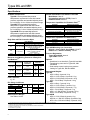
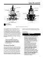
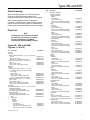
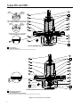
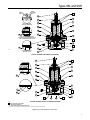
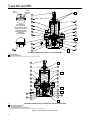
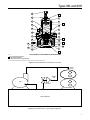
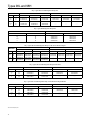
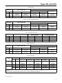
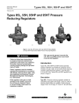
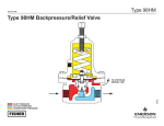
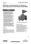
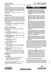
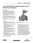
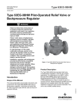
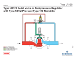
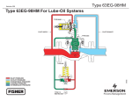
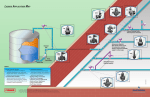
Types 98L and 98H Instruction Manual Form 1570 March 2014 Types 98L and 98H Backpressure Regulators and Relief Valves ! Warning Failure to follow these instructions or to properly install and maintain this equipment could result in an explosion, fire and/or chemical contamination causing property damage and personal injury or death. Fisher® backpressure regulators and relief valves must be installed, operated and maintained in accordance with federal, state and local codes, rules and regulations, and Emerson Process Management Regulator Technologies, Inc. instructions. W6155 TYPE 98H or 98HM If a leak develops or if the outlet continually vents gas, service to the unit may be required. Failure to correct trouble could result in a hazardous condition. Only a qualified person must install or service the unit. Introduction Scope of the Manual This manual provides instructions for the installation, adjustment, maintenance and parts ordering information of Types 98L and 98H Backpressure Regulators and Relief Valves. Instructions and parts lists for other equipment mentioned in this instruction manual are found in separate manuals. W6156 TYPE 98L Figure 1. Types 98L and 98H Backpressure Regulators and Relief Valves Description Types 98L and 98H are direct-operated, spring-loaded backpressure regulators or relief valves. Typical applications include use in wash tanks, small heaters, fuel and oil lines, air supply systems, test fixtures and sterilizers. Relief pressure ranges are 2 to 38 psig / 0.14 to 2.6 bar, in four ranges, for Type 98L and 15 to 200 psig / 1.0 to 13.8 bar, in four ranges for each sizes, for Type 98H. Type 98L is available on body sizes NPS 1/4, 1/2, 3/4 and 1 / DN 15, 20 and 25 and Type 98H on body sizes NPS 1/4, 1/2, 3/4, 1, 1-1/2 and 2 / DN 15, 20, 25, 40 and 50. www.fisherregulators.com D100258X012 Installation, operation and maintenance procedures performed by unqualified personnel may result in improper adjustment and unsafe operation. Either condition may result in equipment damage or personal injury. Use qualified personnel when installing, operating and maintaining the Types 98L and 98H backpressure regulators and relief valves. Types 98L and 98H Specifications Available Constructions Type 98L: Direct-operated low-pressure backpressure regulator/relief valve with internal pressure registration and standard adjusting screw for 2 to 38 psig / 0.14 to 2.6 bar set pressure range Type 98H: Direct-operated high-pressure backpressure regulator/relief valve with internal pressure registration and standard adjusting screw for 5 to 200 psig / 0.34 to 13.8 bar set pressure range Type 98HM: Direct-operated high-pressure backpressure regulator/relief valve with external pressure registration and standard adjusting screw for 5 to 275 psig / 0.34 to 19.0 bar set pressure range Body Sizes and End Connection Styles type 98L 98H 98HM body material Cast Iron WCC Steel, CF8M Stainless steel 1/4 through 1 NPT, NPS 1/2 through 1 / 1/4, 1/2, 3/4, 1 NPT DN 15 through 25, SWE, CL150 RF, CL300 RF, PN16/25/40 RF 1/4 through 2 NPT, 1/4, 1/2, 3/4, 1, NPS 1/2 through 2 / DN 15 through 50, 1-1/2, 2 NPT SWE, CL150 RF, CL300 RF, PN 16/25/40 RF ---1/2, 3/4, 1, 1-1/2, 2 NPT Maximum Cold Working Pressures of Body Size and Materials(1)(2) regulator body size Type 98L All Sizes Type 98H All Sizes Type 98HM All Sizes Body and Spring case materials Cast Iron Steel Stainless Steel Cast Iron Steel Stainless Steel Steel Stainless Steel maximum inlet pressure(3) psig bar 60 4.1 125 8.6 125 8.6 300 20.7 300 20.7 300 20.7 300 20.7 300 20.7 Flow Coefficient C1: 35 IEC Sizing Coefficients Body size nps dn 1/4 ---1/2 15 3/4 and 1 20 and 25 1-1/2 and 2 40 and 50 Xt 0.78 Relief Pressure Ranges See Tables 1 and 2 Fd fl Km 0.50 0.91 0.83 0.88 0.92 0.83 0.69 0.77 0.85 Shutoff Classification Per ANSI/FCI 70-3-2004 Metal Seats: Class IV Polytetrafluoroethylene (PTFE): Class IV Elastomer Seats: Class VI Temperature Capabilities for Elastomer Parts(1)(4) material Nitrile (NBR) Neoprene (CR) Fluorocarbon (FKM)(5) Ethylenepropylene (EPDM)(5) Perfluoroelastomer (FFKM)(5) PTFE Diaphragm protector Temperature Capabilities for Metal Parts(1)(4) material Cast iron(6) WCC Steel CF8M Stainless steel temperature range -40 to 406°F / -40 to 207°C -20 to 450°F / -29 to 232°C -40 to 450°F / -40 to 232°C Type 98HM Sensing Line Connection NPS 1/2, 1-1/2 or 2 / DN 15, 40 or 50 Body: 1/8 NPT NPS 3/4 or 1 / DN 20 or 25 Body: 1/4 NPT Pressure Registration Types 98L and 98H: Internal Type 98HM: External Options • Handwheel or tee handle for Types 98L and 98H • Tapped spring case vent for Types 98L, 98H and 98HM • Seal washer to permit spring case pressure loading for Types 98L, 98H and 98HM Approximate Weights Type 98L NPS 1/4 Body: 6 pounds / 3 kg NPS 1/2 / DN 15 Body: 13 pounds / 6 kg NPS 3/4 / DN 20 Body: 30 pounds / 14 kg NPS 1 / DN 25 Body: 30 pounds / 14 kg Type 98H NPS 1/4 Body: 7 pounds / 4 kg NPS 1/2 / DN 15 Body: 7 pounds / 2 kg NPS 3/4 / DN 20 Body: 16 pounds / 7 kg NPS 1 / DN 25 Body: 16 pounds / 7 kg NPS 1-1/2 / DN 40 Body: 55 pounds / 25 kg NPS 2 / DN 50 Body: 55 pounds / 25 kg Type 98HM NPS 1/2 / DN 15 Body: 8 pounds / 4 kg NPS 3/4 or 1 / DN 20 or 25 Body: 20 pounds / 9 kg NPS 1-1/2 or 2 / DN 40 or 50 Body: 73 pounds / 33 kg 1. The pressure/temperature limits in this instruction manual or any applicable standard limitation should not be exceeded. 2. Temperature and/or the body end connection may decrease these maximum pressures. 3. Maximum inlet pressure equals set pressure plus buildup. 4. Pressure and/or the body end connection may decrease these maximum temperatures. 5. Not for use on steam service. 6. Not available for Type 98HM. 2 temperature range -40 to 180°F / -40 to 82°C -40 to 180°F / -40 to 82°C 0 to 300°F / -18 to 149°C Limited to 200°F / 93°C for hot water -40 to 275°F / -40 to 135°C 0 to 425°F / -18 to 218°C -40 to 400°F / -40 to 207°C Types 98L and 98HType 98HM October 2008 Type 98HM Backpressure/Relief Valve control spring control spring REGISTRATION HOLE Elastomer Diaphragm Elastomer DIAPHRAGM VALVE PLUG C OMP VALVE PLUG to upstream TO UPSTREAM Sensing line SENSING LINE O-ring SEAT A6925 m1155 INLET PRESSURE OUTLET PRESSURE ATMOSPHERIC PRESSURE orifice orifice type 98H (Also typical of type 98L) type 98HM Inlet pressure outlet pressure atmospheric pressure Figure 2. 98 Series Operational Schematics The Type 98HM can be used for backpressure or relief applications in liquid, gas or steam service. The Type 98HM features a sensing line connection for sensing pressure externally from the regulator. The Type 98HM is a direct-operated, spring-to-close regulator and requires no external power to operate. A seal washer for the set screw can be included when applications require pressure loading of the spring case (not available on NPS 1-1/2 and 2 / DN 40 and 50 bodies). Note Using a Type 98HM as a relief valve does not exclude the installation of an ASME certified full flow relief valve as specified by local codes and regulations or system design. Principle of Operation Relief or backpressure valves respond to changes in upstream pressure. Pressure changes register under the diaphragm (see Figure 2) through a registration hole in the valve body (through upstream sensing line connection for Type 98HM). When the pressure increases beyond the spring setting, the diaphragm pressure overcomes the spring compression. This causes the valve plug to move away from the orifice. The flow line through the valve is open and excess pressure is vented. When upstream pressure drops back to normal, the valve resumes its closed position. Installation ! Warning Personal injury or system damage may result if this relief valve/backpressure regulator is installed where service conditions could exceed the limits given on the Specifications section or regulator nameplate. Installations should be adequately protected from physical damage. Overpressuring any portion of this equipment may cause equipment damage, leaks in the relief valve/ backpressure regulator, or personal injury due to bursting of pressurecontaining parts. System operation within the limits shown in the Specifications section (page 2) does not eliminate the possibility of damage from external sources or debris in the pipeline. The relief valve/backpressure regulator should be inspected for damage regularly and after any overpressure condition. 3 Types 98L and 98H Table 1. Types 98L and 98H Relief Set Pressure Ranges BODY SIZES NPS TYPE 98L RELIEF SET PRESSURE RANGE(1) TYPE 98H RELIEF SET PRESSURE RANGE(1) SPRING COLOR SPRING PART NUMBER SPRING WIRE DIAMETER SPRING FREE LENGTH DN psig bar psig bar Inch mm Inch mm 1/4 ---- 2 to 7 6 to 14 12 to 25 20 to 38 0.14 to 0.48 0.41 to 0.97 0.83 to 1.7 1.4 to 2.6 15 to 35 25 to 75 70 to 140 130 to 200 1.0 to 2.4 1.7 to 5.2 4.8 to 9.6 9.0 to 13.8 Yellow Green Red Blue 1E392527022 1E392627012 1E392727142 1L346127142 0.148 0.170 0.207 0.225 3.76 4.32 5.26 5.72 2.00 2.00 1.93 2.08 50.8 50.8 49.0 52.8 1/2 15 2 to 7 6 to 14 12 to 25 20 to 38 0.14 to 0.48 0.41 to 0.97 0.83 to 1.7 1.4 to 2.6 15 to 35 25 to 75 70 to 140 130 to 200 1.0 to 2.4 1.7 to 5.2 4.8 to 9.6 9.0 to 13.8 Yellow Green Red Blue 1E395627022 1D7455T0012 1E395727192 1L380027142 0.207 0.234 0.281 0.331 5.26 5.94 7.14 8.41 2.50 1.02 2.44 2.25 63.5 25.9 62.0 57.2 3/4 and 1 20 and 25 2 to 7 6 to 14 12 to 25 20 to 38 0.14 to 0.48 0.41 to 0.97 0.83 to 1.7 1.4 to 2.6 15 to 35 25 to 75 70 to 140 130 to 200 1.0 to 2.4 1.7 to 5.2 4.8 to 9.6 9.0 to 13.8 Yellow Green Red Blue 1E398927022 1E399027142 1E399127162 1L380127082 0.306 0.343 0.406 0.468 7.77 8.71 10.3 11.9 4.00 4.00 4.00 3.75 102 102 102 95.3 1-1/2 and 2 40 and 50 ------------- ------------- 5 to 35 20 to 65 50 to 100 80 to 170 0.3 to 2.4 1.4 to 4.5 3.5 to 6.9 5.5 to 11.7 Dark Gray Light Blue Light Gray Black 1E792327092 1E795327082 1E795427082 1P788827082 0.468 0.531 0.562 0.625 11.9 13.5 14.2 15.9 6.56 6.56 6.56 6.56 167 167 167 167 1. All springs may be backed off to 0 psig / 0 bar. However, highest capacities and best performances are obtained by using these springs in their recommended ranges. Table 2. Type 98HM Relief Set Pressure Ranges SPRING MATERIAL Steel Stainless steel BODY SIZES SPRING RANGE(1) DN psig bar SPRING COLOR SPRING PART NUMBER 1/2 15 15 to 35 25 to 75 70 to 140 130 to 200 1.0 to 2.4 1.7 to 5.2 4.8 to 9.6 9.0 to 13.8 Yellow Green Red Blue 3/4 and 1 20 and 25 15 to 35 25 to 75 70 to 140 130 to 200 1.0 to 2.4 1.7 to 5.2 4.8 to 9.6 9.0 to 13.8 1-1/2 and 2 40 and 50 5 to 35 20 to 65 50 to 100 80 to 170 1/2 15 3/4 and 1 20 and 25 NPS SPRING WIRE DIAMETER SPRING FREE LENGTH Inch mm Inch mm 1E395627022 1D7455T0012 1E395727192 1L380027142 0.207 0.234 0.281 0.331 5.26 5.94 7.14 8.41 2.50 2.62 2.44 2.25 63.5 66.5 62.0 57.2 Yellow Green Red Blue 1E398927022 1E399027142 1E399127162 1L380127082 0.306 0.343 0.406 0.468 7.77 8.71 10.3 11.9 4.00 4.00 4.00 3.75 102 102 102 95.3 0.34 to 2.4 1.4 to 4.5 3.5 to 6.9 5.5 to 11.7 Dark Gray Light Blue Light Gray Black 1E792327092 1E795327082 1E795427082 1P788827082 0.469 0.531 0.563 0.656 11.9 13.5 14.3 16.7 6.50 6.50 6.50 6.50 165 165 165 165 15 to 100 100 to 275 1.0 to 6.9 6.9 to 19.0 Unpainted Unpainted 14B9943X012 14B9942X022 0.282 0.375 7.16 9.53 2.50 2.50 63.5 63.5 15 to 100 100 to 275 1.0 to 6.9 6.9 to 19.0 Unpainted Unpainted 14B9944X022 14B9945X022 0.432 0.562 11.0 14.2 4.03 4.03 102 102 1. All springs may be backed off to 0 psig / 0 bar. However, highest capacities and best performances are obtained by using these springs in their recommended ranges. Table 3. Torque Specifications Body SizEs SPRING CASE DN FOOT-POUNDS N•m FOOT-POUNDS N•m 1/4 1/2 3/4, 1 1-1/2, 2 ---15 20, 25 40, 50 4.5 to 5.0 10 to 13 24 to 30 40 to 50 6,1 to 6,8 14 to 18 33 to 41 54 to 68 8 to 12 29 to 35 33 to 42 140 to 170 11 to 16 39 to 47 45 to 57 190 to 230 Unbox and inspect the valve. Remove pipe scale and other foreign material from the connecting pipeline. Apply a suitable pipe compound to the external threads. The relief valve can be installed in any position as long as the flow is in the direction indicated by the arrow cast on the body. Overpressure Protection ! Warning Overpressuring any portion of this equipment may result in equipment damage, leaks in the relief valve / 4 ORIFICE NPS backpressure regulator, or personal injury due to bursting of pressure-containing parts. The system should be inspected after any overpressure condition. Relief or backpressure ranges are from 2 to 200 psig / 0.14 to 13.8 bar. The individual spring range of your relief valve is stamped on the nameplate. Maximum inlet pressures depend upon body materials and temperatures. See the Specifications section for the maximum inlet pressure of the valve. The valve should be inspected for damage after any overpressure condition. Types 98L and 98H Vents ! Warning If using a Type 98L, 98H or 98HM Backpressure Regulator or Relief Valve on hazardous or flammable gas service, personal injury and property damage could occur due to fire or explosion of vented gas that may have accumulated. To prevent such injury or damage, provide piping or tubing to vent the gas to a safe, well-ventilated area. Also, when venting a hazardous gas, the piping or tubing should be located far enough away from any buildings or windows so to not create a further hazard, and the vent opening should be protected against anything that could clog it. If remote venting is necessary, an optional tapped vent in the spring case is available. Install remote vent lines in the spring case and outlet openings. The vent lines must have the largest practical diameter and be as short as possible with a minimum number of bends or elbows. Startup Key numbers are shown in Figures 3 through 5. With proper installation completed and system equipment properly adjusted, close any vent valves, and slowly open the upstream shutoff valve while using pressure gauges to monitor pressure. If set pressure adjustment is necessary, monitor the inlet pressure with a gauge during the adjustment procedure. Adjustment Each unit is factory set for the pressure specified on your order. The allowable spring range is stamped on the nameplate. If a pressure setting beyond the indicated range is required, replace with the appropriate spring. Be sure to label the valve to indicate the new pressure range. Always use a pressure gauge to monitor pressure when making adjustments. All regulator springs can be backed off to 0 psig / 0 bar. Recommended set pressure ranges available, maximum inlet pressures and temperatures, and color codes of the respective springs are shown in the Specifications section and Tables 1 and 2. Loosen the jam nut (key 17). To increase the setting, turn the adjusting screw (key 15) clockwise. Turn the adjusting screw counterclockwise to decrease the setting. Tighten the jam nut. Shutdown Close the upstream shutoff valve, and release all pressure from the backpressure regulator/relief valve. Maintenance ! Warning To avoid personal injury and equipment damage, isolate the valve from all pressure. Cautiously release pressure from the valve before attempting disassembly. Due to normal wear and damage that may occur from external sources, relief valve parts such as the O-rings, gaskets, diaphragm, orifice and valve plug should be inspected periodically and replaced as necessary. The frequency of inspection and replacement depends upon the severity of service conditions or the requirements of state and federal laws. Instructions are given below for disassembly of the Types 98L and 98H backpressure regulators/relief valves. These valves do not have to be removed from the pipeline to inspect internal parts. Suitable lubricants are indicated on the assembly drawings. Apply the lubricants as the relief valve is being reassembled. Refer to Figures 3, 4 and 5 while servicing the relief valve. caution Metal diaphragms have thin sharp edges. To avoid hand cuts, use caution when handling the diaphragm and particularly the diaphragm edge. Type 98 relief valves contain or may contain a thin metal diaphragm. Use care when handling the metal diaphragms to prevent hand injuries or damage to the diaphragm. 1. Relieve the spring tension by loosening the jam nut (key 17) and turning the adjusting screw (key 15) counterclockwise. Remove the cap screws (key 16). Lift off the spring case (key 2), upper spring seat (key 9) and spring (key 11). 2. Lift out the diaphragm unit which includes the pusher post (key 6), lower spring seat (key 8), diaphragm 5 Types 98L and 98H head (key 25, Type 98L), washer (key 7), valve plug (key 4) and diaphragm (key 12). There will be two diaphragms if the diaphragm material is metal or fluorocarbon (FKM) except for Type 98L, NPS 1/4, 2 to 7 psi / 0.14 to 0.48 bar range which uses only one metal diaphragm. For Type 98HM, two diaphragms are also required if material used is Ethylenepropylene (EPDM) except for NPS 3/4 or 1 / DN 20 or 25 which uses only one Ethylenepropylene (EPDM) diaphragm. Refer to Figures 3, 4 and 5 for the diaphragm and gasket assembly. 3. Check the orifice (key 3). If it needs replacing or repairing, unscrew the valve plug guide (key 5) and then the orifice. The valve plug can be removed by sliding it off of the pusher post (key 6). Note If damage to elastomer or metal seating surfaces is severe, replace the orifice (key 3) and valve plug O-ring (key 22) with new parts. However, by following the lapping procedure below, it is possible to repair metal seating surfaces if they are only slightly worn or scratched. 4. Lapping procedure: a. Place a small amount of 500-grit silicon carbide or aluminum oxide lapping compound on a flat surface such as a piece of heavy plate glass. b. Take the valve plug (key 4) or orifice (key 3) and move it in a figure 8 motion on the lapping compound. Do not allow the part to tip or rock since this would round the corners. c. Repeat step b for each part, using an 800-grit or 1000-grit silicon carbide or aluminum oxide lapping compound. d. Wash away all traces of the lapping compound. To help prevent scratching the seating surfaces, a light coat of oil may be applied before returning the valve plug and orifice to the body (key 1). See Table 3 for torque specifications. 5. Return the orifice and valve plug guide (key 5) to the body. 6. Place a small amout of sealant on the threads before installing the valve plug guide and the orifice. See Table 3 for torque specifications. 7. To replace the valve plug O-ring (key 22), remove the screw (key 24) and O-ring retainer (key 21) from the plug. Remove and replace the O-ring. 6 8. Separate the remainder of the diaphragm unit parts. Take the locknut (key 26) off of the pusher post (key 6). Slide off the lock washer (key 23), lower spring seat, diaphragm head (Type 98L), diaphragm, washer (key 7) and gasket (key 10). 9. Slip the plug (key 4) onto the pusher post. Place a gasket (key 10) on the shaft of the pusher post (key 6) over the threaded portion until it rests on the base of the post. If elastomer diaphragm is used, place a metal washer (key 7) on top of the gasket. For Type 98H, NPS 1-1/2 to 2 / DN 40 to 50) with metal diaphragm, place another gasket on the shaft of the pusher post until it rests on the bottom diaphragm head (key 25), see Figure 4. Refer to Figures 3 to 5. Note If a metal diaphragm is to be replaced by an elastomer diaphragm or an elastomer diaphragm by a metal diaphragm, a new pusher post is required. Each diaphragm material requires a different pusher post length and make sure the proper number of metal or elastomer diaphragm that will be used is followed. Refer to the Parts List section for the correct number of diaphragm to be used. 10. For the metal diaphragms, replace the large diaphragm gasket (key 19) on the surface of the body (key 1) that will support the diaphragms. There will be two diaphragms used per regulator, except for Type 98L, NPS 1/4 with 2 to 7 psi / 0.14 to 0.48 bar set pressure range which uses only one metal diaphragm. The raised surfaces of the metal diaphragms should be placed in the unit so that they are facing toward the assembler (toward the spring) except only when one diaphragm is being used then the raised surface should be facing down (towards the body). See Figures 3 to 5 as references. 11. Slip the lower spring seat (key 8) and lock washer (key 23) back onto the pusher post. Screw on the locknut (key 26) and return the diaphragm unit to the body (key 1). 12. Set the spring (key 11) in the lower spring seat and place the upper spring seat (key 9) on the spring. 13. Put the spring case (key 2) over the spring and onto the body. Tighten the cap screws (key 16) finger tight only. 14. To ensure proper slack in the diaphragm, apply some spring compression by turning the adjusting screw clockwise. Finish tightening the cap screws. Types 98L and 98H Parts Ordering Key Description When corresponding with your local Sales Office about this equipment, always reference the equipment serial number stamped on the nameplate. When ordering replacement parts, specify the complete 11-character part number of each required part as found in the following parts list. Separate kits containing all recommended spare parts are available. Parts List Note In this parts list, parts marked NACE are intended for corrosion-resistant service as detailed in the NACE International standard MR0175-2003. Types 98L, 98H and 98HM (Figures 3, 4 and 5) Key Description Part Number Type 98L Parts Kits Elastomer Trim (include keys 3, 4, 10, 12, 21, 22 and 24) NPS 1/4 R98LX000012 NPS 1/2 / DN 15 body R98LX000022 NPS 3/4 and 1 / DN 20 and 25 bodies R98LX000032 Metal Trim (include keys 3, 4, 10, 12 and 19) NPS 1/4 R98LX000042 NPS 1/2 / DN 15 body R98LX000052 NPS 3/4 and 1 / DN 20 and 25 bodies R98LX000062 Type 98H Parts kit Elastomer Trim (include keys 3, 4, 10, 12 and 14 (for NPS 1-1/2 and 2 / DN 40 and 50 only), 21, 22 and 24) NPS 1/4 body R98HX000012 NPS 1/2 / DN 15 body R98HX000022 NPS 3/4 and 1 / DN 20 and 25 bodies R98HX000032 NPS 1-1/2 and 2 / DN 40 and 50 bodies R98HX000072 Metal Trim (include keys 3, 4, 10, 12 and 19) NPS 1/4 body R98HX000042 NPS 1/2 / DN 15 body R98HX000052 NPS 3/4 and 1 / DN 20 and 25 bodies R98HX000062 NPS 1-1/2 and 2 / DN 40 and 50 bodies R98HX000082 Type 98HM Parts Kits (include keys 3, 4, 10, 12, 19, 21, 22, 24 and 53) 416 Stainless steel trim With Fluorocarbon (FKM) O-rings R98HMX00012 With Ethylenepropylene (EPDM) O-rings R98HMXEPR12 316 Stainless steel With Fluorocarbon (FKM) O-rings R98HMX00022 With Ethylenepropylene (EPDM) O-rings R98HMXEPR22 1 Body See following table 2 Spring Case Type 98H Cast iron Standard NPS 1/4 body 2E391219012 NPS 1/2 / DN 15 body 2J496219012 NPS 3/4 and 1 / DN 20 and 25 bodies 3E397819012 NPS 1-1/2 and 2 / DN 40 and 50 bodies ----------- 2 Spring Case (continued) Type 98H (continued) Cast iron (continued) Tapped NPS 1/4 body NPS 1/2 / DN 15 body NPS 3/4 and 1 / DN 20 and 25 bodies NPS 1-1/2 and 2 / DN 40 and 50 bodies Steel Standard NPS 1/4 body NPS 1/2 / DN 15 body NPS 3/4 and 1 / DN 20 and 25 bodies NPS 1-1/2 and 2 / DN 40 and 50 bodies Tapped NPS 1/4 body NPS 1/2 / DN 15 body NPS 3/4 and 1 / DN 20 and 25 bodies NPS 1-1/2 and 2 / DN 40 and 50 bodies 316 Stainless steel Standard NPS 1/4 body NPS 1/2 / DN 15 body NPS 3/4 and 1 / DN 20 and 25 bodies NPS 1-1/2 and 2 / DN 40 and 50 bodies Tapped NPS 1/4 body NPS 1/2 / DN 15 body NPS 3/4 and 1 / DN 20 and 25 bodies NPS 1-1/2 and 2 / DN 40 and 50 bodies Type 98L Cast iron Standard NPS 1/4 body NPS 1/2 / DN 15 body NPS 3/4 and 1 / DN 20 and 25 bodies Tapped NPS 1/4 body NPS 1/2 / DN 15 body NPS 3/4 and 1 / DN 20 and 25 bodies Steel Standard NPS 1/4 body NPS 1/2 / DN 15 body NPS 3/4 and 1 / DN 20 and 25 bodies Tapped NPS 1/4 body NPS 1/2 / DN 15 body NPS 3/4 and 1 / DN 20 and 25 bodies 316 Stainless steel Standard NPS 1/4 body NPS 1/2 / DN 15 body NPS 3/4 and 1 / DN 20 and 25 bodies Tapped NPS 1/4 body NPS 1/2 / DN 15 body NPS 3/4 and 1 / DN 20 and 25 bodies Type 98HM Steel NPS 1/2 / DN 15 body NPS 3/4 and 1 / DN 20 and 25 bodies NPS 1-1/2 and 2 / DN 40 and 50 bodies Stainless Steel NPS 1/2 / DN 15 body NPS 3/4 and 1 / DN 20 and 25 bodies NPS 1-1/2 and 2 / DN 40 and 50 bodies Part Number 2L442919012 ----------3L460819012 4P784019012 2J127522012 2L416322012 3E408722012 ----------2L443022012 2L442022012 3L460722012 3P790422012 2J1275X0012 2L416333092 3E4087X0012 ----------2L4430X0012 2L4420X0012 3L4607X0022 3P7904X0012 2E391319012 3J496319012 4E397919012 ----------3L442119012 4L461019012 2J127922012 3L416122012 4E592922012 ----------3L442222012 4L460922012 2J1279X0022 3L4161X0022 4E592933092 2L4428X0012 3L4422X0012 4L4609X0032 2L442022012 3L460722012 3P790422012 2L4420X0012 3L4607X0022 3P7904X0012 *Recommended spare part. 7 Types 98L and 98H 17 METAL DIAPHRAGMS (KEY 12) SPRING (KEY 11) DIAPHRAGM GASKET (KEY 19) Type 98L except for NPS 1/4, 2 to 7 psi / 0.14 to 0.48 bar range with two metal diaphragms METAL DIAPHRAGM (KEY 12) SPRING (KEY 11) DIAPHRAGM GASKET (KEY 19) 15 L 9 11 26 2 23 8 25 5 12 16 Type 98L (NPS 1/4, 2 to 7 psi / 0.14 to 0.48 bar Range) with one metal diaphragm 1 19 4 10 6 3 L 30A7027 TYPE 98L ASSEMBLY WITH METAL DIAPHRAGM - Apply Lubricant(1) L = anti-seize compound 1. Lubricants must be selected such that they meet the temperature requirements. 17 15 L 9 11 2 7 10 23 8 25 5 16 24 4 12 6 S 21 30A7028 TYPE 98L ASSEMBLY WITH Elastomer DIAPHRAGM - Apply lubricant or sealant(1) L = anti-seize compound S = Multi-Purpose PTFE Thread Sealant 1. Lubricants and sealants must be selected such that they meet the temperature requirements. Figure 3. Type 98L Relief Valve Assemblies 8 26 22 3 L 1 Types 98L and 98H METAL DIAPHRAGMS (KEY 12) SPRING (KEY 11) L 15 DIAPHRAGM GASKET (KEY 19) 9 17 2 11 For Type 98H with 2 metal diaphragms 23 26 16 8 12 10 19 For Type 98H, NPS 1-1/2 and 2 / DN 40 and 50 WITH 2 GASKETS (KEY 10) AND 2 DIAPHRAGM HEADS (KEY 25) L 5 6 10 30A7029 L 4 For Type 98H, NPS 1/4 through 1 / DN 25 1 3 Type 98H Assembly with Metal Diaphragm L 15 9 17 2 11 23 26 14 16 8 12 5 6 7 10 L 4 22 3 L 30A7030 21 24 S 1 Type 98H Assembly with Elastomer Diaphragm - Apply lubricant or sealant(1) L = anti-seize compound S = Multi-Purpose PTFE Thread Sealant 1. Lubricants and sealants must be selected such that they meet the temperature requirements. Figure 4. Type 98H Relief Valve Assemblies 9 Types 98L and 98H METAL DIAPHRAGMS (KEY 12) SPRING (KEY 11) L 15 17 DIAPHRAGM GASKET (KEY 19) 9 11 Type 98HM with 2 metal diaphragms 2 54 For Type 98HM with 2 metal diaphragms, assemble DIAPHRAGM gaskets and metal diaphragms alternately (as shown above) 26 23 16 8 12 19 L 53 6 5 4 10 L 3 TYPE 98hm ASSEMBLY WITH METAL seat and DIAPHRAGM 37B4753 - Apply Lubricant L = Anti-Seize Compound 1. Lubricants must be selected such that they meet the temperature requirements. (1) 53 21 37B4754 15 L 17 2 11 9 54 23 26 8 16 12 19 6 10 5 22 4 1 3 L S 24 L TYPE 98hm ASSEMBLY WITH Elastomer Seat and METal DIAPHRAGM - Apply lubricant or sealant L = anti-seize compound S = Multi-Purpose PTFE Thread Sealant 1. Lubricants and sealants must be selected such that they meet the temperature requirements. (1) Figure 5. Type 98HM Relief Valve Assemblies 10 L 1 Types 98L and 98H 15 L 17 2 11 9 54 23 26 8 16 12 7 6 10 53 21 L 5 22 4 1 3 L S 24 L Type 98HM with Elastomer Seat and Diaphragm 39B3360 - Apply lubricant or sealant L = anti-seize compound S = Multi-Purpose PTFE Thread Sealant 1. Lubricants and sealants must be selected such that they meet the temperature requirements. (1) Figure 5. Type 98HM Relief Valve Assemblies (continued) LUBE OIL COOLER SENSING LINE PUMP TYPE 98HM LUBE OIL RESERVOIR Figure 6. Type 98HM Used in a Typical Bypass Application 11 Types 98L and 98H Key Description Part Number 3* Orifice See following table 4* Valve Plug See following table 5 Valve Plug Guide Types 98L and 98H 416 Stainless steel NPS 1/4 body 1L345835132 NPS 1/2 / DN 15 body 1L341635132 NPS 3/4 and 1 / DN 20 and 25 bodies 1L342935132 NPS 1-1/2 and 2 / DN 40 and 50 bodies 1P788535132 316 Stainless steel NPS 1/4 body, NACE 1L345835072 NPS 1/2 / DN 15 body, NACE 1L3416X0102 NPS 3/4 and 1 / DN 20 and 25 bodies, NACE 1L342935072 NPS 1-1/2 and 2 / DN 40 and 50 bodies, NACE 1P788535072 Type 98HM NPS 1/2 / DN 15 body Metal Seat and Metal Diaphragm 416 Stainless steel 1L341635132 316 Stainless steel 1L3416X0102 Elastomer Seat and Metal Diaphragm 416 Stainless steel 1L341635132 316 Stainless steel 1L3416X0102 Elastomer Seat and Elastomer Diaphragm 416 Stainless steel 1L341635032 316 Stainless steel 1L3416X0102 NPS 3/4 and 1 / DN 20 and 25 bodies 416 Stainless steel 18B5256X012 316 Stainless steel 18B5256X022 NPS 1-1/2 and 2 / DN 40 and 50 bodies 416 Stainless steel 18B3529X012 316 Stainless steel 18B3529X022 6 Pusher Post See following table 7 Washer (Elastomer diaphragm only) 416 Stainless steel trim NPS 1/4 body 1L344736012 NPS 1/2 / DN 15 body 1L339836012 NPS 3/4 and 1 / DN 20 and 25 bodies 1L342836012 316 Stainless steel trim NPS 1/4 body, Standard 1L344736142 NPS 1/4 body, NACE 1L3447X0012 NPS 1/2 / DN 15 body, Standard 1L339835072 NPS 1/2 / DN 15 body, NACE 1L339840032 NPS 3/4 and 1 / DN 20 and 25 bodies, Standard 1L342836142 NPS 3/4 and 1 / DN 20 and 25 bodies, NACE 1L3428X0022 8 Lower Spring Seat NPS 1/4 body, Aluminum 1L344609012 NPS 1/2 / DN 15 body, Aluminum 1L339708012 NPS 1/2 / DN 15 body, Plated Steel (For Type 98HM only with Stainless steel Spring) 17B4480X012 NPS 3/4 and 1 / DN 20 and 25 bodies, Aluminum 1L342708012 NPS 3/4 and 1 / DN 20 and 25 bodies, Plated Steel (For Type 98HM only with Stainless steel Spring) 17B3088X022 NPS 1-1/2 and 2 / DN 40 and 50 bodies, Steel plated 1P787724152 9 Upper Spring Seat, Steel plated NPS 1/4 body 1B798525062 NPS 1/2 / DN 15 body 1D667125072 NPS 1/2 / DN 15 body (For Type 98HM only with SST Spring) 14B9951X012 NPS 3/4 and 1 / DN 20 and 25 bodies 1E398725072 NPS 3/4 and 1 / DN 20 and 25 bodies (For Type 98HM only with SST Spring) 14B9952X012 NPS 1-1/2 and 2 / DN 40 and 50 bodies 1P787624092 10* Gasket Types 95L and 95H, Composition NPS 1/4 body 1L344804022 NPS 1/2 / DN 15 body 1L341104022 NPS 3/4 and 1 / DN 20 and 25 bodies 1L343404022 NPS 1-1/2 and 2 / DN 40 and 50 bodies (2 required, for Type 98H only) 1P788004022 *Recommended spare part. 12 Key Description Part Number 10* Gasket (continued) Type 98HM Graphite NPS 1/2 / DN 15 body 1L3411X0012 NPS 3/4 and 1 / DN 20 and 25 bodies 1L3434X0032 Composition NPS 1/2 / DN 15 body 1L341104022 NPS 3/4 and 1 / DN 20 and 25 bodies 1L343404022 NPS 1-1/2 and 2 / DN 40 and 50 1P788004022 11 Relief Valve Spring See Tables 1 and 2 12* Diaphragm See following table 13 Nameplate, (not shown) ----------14* O-ring, Type 98H only, NPS 1-1/2 and 2 / DN 40 and 50 bodies, Elastomer seat only Nitrile (NBR) 1C782206992 Fluorocarbon (FKM) 1K756106382 Fluorocarbon, NACE 1K756135072 15 Adjusting Screw, Steel plated NPS 1/4 body, (standard) 1C216032992 NPS 1/2 / DN 15 body, (standard) 1D995448702 NPS 1/2 / DN 15 body, For Handwheel 1J496428982 NPS 1/2 / DN 15 body, Type 98HM only (SST Spring) 1D9954X0032 NPS 3/4 and 1 / DN 20 and 25 bodies, (standard) 1A330828982 NPS 3/4 and 1 / DN 20 and 25 bodies, Type 98HM only (SST Spring) 1A3308X0092 NPS 1-1/2 and 2 / DN 40 and 50 bodies, (standard) 1A680128992 16 Cap Screw Zinc-plated steel Type 98L NPS 1/4 body (10 required) 1A407824052 NPS 1/2 / DN 15 body (10 required) 1A381624052 NPS 3/4 and 1 / DN 20 and 25 bodies (12 required) 1A336924052 Types 98H and 98HM NPS 1/4 body (not available to Type 98HM) (6 required) 1A391724052 NPS 1/2 / DN 15 body (8 required) 1A352624052 NPS 3/4 and 1 / DN 20 and 25 bodies (8 required) 1A341824052 NPS 1-1/2 and 2 / DN 40 and 50 bodies (8 required) 1K568428982 16 Cap Screw (continued) Stainless alloy Type 98L NPS 1/4 body (10 required) 1A4078X0102 NPS 1/2 / DN 15 body (10 required) 1A3816X0152 NPS 3/4 and 1 / DN 20 and 25 bodies (12 required) 1A3369X0112 Type 98H NPS 1/4 body (6 required) 1A3917X0062 NPS 1/2 / DN 15 body (8 required) 1A3526X0142 NPS 3/4 and 1 / DN 20 and 25 bodies (8 required) 1A3418X0332 NPS 1-1/2 and 2 / DN 40 and 50 bodies (8 required) 1K5684X0032 Type 98HM For Steel Springs NPS 1/2 / DN 15 body (8 required) 1A352624052 NPS 3/4 and 1 / DN 20 and 25 (8 required) bodies 1A341824052 NPS 1-1/2 and 2 / DN 40 and 50 (8 required) bodies 1K568428982 For Stainless Springs NPS 1/2 / DN 15 body (8 required) 1A3526X0142 NPS 3/4 and 1 / DN 20 and 25 (8 required) bodies 1A3418X0332 17 Jam Nut, Zinc-plated steel NPS 1/4 body 1A352224122 NPS 1/2 / DN 15 body 1A353724122 NPS 1/2 / DN 15 body, (For Type 98HM only with SST Spring) T1208635442 NPS 3/4 and 1 / DN 20 and 25 bodies 1A319224122 NPS 3/4 and 1 / DN 20 and 25 bodies, (For Type 98HM only with SST Spring) 1A3192K0012 NPS 1-1/2 and 2 / DN 40 and 50 bodies 1A368124112 Types 98L and 98H Key Description Part Number 18 Drive Screw (not shown) (2 required) 1A368228982 19* Diaphragm Gasket, Composition (use with 302 Stainless steel diaphragm) Type 98H NPS 1/4 body 1E393104022 NPS 1/2 / DN 15 body 1E396104022 NPS 3/4 and 1 / DN 20 and 25 bodies 1E399304022 NPS 1-1/2 and 2 / DN 40 and 50 bodies 1P787904022 Type 98L NPS 1/4 body 1E394004022 NPS 1/2 / DN 15 body 1E397004022 NPS 3/4 and 1 / DN 20 and 25 bodies 1E390404022 Type 98HM Composition (2 required) NPS 1/2 / DN 15 body 1E396104022 NPS 3/4 and 1 / DN 20 and 25 bodies 1E399304022 NPS 1-1/2 and 2 / DN 40 and 50 bodies 1P787904022 Graphite (2 required) NPS 1/2 / DN 15 body 1E3961X0012 NPS 3/4 and 1 / DN 20 and 25 bodies 1E3993X0012 20 Diaphragm Protector, PTFE (not shown) Type 98L NPS 1/4 body 11A5132X012 NPS 1/2 / DN 15 body 11A5133X012 NPS 3/4 and 1 / DN 20 and 25 bodies 11A5134X012 Type 98H NPS 1/4 body 11A5135X012 NPS 1/2 / DN 15 body 11A5136X012 NPS 3/4 and 1 / DN 20 and 25 bodies 11A5137X012 NPS 1-1/2 to 2 / DN 40 and 50 bodies 11A5527X012 Type 98HM NPS 1/2 / DN 15 body 11A5136X012 NPS 3/4 and 1 / DN 20 and 25 bodies 11A5137X012 21 O-ring Retainer (Elastomer seat only) NPS 1/4 body 416 Stainless steel 1L346035132 316 Stainless steel, NACE 1L346035072 NPS 1/2 (DN 15) body 416 Stainless steel 1L341535232 316 Stainless steel, NACE 1L341535072 NPS 3/4 and 1 (DN 20 and 25) bodies 416 Stainless steel 1L343035132 316 Stainless steel, NACE 1L343035072 NPS 1-1/2 and 2 (DN 40 and 50) bodies 416 Stainless steel 1P787535132 316 Stainless steel, NACE 1P787535072 22* O-ring Types 98L and 98H, Elastomer seat only NPS 1/4 body Nitrile (NBR) 1C853806992 Fluorocarbon (FKM) 1C8538X0052 NPS 1/2 / DN 15 body Nitrile (NBR) 1D288806992 Fluorocarbon (FKM) 1N530106382 Ethylenepropylene (EPDM) 1D2888X0042 NPS 3/4 and 1 / DN 20 and 25 bodies Nitrile (NBR) 1C782106992 Fluorocarbon (FKM) 1C7821X0072 22* O-ring Type 98HM, Elastomer Seat Only NPS 1/2 / DN 15 body Nitrile (NBR) 1D288806992 Fluorocarbon (FKM) 1N530106382 Ethylenepropylene (EPDM) 1N5301X0022 Perfluoroelastomer (FFKM)1N5301X0012 Type 98HM, Elastomer Seat Only NPS 3/4 and 1 / DN 20 and 25 bodies Nitrile (NBR) 1C7821X0062 Fluorocarbon (FKM) 1C7821X0072 Ethylenepropylene (EPDM) 1C7821X0032 Perfluoroelastomer (FFKM)1C7821X0052 Key Description Part Number 22* O-ring (continued) Type 98HM, Elastomer Seat Only (continued) NPS 1-1/2 and 2 / DN 40 and 50 bodies Nitrile (NBR) 1P787403202 Fluorocarbon (FKM) 1P787406382 Ethylenepropylene (EPDM) 1P7874X0032 Perfluoroelastomer (FFKM)1P7874X0022 22 L-ring, Type 98H only, Elastomer seat only, NPS 1-1/2 and 2 / DN 40 and 50 bodies Nitrile (NBR) 1P787403202 Fluorocarbon (FKM) 1P787406382 23 Lock Washer, Steel NPS 1/4 and 1/2 / DN 15 bodies 1C225628982 NPS 3/4 and 1 / DN 20 and 25 bodies 1H624328992 NPS 1-1/2 and 2 / DN 40 and 50 bodies 1A487828992 24 Machine Screw, Stainless steel, Elastomer seat only NPS 1/4 body, NACE 1L346238992 NPS 1/2 / DN 15 body, NACE 1J4159X0012 NPS 3/4 and 1 / DN 20 and 25 bodies 1L343538992 NPS 3/4 and 1 / DN 20 and 25 bodies, NACE 1L3435X0012 NPS 1-1/2 and 2 / DN 40 and 50 bodies, NACE 1P788638992 25 Diaphragm Head Type 98L, Steel plated NPS 1/4 body 1L345525072 NPS 1/2 / DN 15 body 1L339625072 NPS 3/4 and 1 / DN 20 and 25 bodies 1L342125072 Type 98H, NPS 1-1/2 and 2 / DN 40 and 50 bodies Metal Seat with 416 Stainless steel Trim, Steel/316 Stainless steel (1 of each required) 1P788225012/1P788235072 316 Stainless steel Trim, 316 Stainless steel (2 required) 1P788235072 Steel/316 Stainless steel (1 of each required) 1P788225012/1P788235072 Elastomer Seat with 416 Stainless steel Trim, Steel (2 required) 1P788225012 316 Stainless steel Trim, 316 Stainless steel (2 required) 1P788235072 Type 98HM, NPS 1-1/2 and 2 / DN 40 and 50 bodies (2 required) 1P788235072 26 Locknut, Steel plated NPS 1/4 and 1/2 / DN 15 bodies 1L872324122 NPS 3/4 and 1 / DN 20 and 25 bodies 1L872224122 NPS 1-1/2 and 2 / DN 40 and 50 bodies 1P788724122 27 Tee Handle Assembly (not shown), Types 98L and 98H only NPS 1/4 1F2236000A2 NPS 3/4 and 1 / DN 20 and 25 1F2238000A2 28 Handwheel (not shown), Zinc, NPS 1/2 / DN 15 Types 98L and 98H bodies only 1J496144012 29 Machine Screw (not shown), Steel plated, NPS 1/2 / DN 15 body (with handwheel only) 16A5763X012 30 Lockwasher (not shown), Steel, NPS 1/2 / DN 15 body (with handwheel only) 1A352332992 45* O-ring (not shown) Types 98L and 98H (with sealed adjusting screw only) 1E547706992 50 Sealing Washer (not shown) Types 98L and 98H NPS 1/2 / DN 15 1V205699012 NPS 3/4 and 1 / DN 20 and 25 11A9681X012 Type 98HM NPS 1/2 / DN 15 1V2056X0022 NPS 3/4 and 1 / DN 20 and 25 11A9681X022 *Recommended spare part. 13 Types 98L and 98H Key 1 Types 98L and 98H Regulator Body, NPT body size type 98H type 98L nps dn Cast Iron Steel 316 Stainless Steel Cast Iron Steel 316 Stainless Steel 1/4 1/2 3/4 ---15 20 1L346419012 2L339519012 2L342519012 1L372122012 2L368722012 2L373422012 1L372133092 2L368733092 2L373433092 1L346519012 2L339219012 2L341919012 1L372322012 2L368922012 2L318222012 1L372333092 2L368933092 2L318233092 1 1-1/2 2 25 40 50 2L342619012 3P786819012 3P786719012 2L373522012 3P786822012 3P786722012 2L373533092 3P786833092 3P786733092 2L342019012 ------- 2L318322012 ------- 2L318333092 ------- Key 1 Type 98HM Regulator Body, NPT body size TYPE 98HM NPS DN Steel 316 Stainless Steel 1/2 3/4 1 1-1/2 2 15 20 25 40 50 37B3472X012 48B5252X012 48B6241X012 38B3526X012 38B3526X032 37B3472X022 48B5252X022 48B6241X022 38B3526X022 38B3526X042 Key 1 Types 98L and 98H Regulator Body, CL150 and CL300 RF Flanges type 98H Body Material body size Steel type 98L Body Material Stainless Steel Steel Stainless Steel nps dn CL150 RF CL300 RF CL150 RF CL300 RF CL150 RF CL300 RF CL150 RF CL300 RF 1/2 3/4 1 15 20 25 1V5178X0012 15A6098X022 2V3805X0012 20A4987X0A2 23B9543X022 2U8048X0012 1V5178X0022 15A6098X012 2V3805X00B2 20A4987X012 23B9543X012 2U8048X0022 25A9930X022 2V4264X0022 2V3641X0022 20A4701X012 14B2317X012 2U8047X0012 25A9930X012 2V4264X0012 2V3641X0012 20A4701X022 14B2317X022 2U8047X0062 1-1/2 2 40 50 21B0804X012 10A0192X012 1V4541X0012 10A4986X012 21B0804X022 10A0192X022 1V4541X0022 10A4986X052 ------- ------- ------- ------- Key 1 Types 98L and 98H Regulator Body, Socket Weld body size type 98H Body Material type 98L Body Material nps dn Steel Stainless Steel Steel Stainless Steel 1/2 3/4 1 15 20 25 2L9673X0022 2N443922012 2N414422012 2L9673X0012 2N4439X0012 2N4144X0012 2U8059X0012 2N4463X0012 2N445222012 2U8059X0022 2N4463X0022 2N4452X0012 1-1/2 2 40 50 3V4542X0012 30A0191X012 3V4542X0022 30A0191X032 ------- ------- Key 1 Types 98L and 98H Regulator Body, PN 16/25/40 RF Flanged Bodies body size type 98H Body Material nps dn Steel 316 Stainless Steel Steel 316 Stainless Steel 1/2 3/4 1 15 20 25 14B2236X012 14B2236X032 14B2236X052 14B2236X022 14B2236X042 14B2236X062 24B1959X012 14B2237X012 14B2237X032 24B1959X022 14B2237X022 14B2237X042 1-1/2 2 40 50 14B2236X072 14B1513X012 14B2236X082 14B1513X022 ------- ------- *Recommended spare part. 14 type 98L Body Material Types 98L and 98H Key 3* Orifice body size ELASTOMER SEAT METAL TO METAL SEAT Standard Applications NACE Applications nps dn 416 Stainless Steel 316 Stainless Steel 416 Stainless Steel 316 Stainless Steel 1/4 1/2 3/4, 1 ---15 20, 25 1E391646172 1E395046172 1E398046172 1E391635072 1E395035072 1E398035072 1L345935132 1L341735132 1L343135132 1L345935072 1L341735072 1L343135072 1L345935072 1L341735072 1L343135072 1-1/2, 2 40, 50 2P787046172 2P787035072 1P787135132 1P787135072 1P787135072 Key 4* Types 98L and 98H Valve Plug body sizeS ELASTOMER SEAT METAL TO METAL SEAT Standard Applications NACE Applications nps dn 416 Stainless Steel 316 Stainless Steel 416 Stainless Steel 316 Stainless Steel 1/4 1/2 3/4, 1 ---15 20, 25 1L345246172 1L344146172 1L343746172 1L345235072 1L344135162 1L343735162 1L345135132 1L344335132 1L343635132 1L345135072 1L344335072 1L343635072 1L345135072 1L344335072 1L343635072 1-1/2, 2 40, 50 1P787246172 1P787235072 1P787346172 1P787335072 1P787335072 Key 4* Type 98HM Valve Plug body size nps ELASTOMER SEAT AND METAL DIAPHRAGM METAL SEAT AND METAL DIAPHRAGM ELASTOMER SEAT AND ELASTOMER DIAPHRAGM dn 416 Stainless Steel 316 Stainless Steel 416 Stainless Steel 316 Stainless Steel 416 Stainless steel 316 Stainless Steel 1/2 15 17B3475X012 17B3475X022 17B3474X032 17B3474X012 17B3474X032 17B3474X012 3/4, 1 20, 25 18B5255X012 18B5255X022 18B5254X012 18B5254X022 18B5254X012 18B5254X022 1/2, 2 40, 50 18B3528X012 18B3528X022 18B3530X012 18B3530X022 18B3530X012 18B3530X022 Key 6 Pusher Post body size ELASTOMER SEAT METAL TO METAL SEAT Standard Applications NACE Applications nps dn 416 Stainless Steel 316 Stainless Steel 416 Stainless Steel 316 Stainless Steel 1/4 1/2 ---15 1L345735132 1L344535132 1L345735072 1L344535072 1L345635132 1L344235132 1L345635072 1L344235072 1L345635072 1L344235072 3/4, 1 1-1/2, 2 20, 25 40, 50 1L343935132 1P788335132 1L343935072 1P788335072 1L343835132 1P788435132 1L343835072 1P788435072 1L343835072 1P788435072 Key 12* Diaphragm Body SizeS Type 98L nps Dn Neoprene (cr) Neoprene (CR) with PTFE Protector Fluorocarbon (FKM) (2 required) Ethylenepropylene (EPDM)(3) 302 Stainless Steel (2 required) 1/4 1/2 3/4, 1 ---15 20, 25 1L345302112 1L341302112 1L342302112 ---------- 1L345302402 1L341302402 1L342302402 ---------- 1L345436012(4) 1L341436012 1L342236012 98H 98H and 98HM Diaphragm Material 1/4 ---- 1L344902112 1K344902112 1L344902402 ---- 1L345036012 1/2 15 1L341202112 ---- 1L341202402 1L3412X0032(1) 1L339936012 3/4, 1 1-1/2, 2 20, 25 40, 50 1L343302112 1P788102192 ------- 1L3433X0032 11A1347X012 1L3433X0062 1P7881X0022(2) 1L343236012 1P787836012 1. 1 required for Type 98H and 2 for Type 98HM. 2. 2 required. 3. Available to NPS 1/2 / DN 15 Type 98H and all sizes Type 98HM. Please consult your local Sales Office for Ethylenepropylene (EPDM) option on other sizes. 4. Only 1 metal diaphragm is required for Type 98L, NPS 1/4, 2 to 7 psi / 0.14 to 0.48 bar; 2 metal diaphragms for other ranges. *Recommended spare part. 15 Types 98L and 98H Key Description 51 NACE Tag (not shown) 52 Tag Wire (not shown), NACE 53 O-ring (for Type 98HM only) Nitrile (NBR) (not available with Metal Diaphragms) NPS 1/2 / DN 15 body NPS 3/4 and 1 / DN 20 and 25 bodies NPS 1-1/2 and 2 / DN 40 and 50 bodies Ethylenepropylene (EPDM) NPS 1/2 / DN 15 body NPS 3/4 and 1 / DN 20 and 25 bodies NPS 1-1/2 and 2 / DN 40 and 50 bodies Part Number --------------------- 1H292406992 1D2375X0022 1D262006992 1V8029X0012 1D2375X0042 1D2620X0052 Key Description Part Number 53 O-ring (for Type 98HM only) (continued) Fluorocarbon (FKM) NPS 1/2 / DN 15 body 1R620106382 NPS 3/4 and 1 / DN 20 and 25 bodies 1D237506382 NPS 1-1/2 and 2 / DN 40 and 50 bodies 1D2620X0032 Perfluoroelastomer (FFKM) (not available with Composition Diaphragms) NPS 1/2 / DN 15 body 1V8029X0022 NPS 3/4 and 1 / DN 20 and 25 bodies 1D2375X0052 NPS 1-1/2 and 2 / DN 40 and 50 bodies 1D2620X0082 54 Type Y602-12 (shown in the 98HM Series assemblies) 27A5516X012 *Recommended spare part. Industrial Regulators Natural Gas Technologies TESCOM Emerson Process Management Regulator Technologies, Inc. Emerson Process Management Regulator Technologies, Inc. Emerson Process Management Tescom Corporation USA - Headquarters McKinney, Texas 75070 USA Tel: +1 800 558 5853 Outside U.S. +1 972 548 3574 USA - Headquarters McKinney, Texas 75070 USA Tel: +1 800 558 5853 Outside U.S. +1 972 548 3574 USA - Headquarters Elk River, Minnesota 55330-2445, USA Tels: +1 763 241 3238 +1 800 447 1250 Asia-Pacific Shanghai 201206, China Tel: +86 21 2892 9000 Asia-Pacific Singapore 128461, Singapore Tel: +65 6770 8337 Europe Selmsdorf 23923, Germany Tel: +49 38823 31 287 Europe Bologna 40013, Italy Tel: +39 051 419 0611 Europe Bologna 40013, Italy Tel: +39 051 419 0611 Chartres 28008, France Tel: +33 2 37 33 47 00 Asia-Pacific Shanghai 201206, China Tel: +86 21 2892 9499 Middle East and Africa Dubai, United Arab Emirates Tel: +011 971 4811 8100 Middle East and Africa Dubai, United Arab Emirates Tel: +011 971 4811 8100 For further information visit www.fisherregulators.com The Emerson logo is a trademark and service mark of Emerson Electric Co. All other marks are the property of their prospective owners. Fisher is a mark owned by Fisher Controls International LLC, a business of Emerson Process Management. The contents of this publication are presented for informational purposes only, and while every effort has been made to ensure their accuracy, they are not to be construed as warranties or guarantees, express or implied, regarding the products or services described herein or their use or applicability. We reserve the right to modify or improve the designs or specifications of such products at any time without notice. Emerson Process Management Regulator Technologies, Inc. does not assume responsibility for the selection, use or maintenance of any product. Responsibility for proper selection, use and maintenance of any Emerson Process Management Regulator Technologies, Inc. product remains solely with the purchaser. ©Emerson Process Management Regulator Technologies, Inc., 1965, 2014; All Rights Reserved