1
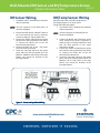
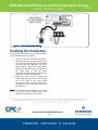
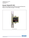
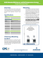
Wall-Mounted RH Sensor and RH/Temperature Sensor
Product Information Sheet
Overview
Mounting
CPC specs a wall-mounted relative humidity (RH)
sensor (P/N 203-5751) and/or RH and temperature
sensor (P/N 203-5752) for use in building control and
anti-sweat control applications using CPC input
boards.
203-5751
1. Insert a screwdriver into the gap in the plastic
on the bottom side of the sensor enclosure,
and pry the front part of the enclosure away
from the rear mounting plate. Pull the front
away from the mounting plate until the top
separates from the mounting plate.
2. Remove the punch outs above the wiring
connectors so that the sensor cables can be
run into the sensor enclosure (see Figure 1).
3. Use the pre-made holes to mount the plate
on a junction box using the screws provided,
or mount it against a wall or riser. Do not
mount the plate upside down or sideways.
The plate should be mounted with the
terminal blocks toward the bottom.
4. If necessary, drill or cut a hole in the wall to
allow the sensor cable to be run through the
wall into the sensor’s terminal block.
Specifications
General
Input Power
12VDC
Enclosure
High-impact plastic, white
Relative Humidity (RH)
Sensing
Digitally profiled thin-film
Element
capacitive
RH Accuracy
±3% RH over the range 20%-90%
RH
Stability
<0.5% RH per year
Operating
0-100% RH
Humidity Range
Analog Output
0-5VDC; 3-wire, observe
polarity
Scaling
0-100% RH
Temperature
Temperature
±0.4°F from 32°F to 140°F
Accuracy
Analog Out
Resistive, 2-wire, no polarity
Choosing a Mounting
Location
Mount the sensor indoors in a central location within
the zone to be measured, away from doors, windows,
vents, heaters, and outside walls that could affect
temperature readings. The sensor should be at least
four feet from the floor, and no higher than necessary
to prevent tampering.
Figure 1 - RH/Temp Sensor Back Plate
29
Wall-Mounted RH Sensor and RH/Temperature Sensor
Product Information Sheet
RH Sensor Wiring
203-5751
RH/Temp Sensor Wiring
1. Use Belden #8771 shielded three-conductor
cable or equivalent.
RH wiring is the same as the RH wiring shown in
the diagram(Figure 2). For temp sensor
wiring, follow the steps below:
1. Use Belden #8761 shielded two-conductor
cable or equivalent.
NOTE: Seat the connector on the back plate if it
becomes dislodged.
NOTE: Seat the connector on the back plate if it
becomes dislodged.
2. Connect the RED, BLACK, and WHITE wires to
the screw terminals the sensor’s connector
as shown in Figure 2. Clip the SHIELD wire.
3. Connect the SHIELD and BLACK wires to the
0V terminal of the input board (under INPUT
1). Connect the WHITE wire to the SIG
terminal of the input board.
4. Connect the RED wire to the +12V power
terminal on the input board.
5. Locate the input dip switch for the sensor
point, and set to the OFF position (LEFT for
MultiFlex, DOWN for 16AI). Refer to the input
board’s user manual for locations of the
input dip switches.
2. Connect the BLACK and CLEAR wires to the
screw terminals the sensor’s connector as
shown in Figure 2. Clip the SHIELD wire. Note
that the third terminal on the sensor
connector is unused.
3. Connect the SHIELD and BLACK wires to the
0V terminal of the input board (under INPUT
2). Connect the CLEAR wire to the SIG
terminal of the input board.
4. Locate the input dip switch for the sensor
point, and set to the ON position (RIGHT for
MultiFlex, UP for 16AI). Refer to the input
board’s user manual for locations of the
input dip switches.
Figure 2 – Sensor and Input Board Wiring
30
Wall-Mounted RH Sensor and RH/Temperature Sensor
Product Information Sheet
203-5751
Figure 3 – Sensor and Input Board Wiring
Finishing the Installation
Once the back plate of the sensor is mounted and the
sensor and board wiring is complete:
1. Attach the sensor circuit board enclosure to
the mounting plate. Push the top of the front
part onto the mounting plate so the hooked
mounting tabs fit underneath the circuit
board enclosure, and push the bottom part
down so that the three prongs on the back of
the circuit board fit into the wiring
connector. Continue pushing until the front
part is flush with the mounting plate.
2. Replace the front cover by inserting the
hooked tab at the top of the cover into the
slot on the front of the circuit board
enclosure so that it snaps into place. Press
the bottom of the cover until it snaps into
the enclosure.
NOTE: Do not expose sensor element to the fumes
of curing RTV silicone rubber. Doing so will
damage the calibration of the element.
EmersonTM, Emerson. Consider It SolvedTM and Emerson Climate TechnologiesTM logos are trademarks and service marks of Emerson Electric Co.
Intelligent StoreTM is a trademark of Emerson Climate Technologies. All other trademarks are the property of their respective owners.
© 2011 Emerson Climate Technologies, Inc. All rights reserved.
31