1
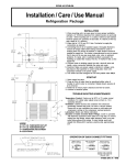
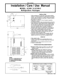
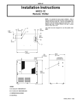
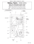
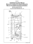
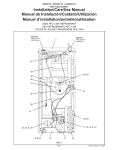
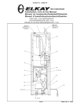
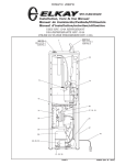
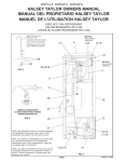
HCR8*1J
Installation Instructions
HCR8-1J Refrigeration Packages
NOTICE: This water cooler must be connected to the water supply using a dielectric coupling.
IMPORTANT! INSTALLER PLEASE NOTE.
The grounding of electrical equipment such as telephone, computers, etc., to water lines is a common procedure. This grounding may be in the building, or may occur away from the building. This grounding can cause electrical feedback into a water
chiller, creating an electrolysis which causes a metallic taste or an increase in the metal content of the water. This condition is
avoidable by using the proper materials indicated below.
INSTALLATION
1. When mounting unit in an open area, to insure proper ventilation,
maintain a 4" (102mm) clearance from cabinet louvers on each side
of cooler . When mounting unit in a cavity or behind a wall maintain
minimum space of 4" (102mm) on each side, 4" (102mm) on the top
and a depth of 12" (305mm).
2. Water inlet is 1/4" (6 mm) O.D. tube. Contractor to supply the
connections as required.
3. Connecting lines to be of unplated copper, thoroughly flushed to
remove all foreign matter before being connected to cooler. If
flushing does not remove all particles, a water strainer should be
installed in supply line. This cooler is manufactured in such a manner
that it does not in any way cause taste, odor, color or sediment
problems.
4. Connect cooler to building supply line with a shut-off valve and
install the in-line strainer between the valve and cooler.
5. Electrical: Make sure power supply is identical in voltage, cycle,
and phase to that specified on cooler serial plate. Never wire
compressor directly to the power supply.
6. This chiller has been designed for use with potable water ONLY.
START-UP
1. Open supply line valve.
2. Purge air from all water lines by operating bubbler valve of
fountain to which cooler is connected. Steady stream assures all
air is removed.
3. Rotate fan to insure proper clearance and free fan action.
4. Connect to electrical power.
TROUBLE SHOOTING & MAINTENANCE
LEGEND
A = 1/4" O.D. TUBE WATER OUTLET
B = 1/4" O.D. TUBE WATER INLET
1/4" O.D. TUBE
WATER INLET
TO CHILLER
Temperature Control: Factory set at 50°F (± 5°) under normal
conditions. For colder water, adjust screw on item no. 12 in
clockwise direction.
Ventilation: Cabinet louvers and condenser fins should be
periodically cleaned with brush, air hose or vacuum cleaner.
Excess dirt or poor ventilation can cause no cold water and
compressor cycling on the compressor overload protector.
Lubrication: Motors are lifetime lubricated.
Actuation of Quick Connect Water Fittings: Cooler is provided
with lead-free connectors which utilize an o-ring seal. To remove
tubing from the fittings, relieve water pressure, push in on gray
collar while pulling on the tubing. To insert tubing, push tube
straight into fitting until it reaches a positive stop, approximately
3/4”.
C = TEMPERATURE ADJUSTMENT
D = ELECTRICAL
3/8" O.D. UNPLATED
COPPER TUBE CONNECT
COLD WATER SUPPLY
OPERATION OF QUICK CONNECT FITTINGS
BUILDING WATER INLET
NOTE: WATER FLOW
DIRECTION
SERVICE STOP
(NOT FURNISHED)
SIMPLY PUSH IN
TUBE TO ATTACH
TUBE IS SECURED
IN POSITION
PUSH IN COLLET
TO RELEASE TUBE
PUSHING TUBE IN BEFORE
PULLING IT OUT HELPS TO
RELEASE TUBE
98198C (9/05)
HCR8*1J
115V
ITEM
NO.
PART NO.
1
2
3
4
5
6
7
8
9
10
*11
12
13
14
15
16
17
18
19
20
21
22
23
24
66534C
28478C
66743C
31490C
20282C
30664C
70018C
56237C
66576C
66703C
36094C
31513C
28477C
35768C
36158C
35959C
100806740570
101516143550
19037000
50930C
27303C
22300C
55996C
66723C
ITEMIZED PARTS LIST
22
DESCRIPTION
EVAPORATOR TANK ASSY
CABINET
CONDENSER
MOTOR - FAN 115V
BRACKET - FAN MOUNTING
BLADE - FAN
NUT - FAN BLADE
SHROUD - FAN
HEAT EXCHANGER
DRIER
COMPRESSOR SERVICE PAK
COLD CONTROL
PANEL - FRONT
COVER - RELAY
OVERLOAD
RELAY
GROMMET
STUD - COMP. MOUNTING
CLIP
BUMPER
BASEPLATE
PANEL - REAR
IN-LINE STRAINER
EVAPORATOR TUBE
*INCLUDES RELAY & OVERLOAD. IF UNDER WARRANTY,
REPLACE WITH SAME COMPRESSOR USED IN ORIGINAL
ASSEMBLY.
NOTE: All correspondence pertaining to any of the above water
cooler or orders for repair parts MUST include model number and
serial number of cooler, name and part number of replacement
part.
23
3
4, 5, 6,
7, 8
13
WIRING DIAGRAM
2
10
24
1
9
12
20
98198C (9/05)
11, 14, 15, 16,
21