1
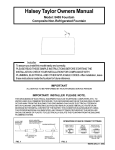
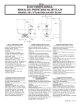
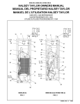
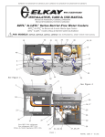
EDF14C
Installation/Care/Use Manual
SEE FIG. 2
15
Installer
To assure you install this model easily and correctly, PLEASE READ THESE SIMPLE
INSTRUCTIONS BEFORE STARTING THE INSTALLATION. CHECK YOUR INSTALLATION FOR COMPLIANCE WITH PLUMBING, ELECTRICAL AND OTHER APPLICABLE
CODES. After installation, leave these instructions inside the fountain for future reference.
IMPORTANT
ALL SERVICE TO BE PERFORMED BY AN AUTHORIZED SERVICE PERSON
IMPORTANT! INSTALLER PLEASE NOTE.
THE GROUNDING OF ELECTRICAL EQUIPMENT SUCH AS TELEPHONE, COMPUTERS, ETC. TO
WATER LINES IS A COMMON PROCEDURE. THIS GROUNDING MAY BE IN THE BUILDING OR MAY
OCCUR AWAY FROM THE BUILDING. THIS GROUNDING CAN CAUSE ELECTRICAL FEEDBACK INTO A
FOUNTAIN, CREATING AN ELECTROLYSIS WHICH CAUSES A METALLIC TASTE OR AN INCREASE IN
THE METAL CONTENT OF THE WATER. THIS CONDITION IS AVOIDABLE BY USING THE PROPER
MATERIALS AS INDICATED. ANY DRAIN FITTINGS PROVIDED BY THE INSTALLER SHOULD BE MADE
OF PLASTIC TO ELECTRICALLY ISOLATE THE FOUNTAIN FROM THE BUILDING PLUMBING SYSTEM.
INSTALLATION INSTRUCTIONS
1. Wall should already be framed for the fountain using the positioning dimensions shown in Figure 1. Shown dimensions pertain to
installation location (framing must support up to 150 lbs. weight).
2. Install rough-in plumbing as shown in Figure 1. Waste line should extend a minimum of 2" (51mm) through the back panel. Connect
ing lines to be copper and thoroughly flushed to remove all foreign matter before connection to fountain. Run the supply water inlet
line through the back panel. Install a service stop (not provided). Turn on supply water and flush thoroughly.
3. Secure the fountain to the wall using (6) bolts and washers (not provided). Tighten securely.
4. Remove elbow from end of p-trap and attach it to drain tube. Reattach elbow to p-trap and cut waste tube to required length
using plumbing hardware and trap as a guide.
5. Make water supply connections from service stop to the fountain. Turn on water supply and check for leaks. Newly installed
water supply line should be insulated after leak check is completed.
6. These products are designed to operate on 20-105 PSIG supply line pressure. If inlet pressure is above 105 PSIG, a pressure
regulator must be installed in the supply line. Any damage caused by reason of connecting these products to supply line pres
sures lower than 20 PSIG or higher than 105 PSIG is not covered by warranty.
7. Check stream height from bubbler. Stream height is factory set at 35 PSI. If supply pressure varies greatly from this, turn
adjustment screw on the regulator (Item 5). Clockwise adjustment will raise stream height and counter-clockwise will lower stream
height. For best adjustment stream should hit basin approximately 6-1/2" (165mm) from bubbler.
TROUBLE SHOOTING AND MAINTENANCE
1. Orifice Assy: Mineral deposits on orifice can cause water flow to spurt or not regulate. Mineral deposits may be removed from
orifice with a small round file not over 1/8" diameter or a small diameter wire. CAUTION: Do not file or cut orifice materials.
97256C Rev. A 4/05
EDF14C
FLOOR LINE
LEGEND
A = RECOMMENDED WATER SUPPLY LOCATION 3/8 O.D.TUBE CONNECT
STUBBED 1" (25mm)FROM WALL SHUT OFF BY OTHERS
B = RECOMMENDED LOCATION FOR WASTE OUTLET 1-1/4" O.D. DRAIN
STUBBED 6-5/8" (168mm) FROM WALL
C = 1-1/4" TRAP FURNISHED
D = 1/4" (6mm) DIA. HOLES FOR SECURING FOUNTAIN TO WALL
FIG. 1
ITEM NO.
1
2
3
4
5
6
7
8
9
10
11
12
13
14
15
NS
PARTS LIST
PART NO.
DESCRIPTION
LK142
40089C
40048C
10031C
61313C
A52919
40319C
50314C
45675C
A54800
100322740560
A54888
72460042
70012C
28577C
LK464
BUBBLER ASSY
COVER NUT
BUTTON
RETAINING NUT
REGULATOR
O-RING
ORIFICE FITTING
ORIFICE FLOW STRAIGHTNER
BUBBLER BODY
NIPPLE
GASKET
SCREEN
WASHER
LOCKNUT - 3/8 - 18
FOUNTAIN BODY
DRAIN
2
3
4
6, 7, 8
5
9
10, 11
12
13
14
FIG. 2
PRINTED IN U.S.A
FOR PARTS, CONTACT YOUR LOCAL DISTRIBUTOR OR CALL 1.800.323.0620
ELKAY MANUFACTURING COMPANY • 2222 CAMDEN COURT • OAK BROOK, IL 60523 • 630.574.8484
97256C Rev. A 4/05
PAGE 2
1