1
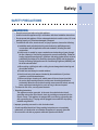
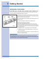
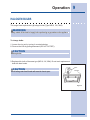
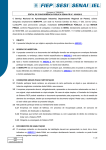
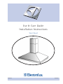
Use & Care Guide
Installation Instructions
Vent Hood
E40PV100FS
5995465571
2 Finding Information
READ AND SAVE THESE INSTRUCTIONS
Attach your sales
receipt to this
page for future
reference.
NOTE
Installer: Leave instructions with owner.
Owner: Read your Hood Use & Care Manual. It contains important safety information for
operating this appliance. It also has many suggestions for getting the best results from your
hood.
Read all instructions before installing the hood.
For your safety, please read and observe all safety instructions. This guide will
help you anticipate all installation connections.
QUESTIONS?
For toll-free telephone support in the U.S. and Canada:
1-877- 4ELECTROLUX (1-877-435-3287)
For online support and Internet product information:
www.electroluxusa.com
©2006 Electrolux Home Products, Inc.
Post Office Box 212378, Augusta, Georgia 30917, USA
All rights reserved. Printed in the USA
Finding Information
TABLE OF CONTENTS
Finding Information .............................................. 2
Please Read And Save This Guide ................... 2
Make A Record For Quick Reference ................ 2
Questions........................................................... 2
Table Of Contents .............................................. 3
Safety ..................................................................... 4
Important Safety Instructions ............................. 4
General Precautions .......................................... 5
Getting Started...................................................... 8
Operating Your Hood ......................................... 8
Care and Cleaning ...............................................11
Cleaning the Filters and Hood ..........................11
Installation........................................................... 12
Installation Planning......................................... 12
Verifying Package Contents............................. 13
Installing the Ductwork..................................... 14
Installing the Support System .......................... 15
Connecting the Decorative Flue ...................... 16
Installing the Duct Collar .................................. 16
Mounting the Hood to Support Frame ............. 17
Installing the Electrical ..................................... 17
Connecting the Ductwork................................. 18
Replacing the Bottom Trim .............................. 18
Installing the Filters .......................................... 19
Troubleshooting ................................................ 20
If Service is Required....................................... 20
Troubleshooting Guide..................................... 21
Energy Saving Tips .......................................... 22
Warranty Information ......................................... 24
3
4 Safety
IMPORTANT SAFETY INSTRUCTIONS
Safety Precautions
Do not attempt to install or operate your unit until you have read the safety
precautions in this manual. Safety items throughout this manual are labeled with a
Warning or Caution based on the risk type.
Definitions
This is the safety alert symbol. It is used to alert you to potential personal injury
hazards. Obey all safety messages that follow this symbol to avoid possible injury
or death.
WARNING
WARNING indicates a potentially hazardous situation which, if not avoided, could result in
death or serious injury.
CAUTION
CAUTION indicates a potentially hazardous situation which, if not avoided, may result in
minor or moderate injury.
CAUTION
CAUTION used without the safety alert symbol indicates a potentially hazardous situation
which, if not avoided, may result in property damage.
IMPORTANT
Indicates installation, operation or maintenance information which is important but not
hazard related.
Safety
SAFETY PRECAUTIONS
WARNING
• Read all instructions before using this appliance.
• Install or locate this appliance only in accordance with these installation instructions.
• Do not operate this appliance if it has a damaged electrical conduit or wires, if it is not
working properly or if it has been damaged or dropped.
• To reduce the risk of fire, electric shock, or injury to persons, observe the following:
a) Installation work and electrical wiring must be done by qualified person(s)
in accordance with all applicable codes and standards, including fire-rated
construction.
b) Sufficient air is needed for proper combustion and exhausting of gases through
the flue (chimney) of fuel burning equipment to prevent back drafting. Follow the
heating equipment manufacturer’s guidelines and safety standards such as those
published by the National Fire Protection Association (NFPA), and the American
Society for Heating, Refrigeration and Air Conditioning Engineers (ASHRAE), and
the local code authorities.
c) When cutting or drilling into wall or ceiling, do not damage electrical wiring and
other hidden utilities.
d) Ducted fans must always be vented outdoors.
e) Use this unit only in the manner intended by the manufacturer. If you have
questions, contact the manufacturer.
f) Before servicing or cleaning unit, switch power off at service panel and lock
the service disconnecting means to prevent power from being switched on
accidentally. When the service disconnecting means cannot be locked, securely
fasten a prominent warning device, such as a tag, to the service panel.
• To reduce the risk of fire, use only metal ductwork.
• Grounding Instructions
This appliance must be grounded. In the event of an electrical short circuit,
grounding reduces the risk of electric shock by providing an escape wire for the
electric current. This appliance is equipped with a cord having a grounding wire
with a grounding plug. The plug must be plugged into an outlet this is properly
installed and grounded.
• Improper grounding can result in a risk of electric shock.
• Consult a qualified electrician if the grounding instructions are not completely
understood, or if doubt exists as to whether the appliance is properly grounded.
• Do not use this unit with any separate solid-state speed control device.
5
6 Safety
WARNING
• Do not use an extension cord. If the power supply cord is too short, have a qualified
electrician install an outlet near the appliance.
• This appliance should be serviced only by qualified service personnel. Contact the
nearest Electrolux authorized servicer at (877) 435-3287, or at www.electroluxusa.com
for examination, repair or adjustment.
• If the information in this manual is not followed exactly, a fire or explosion may result
causing property damage, personal injury, or death.
• Do not store or use gasoline or other flammable vapors and liquids in the vicinity of this
or any other appliance.
• Improper installation, adjustment, alteration, service, or maintenance can cause
personal injury or property damage. Refer to these instructions and the accompanying Use & Care Manual. For assistance or additional information, consult a qualified
installer, service agency, or dealer.
• Keep appliance area clear and free from combustible material.
• For general ventilating use only. Do not use to exhaust hazardous or explosive
materials and vapors.
• To reduce the risk of a range top grease fire:
a) Never leave surface units unattended at high settings. Boilovers cause
smoking and greasy spillovers that may ignite. Heat oils slowly on low or
medium settings.
b) Always turn hood ON when cooking at high heat or when cooking flaming
foods.
c) Clean ventilating fans frequently. Grease should not be allowed to accumulate
on fan or filter.
d) Use proper pan size. Always use cookware appropriate for the size of the
surface element.
Safety
CAUTION
• To reduce risk of fire and to properly exhaust air, be sure to duct air outside. Do not
vent exhaust air into spaces within walls or ceilings or into attics, crawl spaces, or
garages.
• Take care when using cleaning agents or detergents.
• Avoid using food products that produce flames under the Range Hood.
• For general ventilating use only. Do not use to exhaust hazardous or explosive
materials and vapors
• To avoid motor bearing damage and noisy and/or unbalanced impellers, keep drywall
spray, construction dust, etc. off power unit.
• Your hood motor has a thermal overload which will automatically shut off the motor if it
becomes overheated. The motor will restart when it cools down. If the motor continues
to shut off and restart, have the hood serviced.
• For best capture of cooking impurities, the bottom of the hood should be a minimum
of 24” and a maximum of 30” above the cooking surface. See “Installing the Support
System” section for mounting restrictions.
• Two installers are recommended because of the large size and weight of this hood.
• This product is equipped with a thermostat which may start blower automatically. To
reduce the risk of injury and to prevent power from being switched on accidentally,
switch power off at service panel and lock or tag service panel.
• Please read specification label on product for further information and requirements.
• Use with approved cord-connection kit only.
7
8 Getting Started
OPERATING YOUR HOOD
The hood is operated using the slide controls under the front edge of the hood.
The light switch turns the halogen lights on and off.
LIGHT
SWITCH
BLOWER
SPEED
CONTROL
The blower on/off switch turns the blower on to the running
speed set by the blower speed control. The blower must be
turned on and off using this switch.
BLOWER
ON/OFF
SWITCH
The blower speed control changes the running speed of the
blower (1-2-3).
The pilot lamp lights up whenever the blower is on.
PILOT
LAMP
Figure 1
Auto-Start Heat Sensing System
Your hood is equipped with an Auto-Start Heat Sensing
System thermostat. This thermostat is a device that will turn
on or speed up the blower if it senses excessive heat above
the cooking surface.
1 If blower is OFF - it turns blower ON to HIGH speed.
2 If blower is ON at a lower speed setting - it turns blower
up to HIGH speed.
When the temperature level drops to normal, the blower will
return to its original setting.
WARNING
The Auto-Start Heat Sensing System thermostat can start the blower even if the hood is
turned OFF. When this occurs, it is impossible to turn the blower OFF with its switch. If you
must stop the blower, do it from the main electrical panel.
Operation
9
HALOGEN BULBS
This range hood requires four (4) halogen bulbs (Type MR16, 12V, 20W).
WARNING
Always switch off the electrical supply before performing any operations on the appliance.
To change bulbs:
1 Loosen the ring nut by turning it counterclockwise.
2 Remove the bulb by pulling downward (DO NOT ROTATE).
CAUTION
Bulb may be hot.
3 Replace with a bulb of the same type (MR16, 12V, 20W). Do not touch replacement
bulb with bare hands.
CAUTION
Use of bulbs greater than 20 watts will cause the fuse to open..
BULB
RING NUT
Figure 2
10 Operation
FUSE REPLACEMENT
IF LIGHTS FAIL TO OPERATE, DISCONNECT POWER AT THE
SERVICE ENTRANCE. CHECK THE FUSE AND REPLACE IF
NECESSARY.
1 Remove grease filters.
2 Remove the electrical box support and open the fuse box.
3 Unscrew the cap from the fuse holder and remove the fuse.
4 Replace the fuse with the same size and amperage (5 x 20mm,
4 amp, 125 volt).
FUSE/S
CAUTION
Figure 3
Use of a fuse greater than 4 amps may damage the transformer.
5 Reconnect power at the service entrance.
Care and Cleaning
CLEANING THE FILTERS AND HOOD
Proper maintenance of the Range Hood will assure proper performance of the unit.
Grease Filters
The grease filters should be cleaned frequently. Use a warm detergent solution.
Grease filters are dishwasher safe.
See “INSTALL FILTERS” section for removal and installation instructions.
Hood Cleaning
Stainless steel is one of the easiest materials to keep clean. Occasional care will
help preserve its fine appearance.
Cleaning tips:
1 Hot water with soap or detergent is all that is usually needed.
2 Follow all cleaning by rinsing with clear water. Wipe dry with a clean, soft cloth
to avoid water marks.
3 For discolorations or deposits that persist, use a non-scratching household
cleanser or stainless steel polishing powder with a little water and a soft cloth.
4 For stubborn cases, use a plastic scouring pad or soft bristle brush together
with cleanser and water. Rub lightly in direction of polishing lines or “grain” of the
stainless finish. Avoid using too much pressure which may mar the surface.
5 DO NOT allow deposits to remain for long periods of time.
6 DO NOT use ordinary steel wool or steel brushes. Small bits of steel may
adhere to the surface causing rust.
7 DO NOT allow salt solutions, disinfectants, bleaches, or cleaning compounds
to remain in contact with stainless steel for extended periods. Many of these
compounds contain chemicals which may be harmful. Rinse with water after
exposure and wipe dry with a clean cloth.
Painted surfaces should be cleaned with warm water and mild detergent only.
11
12 Installation
INSTALLATION PLANNING
A qualified installer must complete the installation of this built-in appliance. Proper
installation is your responsibility.
Carefully check the location where the hood is to be installed. The hood should be
placed for convenient access. Make certain that electrical power can be provided
in the selected location.
Plan the installation so that all minimum clearances are met or exceeded.
Dimensions shown provide minimum clearances, unless otherwise noted.
Make certain that you have everything necessary to ensure a proper
installation before proceeding.
Installation
13
VERIFY PACKAGE CONTENTS
Unpack hood and check contents.
You should receive:
1 - Hood
1 - Decorative Flue Assembly
1 - Support Frame
1 - Duct Collar
1 - Parts Bag containing:
8 - Washers ø 6.4
4 - Washers ø 4.5
4 - Lag Bolts
8 - Mounting Screws (3.9 X 9.5mm Pan Head)
4 - Hex Nuts
1 - Installation Instructions
2 - Warranty Cards
4 HEX NUTS
DUCT COLLAR
DECORATIVE
FLUE
SUPPORT
FRAME
8 WASHERS
ø6.4
4 Lag Bolts
(6x70mm)
Figure 4
4 WASHERS
ø4.5
8 MOUNTING SCREWS
(3.9 x 9.5mm Pan Head)
14 Installation
INSTALLING THE DUCTWORK
CAUTION
To reduce the risk of fire, use only metal ductwork.
1 Decide where the ductwork will run between the hood and the outside. Figure 5.
2 A straight, short duct run will allow the hood to perform most efficiently.
3 Long duct runs, elbows, and transitions will reduce the performance of the hood. Use
as few of them as possible. Larger ducting may be required for best performance
with longer duct runs.
4 Install a roof or wall cap. Connect round metal ductwork to cap and work back
towards hood location. Use duct tape to seal the joints between ductwork
sections.
ROOF CAP
8”
ROUND
DUCT
DECORATIVE
FLUE
HOOD
8”
ROUND
ELBOW
EAVE
VENT
24” to 30” ABOVE COOKING
SURFACE (See “Install Mounting
Bracket” section for mounting
restrictions).
Figure 5
15
Installation
INSTALLING THE SUPPORT SYSTEM
1 At hood location, install 2 x 4 cross framing between ceiling joists
using dimensions shown in Figure 6.
2 Finish the ceiling surface. Be sure to mark the location of the
ceiling joists and cross framing.
3 Measure the ceiling height and determine distance between the cook
top and bottom of hood.
4 Per the chart, adjust overall length of the support frame as shown in
Figure 7. Remove and reinstall (4) screws in the height adjustment
slots to achieve proper length. Install (4) additional 3.9 x 9.5mm
screws and 4.5 diameter washers from the Hardware Parts Bag.
TOP VIEW OF SUPPORT FRAME
9-13/16”
7-13/16”
Figure 6
SUPPORT FRAME HEIGHT ADJUSTMENT CHART
CEILING
HEIGHT
HOOD DISTANCE ABOVE 36” HIGH COOKTOP (SEE NOTE A)
24”
25”
26”
27”
28”
29”
30”
SUPPORT FRAME LENGTH
8-FEET
25”
24”
23”
9-FEET
10-FEET
(See note B)
SCREWS
3.9 X
9.5mm (8)
31”
46”
45”
44”
43”
WASHERS
4.5 DIA (8)
NOTE
Figure 7
A. Minimum hood distance above the cook top must not be less than 24”.
A maximum of 30” above the cook top is highly recommended for best
capture of cooking impurities.
Distances over 30” above the cook top are at the installer’s and user’s
discretion - providing that the ceiling height and flue length permit.
DRYWALL
CROSS
FRAMING
9-13/16”
B. Requires optional 10-foot flue extension model EXPV100S.
CEILING
JOISTS
5 Secure the support frame to ceiling joists and cross framing with
(4) 6 x 70mm lag bolts and 6.4 diameter washers provided. Make
sure the bolts are driven into centers of joists and cross framing for
maximum strength. See Figure 8.
6 Run 2-wire plus ground electrical cable through the hole on top of
the support frame bracket. Cable length must extend at least 12”
below the bottom of the support frame. Secure cable to the support
frame with an appropriate cable connector.
WASHER
MOUNTING
SCREWS
(6 x 70mm)
FRONT
SUPPORT
FRAME
HEIGHT
ADJUSTMENT
SLOTS
Figure 8
16 Installation
CONNECTING THE DECORATIVE FLUE
1 Secure the upper flue to the upper support frame with the mounting screws (3.9
x 9.5mm).
2 Insert the lower flue moving it completely towards the top and secure it temporarily
with retaining screws (3.9 x 9.5mm).
MOUNTING
SCREWS
(3.9 x 9.5mm)
INSERT THE LOWER FLUE
UPPER
FLUE
RETAINING
SCREW
(3.9 x 9.5mm)
LOWER
FLUE
Figure 10
Figure 9
INSTALLING THE DUCT COLLAR
1 Fold the 2 tongues outwards.
2 Secure the discharge collar to the hood with (2) retaining screws
(3.90 x 9.5mm).
RETAINING
SCREWS
(3.9 x 9.5mm)
DISCHARGE COL-
TON-
Figure 11
Installation
17
MOUNTING THE HOOD TO SUPPORT FRAME
1 Insert four (4) bolts through the top of the hood from the inside.
2 Use four (4) nuts and four (4) washers to secure hood to support frame.
WASHER
NUT
BOLT
Figure 12
INSTALLING THE ELECTRICAL
WARNING
Electrical wiring must be done by a qualified person(s) in accordance with all applicable
codes and standards. This range hood must be properly grounded. Turn off electrical power
at service entrance before wiring.
1 Remove the wiring box cover. Remove a knockout from the wiring
box.
2 Feed 6” of power cable through the knockout opening and secure
cable to the wiring box with an appropriate connector.
3 Make electrical connections. Connect white to white, black to black
and green to green.
4 Replace wiring box cover and screws. Check that wires are not
pinched between cover and box.
WIRING BOX COVER
Figure 13
18 Installation
CONNECTING THE DUCTWORK
LOWER
FLUE
RETAINING
SCREWS
8” ROUND
METAL
DUCT
1 Use 8” round metal duct to connect the discharge collar on the hood to
the ductwork above.
2 Use duct tape to make all joints secure and air tight.
3 Remove the two temporary retaining screws from the lower flue and set
it in place on the hood.
4 Secure decorative flue to hood with two mounting screws (3.9 x 9.5mm).
pan head mounting screws.
Figure 14
MOUNTING
SCREWWS
(3.9 x 9.5 mm)
Figure 15
REPLACING THE BOTTOM TRIM
1 Remove the four (4) screws from the inside of the hood.
2 Remove the trim by pulling downward.
3 Slide the new trim upward into hood.
4 Replace the four screws inside hood.
Figure 16
19
INSTALLING THE FILTER(S)
1 To remove the grease filter, grip the latch and pull it down. This will disengage the
filters from the hood. Tilt the filter downward and remove.
2 To install the grease filter, align rear filter tabs with slots in the hood. Pull latch
tab down, push filter up into position and release the tab. Make sure the filter is
securely engaged after installation.
NOTE
Prior to use, remove protective film from the filter frame.
GREASE
FILTERS
Figure 17
20 Troubleshooting
IF SERVICE IS REQUIRED
First, review the recommended checks listed in the Troubleshooting Guide.
Then, be certain that the appliance has been installed properly and is being
operated correctly. Familiarize yourself with the warranty terms and conditions
listed in the Warranty section.
If the above checks have been completed and the problem has not yet been
remedied, contact the dealer where you purchased the unit. State the Model and
Serial number and explain the problem. The Model and Serial number plate is
located inside the unit at upper right hand corner.
If you do not know the name of the selling dealer or local service company, you
can check online at www.electroluxusa.com.
Troubleshooting
TROUBLESHOOTING GUIDE
IMPORTANT
Unnecessary service calls may be expensive, frustrating and time consuming. Before you
call for service, please review the potential problems, possible causes and remedies shown
in the table below.
Troubleshooting - What to check when problems occur
Problem
Possible Cause
Remedy
Nothing works.
Vent power supply
interrupted or not energized.
Have electrician check power supply,
including house circuit breaker and
fuses.
Lights do not turn on.
A loose or burned out light.
Check the light.
Blown fuse.
Check lamp fuse and replace if open.
21
22 Saving Energy
ENERGY SAVING TIPS
1
Do not operate the blower at a speed that is higher than necessary to
remove the cooking exhaust. Running at excessive speeds removes more air
from the inside of the house that must be replaced by outside air. This may
be especially costly when the housing air conditioning or heating system is in
operation.
2
Clean filters and grease-laden surfaces often to improve efficiency.
3
Turn off the blower as soon as all cooking smoke and odors have been
eliminated.
4
Always use lids on cookware to retain heat and moisture.
5
Minimize the amount of liquid used to cook food.
6
Select cookware of the proper size, material and construction for the cooking
task being performed.
23
24 Warranty
14 Warranty Information
HOOD WARRANTY Your hood is protected by this warranty
WARRANTY
PERIOD
THROUGH OUR AUTHORIZED SERVICERS,
WE WILL:
THE CONSUMER WILL BE
RESPONSIBLE FOR:
FULL ONE-YEAR
WARRANTY
One year from
original purchase
date.
Pay all costs for repairing or replacing any parts of this
product which prove to be defective in materials or
workmanship.
Costs of service calls that are listed under
NORMAL RESPONSIBILITIES OF THE
CONSUMER.*
LIMITED
WARRANTY
(Applicable to the
State of Alaska)
Time periods listed
above.
All of the provisions of the full warranties above and the
exclusions listed below apply.
Costs of the technician’s travel to the home and
any costs for pick up and delivery of the appliance
required because of service.
In the U.S.A., your appliance is warranted by Electrolux Home Products, Inc. We authorize no person to change or add to any of our obligations
under this warranty. Our obligations for service and parts under this warranty must be performed by us or an authorized Electrolux Home Products,
Inc. servicer. In Canada, your appliance is warranted by Electrolux Canada Corp.
*NORMAL
RESPONSIBILITIES
OF THE CUSTOMER
This warranty applies only to products in ordinary household use, and the consumer is responsible for the items
listed below:
1. Proper use of the appliance in accordance with instructions provided with the product.
2. Proper installation by an authorized servicer in accordance with instructions provided with the appliance and in
accordance with all local plumbing, electrical and/or gas codes.
3. Proper connection to a grounded power supply of sufficient voltage, replacement of blown fuses, repair of loose
connections or defects in house wiring.
4. Expenses for making the appliance accessible for servicing, such as removal of trim, cupboards, shelves, etc., which
are not a part of the appliance when it was shipped from the factory.
5. Damages to finish after installation.
6. Replacement of light bulbs and/or fluorescent tubes (on models with these features).
EXCLUSIONS
This warranty does not cover the following:
1. CONSEQUENTIAL OR INCIDENTAL DAMAGES SUCH AS PROPERTY DAMAGE AND INCIDENTAL EXPENSES
RESULTING FROM ANY BREACH OF THIS WRITTEN OR ANY IMPLIED WARRANTY.
Note: Some states do not allow the exclusion or limitation of incidental or consequential damages, so this limitation or
exclusion may not apply to you.
2. Service calls which do not involve malfunction or defects in workmanship or material, or for appliances not in ordinary
household use. The consumer shall pay for such service calls.
3. Damages caused by services performed by servicers other than Electrolux Home Products, Inc., Electrolux Canada
Corp., or its authorized servicers; use of parts other than genuine Electrolux Home Products parts; obtained from
persons other than such servicers; or external causes such as abuse, misuse, inadequate power supply or acts of God.
4. Products with original serial numbers that have been removed or altered and cannot be readily determined.
IF YOU NEED
SERVICE
Keep your bill of sale, delivery slip, or some other appropriate payment record. The date on the bill establishes the
warranty period should service be required. If service is performed, it is in your best interest to obtain and keep all
receipts. This written warranty gives you specific legal rights. You may also have other rights that vary from state to state.
Service under this warranty must be obtained by contacting Electrolux Home Products, Inc. or Electrolux Canada Corp.
This warranty only applies in the 50 States of the U.S.A. and Puerto Rico, and Canada. Product features or specifications as described or illustrated
are subject to change without notice. All warranties are made by Electrolux Home Products, Inc. In Canada, your appliance is warranted by
Electrolux Canada Corp.
USA
1-877-4ELECTROLUX
Electrolux Home Products, Inc.
P.O. Box 212378
Augusta, GA 30917
Canada
1-866-294-9911
Electrolux Canada Corp.
6150 McLaughlin Road
Mississauga, Ontario
L5R 4C2