1
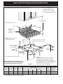
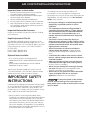
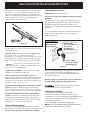
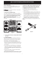
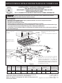
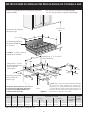
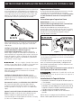
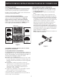
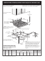
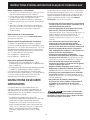
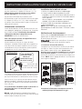
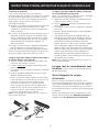
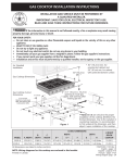
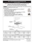
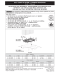
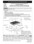
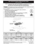
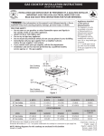
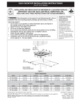
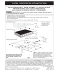
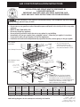
GAS COOKTOP INSTALLATION INSTRUCTIONS
INSTALLATION AND SERVICE MUST BE PERFORMED BY
A QUALIFIED INSTALLER.
IMPORTANT: SAVE FOR LOCAL ELECTRICAL INSPECTOR'S USE.
READ AND SAVE THESE INSTRUCTIONS FOR FUTURE REFERENCE.
If the information in this manual is not followed exactly, a fire or explosion may result causing
property damage, personal injury or death.
FOR YOUR SAFETY:
— Do not store or use gasoline or other flammable vapors and liquids in the vicinity of this or any other
appliance.
— WHAT TO DO IF YOU SMELL GAS:
• Do not try to light any appliance.
• Do not touch any electrical switch; do not use any phone in your building.
• Immediately call your gas supplier from a neighbor's phone. Follow the gas supplier's instructions.
• If you cannot reach your gas supplier, call the fire department.
— Installation and service must be performed by a qualified installer, service agency or the gas supplier.
For Standard
Installation:
Gas Cooktop Dimensions
30"(76.2 cm)
Min.*
B
A
* 30" (76.2 cm) min. for
unprotected cabinet and
24" (61 cm) min. for cabinet
with protected bottom surface.
C
Gas Cooktop Cutout
Dimensions
4" X 4" (10.2 cm x 10.2
cm) opening to route gas
supply.
3"(7.6 cm)
2 1/2"
(6.4 cm)
2"(5.1 cm) Dia.
Opening to route
power cable
71/4"
(18.4 cm)
J
E
2"(5.1 cm)
G
1" (2.5 cm)
D
F
H
Figure 1
MODEL
A. LENGTH
B. WIDTH
C. DEPTH
D**
36 (91.4)
30 (76.2)
7
35 /8 (91.1)
297/8 (75.9)
25 (63.5)
25 (63.5)
15
7¾ (19.7) 35 /16 (91.3)
7¾ (19.7) 2915/16 (76)
LENGTH
E**
**Note: D & E are critical to the proper
installation of the cooktop. D reflects the
finished dimension. Due to the variation in
countertop materials, it is recommended to first
undercut this dimension, and then adjust it
upon installation of the cooktop.
CUTOUT DIMENSIONS
WIDTH
F
G
J. DEPTH BELOW
COOKTOP
H
353/16 (89.4) 351/8 (89.2) 22 (55.9) 11/8 (2.9) Max.
293/16 (74.1) 291/8 (74) 22 (55.9) 11/8 (2.9) Max.
All dimensions are stated in inches and (cm).
NOTE: Wiring diagrams for this cooktop are enclosed in this booklet
1
71/2 (19.1)
71/2 (19.1)
318201475 (0710) Rev. D
English - pages 1-8
Español - páginas 9-16
Français - pages 17-23
Wiring Diagram page - 24
GAS COOKTOP INSTALLATION INSTRUCTIONS
* 30" (76.2 cm) min. for
unprotected cabinet and
24" (61 cm) min. for cabinet
with protected bottom surface.
For Installation with the optional Stainless Steel Backsplash.
30"(76.2 cm)
Min.*
Gas Cooktop Dimensions
A
2"(5.1 cm)
B
9" (22.9 cm)
Optional
Stainless Steel
Backsplash
C
***Note: Applies only in case
of countertop backwall.
4"X 4" (10.2 cm x 10.2 cm)
opening to route gas supply.
K***
3"(7.6 cm)
2 1/2"
(6.4 cm)
2" (5.1 cm) Dia.
opening to route
power cable.
J
2"(5.1 cm)
E
G
1" (2.5 cm)
H
7¼" (18.4 cm)
D
F
Gas Cooktop Cutout Dimensions
Do not slide unit into cabinet cutout.
Protruding screws on the bottom of unit
may damage the bottom front finish.
MODEL
A. LENGTH
B. WIDTH
C. DEPTH
36 (91.4)
30 (76.2)
357/8 (91.1)
297/8 (75.9)
25 (63.5)
25 (63.5)
7¾ (19.7)
7¾ (19.7)
Figure 2
**Note: D & E are critical to the proper
installation of the cooktop. D reflects the
finished dimension. Due to the variation in
countertop materials, it is recommended to first
undercut this dimension, and then adjust it
upon installation of the cooktop.
CUTOUT DIMENSIONS
LENGTH
WIDTH
D**
E**
F
G
H
J. DEPTH K. COUNTERTOP
BELOW
BACKWALL
COOKTOP
CUTOUT
3515/16 (91.3) 353/16 (89.4) 351/8 (89.2) 22 (55.9) 11/8 (2.9) Max. 7½ (19.1)
2915/16 (76) 293/16 (74.1) 291/8 (74) 22 (55.9) 11/8 (2.9) Max. 7½ (19.1)
All dimensions are stated in inches and (cm).
2
3515/16 (91.3)
2915/16 (76)
GAS COOKTOP INSTALLATION INSTRUCTIONS
Important Notes to the Installer
This cooktop has been design certified by CSA
International. As with any appliance using gas and
generating heat, there are certain safety precautions you
should follow. You will find them in the Use and Care
Guide, read it carefully.
1. Read all instructions contained in these installation
instructions before installing the cooktop.
2. Remove all packing material before connecting the
electrical supply to the cooktop.
3. Observe all governing codes and ordinances.
4. Be sure to leave these instructions with the consumer.
5. Note: For operation at 2000 ft. elevations above see
level, appliance rating shall be reduced by 4 percent
for each additional 1000 ft.
• Be sure your cooktop is installed and grounded
properly by a qualified installer or service
technician.
• This cooktop must be electrically grounded in
accordance with local codes or, in their absence,
with the National Electrical Code ANSI/NFPA No.
70—latest edition in the United States, or in
Canada, with the Canadian Electrical Code, CSA
C22.1 Part 1.
• The burners can be lit manually during an
electrical power outage. To light a burner, hold a
lit match to the burner head, then slowly turn the
Surface Control knob to LITE. Use caution when
lighting burners manually.
• Do not store items of interest to children in
cabinets above the cooktop. Children could be
seriously burned climbing on the cooktop to reach
items.
• To eliminate the need to reach over the surface
burners, cabinet storage space above the burners
should be avoided.
• Adjust surface burner flame size so it does not
extend beyond the edge of the cooking utensil.
Excessive flame is hazardous.
• Never use your cooktop for warming or heating
the room. Prolonged use of the cooktop without
adequate ventilation can be hazardous.
• Do not store or use gasoline or other flammable
vapors and liquids near this or any other
appliance. Explosions or fires could result.
Important Note to the Consumer
Keep these instructions with your Use and Care Guide for
future reference.
Depth Adjustment Filler Kit
This cooktop is designed to replace existing unit. If the
depth of your countertop opening is bigger than 7¼" (18.4
cm) and less than 8½" (21.6 cm) you can order a free filler
kit by calling Service Center at 1-877-4ELECTROLUX (1877-435-3287).
For 36" model : #903051-9010
For 30" model : #903051-9100
Optional Items Available:
• A 9" (22.9 cm) Stainless Steel Backsplash Kit
#903048-9010 for 36" model or #903048-9100 for 30"
model.
• A Black Knobs Kit #903049-9120 for 36" model or
#903049-9110 for 30" model.
Those kits can be order through the Service Center at
1-877-4ELECTROLUX (1-877-435-3287). However all cost
related to those kits will be at customer charges.
IMPORTANT SAFETY
INSTRUCTIONS
The electrical power to the cooktop
must be shut off while gas line connections are
being made. Failure to do so could result in serious
injury or death.
Installation of this cooktop must conform with local codes
or, in the absence of local codes, with the National Fuel
Gas Code ANSI Z223.1/NFPA54—latest edition in the
United States, or in Canada, with the Canadian Fuel Gas
Code, CAN/CGA B149 and CAN/CGA B149.2.
• When installed in a manufactured (mobile) home
installation must conform with the Manufactured Home
Construction and Safety Standard, title 24 CFR, part
3280 [Formerly the Federal Standard for Mobile Home
Construction and Safety, title 24, HUD (part 280)] or,
when such standard is not applicable, the Standard for
Manufactured Home Installation, ANSI/NCSBCS A225.1
or with local codes where applicable.
3
GAS COOKTOP INSTALLATION INSTRUCTIONS
13" (33 cm) max. depth
for cabinet installed above
cooktop
A
30" (76.2 cm) Min.
Clearance Between the
Top of the Cooking
Platform and the Bottom
of an Unprotected Wood
or Metal Cabinet
24" (61 cm) Min.
when Bottom of Wood
or Metal Cabinet is
Protected by Not Less
Than 1/8" Flame
Retardant Millboard
Covered With Not Less
Than No. 28 MGS
Sheet Steel, 0.015"
(0.4 mm) Stainless
Steel, 0.024" (0.6 mm)
Aluminum or 0.020"
(0.5 mm) Copper
2" (5.1 cm) min. distance
between rear edge of
cutout and nearest
combustible surface
above countertop
18" (45.7 cm)
Min.
30" (76.2 cm) min.
clearance between
the top of the
cooking platform and
the bottom of an
unprotected wood or
metal cabinet.
C
B
24" (61 cm)
It is not recommended to use
drawer underneath cooktop.
To eliminate the risk of
burns or fire from reaching over heated
surfaces, cabinet storage space located
above the cooktop should be avoided. If
cabinet storage is provided, risk can be
reduced by installing a range hood that
projects horizontally a minimum of 7"
(17.8 cm) beyond the bottom of the
cabinets.
MODEL
A
36" (91.4 cm)
30" (76.2 cm)
36" (91.4 cm)
30" (76.2 cm)
Figure 3 – CABINET DESIGN
4
B. Minimum
Clearance from
Left Side
9" (22.9 cm)
5" (12.7 cm)
C. Minimum
Clearance from
Right Side
9" (22.9 cm)
5" (12.7 cm)
GAS COOKTOP INSTALLATION INSTRUCTIONS
The conversion must be performed by a qualified service
technician in accordance with the kit instructions and all
local codes and requirements. Failure to follow
instructions could result in serious injury or property
damage. The qualified agency performing this work
assumes responsibility for the conversion.
Wall Outlet Location
4"
(10.2 cm)
Failure to make the appropriate
conversion can result in serious personal injury and
property damage.
5"
(12.7 cm)
Important: Remove all packing material and
Recommended
area for 120V
grounded
outlet on rear
wall.
literature from cooktop before connecting gas and
electrical supply to cooktop.
Install Pressure Regulator
CENTRE
LINE
OF UNIT
16"
(40.6 cm)
Install the pressure regulator with the arrow on the
regulator pointing up toward the unit in a position where
you can reach the access cap.
NOTE: If an
outlet is not
available, have
one installed by
a qualified
technician.
Do not make the connection too tight.
The regulator is die cast. Overtightening may crack the
regulator resulting in a gas leak and possible fire or
explosion.
Figure 4
CENTRE
LINE
OF UNIT
Manual
Shutoff
Valve
GAS FLOW
Flare
Union
Flare
Union
Pressure
Regulator
Provide an Adequate Gas Supply
This cooktop is designed to operate on natural gas at 4"
(10.2 cm) of manifold pressure only.
On
Nipple
Off
A pressure regulator is connected in series with the
manifold on the cooktop and must remain in series with
the supply line.
Nipple
Access
Cap
All connections must be wrench-tightened
Figure 5
For proper operation, the maximum inlet pressure to
the regulator must be no more than 14" (35.6 cm) of
water column (W.C.) pressure.
Assemble the flexible connector from the gas supply pipe
to the pressure regulator in the following order:
1. manual shutoff valve
2. 1/2" (1.3 cm) nipple
3. 1/2" (1.3 cm) flare union adapter
4. flexible connector
5. 1/2" (1.3 cm) flare union adapter
6. 1/2" (1.3 cm) nipple
7. pressure regulator
For checking the regulator, the inlet pressure must be at
least 1"(2.5 cm) (or 2.5 kPa) greater than the regulator
manifold pressure setting. The regulator is set for 4"
(10.2 cm) of manifold pressure, the inlet pressure must
be at least 5" (12.7 cm).
The gas supply line to the range should be 1/2" (1.3 cm)
or 3/4" (1.9 cm) pipe.
Use pipe-joint compound made for use with Natural and
LP/Propane gas to seal all gas connections. If flexible
connectors are used, be certain connectors are not
kinked.
LP/Propane Gas Conversion
This appliance can be used with Natural gas or LP/
Propane gas. It is shipped from the factory for use with
natural gas.
A kit for converting to LP gas is supplied with your
cooktop. The kit is marked "FOR LP/PROPANE GAS
CONVERSION".
Flexible
Connector
5
GAS COOKTOP INSTALLATION INSTRUCTIONS
The supply line should be equipped with an approved
shutoff valve. This valve should be located in the same
room as the cooktop and should be in a location that
allows ease of opening and closing. Do not block access
to the shutoff valve. The valve is for turning on or
shutting off gas to the appliance.
Grounding Instructions
IMPORTANT Please read carefully.
For personal safety, this appliance must be properly
grounded.
The power cord of this appliance is equipped with a 3prong (grounding) plug which mates with a standard 3prong grounding wall receptacle (see Figure 7) to
minimize the possibility of electric shock hazard from the
appliance.
The wall receptacle and circuit should be checked by a
qualified electrician to make sure the receptacle is
properly grounded.
Preferred Method
Figure 6
Do not, under
any circumstances,
cut, remove,
or bypass the
grounding prong.
Grounding type
wall receptacle
Once the regulator is in place, open the shutoff valve in
the gas supply line. Wait a few minutes for gas to move
through the gas line.
Check for leaks. After connecting the cooktop to the
gas supply, check the system for leaks with a
manometer. If a manometer is not available, turn on the
gas supply and use a liquid leak detector (or soap and
water) at all joints and connections to check for leaks.
Power supply
cord with 3-prong
grounding plug.
Do not use a flame to check for leaks
from gas connections. Checking for leaks with a flame
may result in a fire or explosion.
Figure 7
Where a standard 2-prong wall receptacle is installed, it
is the personal responsibility and obligation of the
consumer to have it replaced by a properly grounded 3prong wall receptacle.
Tighten all connections if necessary to prevent gas
leakage in the cooktop or supply line.
Check alignment of control knob valves after
connecting the cooktop to the gas supply to be sure the
cooktop manifold pipe has not moved. A misalignment
could cause the valve stems to rub on the control panel,
resulting in a gas leak at the valve.
Do not, under any circumstances, cut or remove the
third (ground) prong from the power cord.
Disconnect electrical supply cord from
wall receptacle before servicing cooktop.
Disconnect this cooktop and its individual shutoff
valve from the gas supply piping system during any
pressure testing of that system at test pressures greater
than 1/2 psig (3.5 kPa or 14" (35.6 cm) water column).
Cooktop Installation
Isolate the cooktop from the gas supply piping
system by closing its individual manual shutoff valve
during any pressure testing of the gas supply piping
system at test pressures equal to or less than 1/2 psig
(3.5 kPa or 14" (35.6 cm) water column).
1. Visually inspect the cooktop for damage.
2. If you are installing the optional Stainless Steel
backsplash, first fix it at the back of the cooktop using
the screws supplied with the kit and follow the
instructions attached.
3. Set the cooktop into the countertop cutout.
Electrical Requirements
NOTE: Do not use caulking compound; cooktop should
be removable for service when needed.
120 volt, 60 Hertz, properly grounded branch circuit
protected by a 15 amp circuit breaker or time delay fuse.
Do not use an extension cord with this cooktop.
6
GAS COOKTOP INSTALLATION INSTRUCTIONS
Check Operation
4. Adjust the "LOW" Setting of Regular Burner (see
figure 8) on the Surface Burner Valves (Figure 9):
a. Push in and turn control to LITE until burner ignites.
b. Quickly turn knob to LOWEST POSITION.
c. If burner goes out, reset control to OFF.
d. Remove the surface burner control knob and
decorative ring.
e. Insert a thin-bladed screwdriver into the hollow valve
stem and engage the slotted screw inside. Flame size
can be increased or decreased by turning the screw.
Turn counterclockwise to increase flame size. Turn
clockwise to decrease flame size. Adjust flame until
you can quickly turn knob from LITE to LOWEST
POSITION without extinguishing the flame. Flame
should be as small as possible without going out.
Note: Air mixture adjustment is not required on surface
burners.
Refer to the Use and Care Guide packaged with the
cooktop for operating instructions and for care and
cleaning of your cooktop.
Do not touch the burners. They may be
hot enough to cause burns.
1. Burner Bases and Burner Caps
This range is equipped with sealed burners as shown
(Figure 8). All pieces are at their place. Take note where
they are. Remove all packaging material located
under the Dual Surface burner head. Make sure the
burner is properly aligned and leveled.
NOTE: There are no burner adjustments necessary on
this range.
30” Model
Burner Cap
Burner Cap
Burner Base
36” model
Fixed Burner Ring
and Burner Base
Fixed Burner Ring
Dual Surface
Burner
Regular Burner
Figure 9
Figure 8
2. Turn on Electrical Power and Open Main Shutoff
Gas Valve
3. Check the Igniters
Operation of electric igniters should be checked after
range and supply line connectors have been carefully
checked for leaks and range has been connected to
electric power. To check for proper lighting:
a.Push in and turn a surface burner knob to the LITE
position. All electronic surface ignitors will spark at the
same time. However, only the burner you are turning
on will ignite.
b.The surface burner should light once the flow of gas
reached the surface burner. Each burner should light
within four (4) seconds in normal operation after air
has been purged from supply lines. Visually check that
burner has lit.
c. Once the burner lights, the control knob should be
rotated out of the LITE position.
There are separate ignition devices for each burner. Try each
knob separately until all burner valves have been checked.
7
GAS COOKTOP INSTALLATION INSTRUCTIONS
5. Adjust the "LOW" Setting of the Dual Burner (see
Figure 8) on the Surface Burner Valve (Figure 10):
Note: On the dual valve the low setting of each portion
(rear portion of bridge burner and the center portion of
bridge burner) should be adjusted individually.
a. Push in and turn control to LITE until the rear portion
of the bridge burner ignites only.
b. Quickly turn knob to LOWEST POSITION.
c. If burner goes out, reset control to OFF.
d. Remove the surface burner control knob.
e. The inner portion of the dual burner flame size can be
increased or decreased by turning screw A (see Figure
19). Use screw B to adjust the flame size of the outer
portion of the dual burner. Turn counterclockwise the
screw to increase flame size. Turn clockwise the
screw to decrease flame size. Adjust flame until you
can quickly turn knob from LITE to LOWEST POSITION
without extinguishing the flame. Flame should be as
small as possible without going out.
Note: Air mixture adjustment is not required on surface
burners.
When All Hookups are Complete
Make sure all controls are left in the OFF position.
Before You Call for Service
Read the Before You Call for Service Checklist and
operating instructions in your Use and Care Guide. It
may save you time and expense. The list includes
common occurrences that are not the result of defective
workmanship or materials in this appliance.
Refer to your Use and Care Guide for Electrolux Service
phone numbers, or call 1-877-4ELECTROLUX (1-877435-3287).
B
A
Figure 10
8
INSTRUCCIONES DE INSTALACION PARA PLANCHA DE COCINAR A GAS
LA INSTALACIÓN Y EL SERVICIO DEBEN SER REALIZADOS
POR UN INSTALADOR CALIFICADO.
IMPORTANTE: GUARDE ESTAS INSTRUCCIONES PARA USO DEL
INSPECTOR ELÉCTRICO LOCAL.
LEA Y GUARDE ESTAS INSTRUCCIONES PARA FUTURAS REFERENCIAS
Si todas las instrucciones de éste manual no son observadas a la letra, se puede ocurrir incendios o
explosiones que pueden causar daños materiales, lesiones o la muerte.
PARA SU SEGURIDAD:
— No almacene o utilice gasolina u otros vapores y liquidos inflamables cerca de éste o cualquier otro artefacto.
— QUE HACER SI HAY FUGAS DE GASÆ
• No intente de encender ningún artefacto
• No toque ningún interruptor eléctrico; no utilice ningún aparato téléfonico en su edificio.
• Llame inmediatamente el abastecedor de gas desde el teléfono de un vecino. Siga las instrucciones del abastecedor de gas.
• En caso que no puede contactar el abastecedor de gas llame al departamento de bomberos.
— La instalación y el servicio téléfonico deben ser realizados por un instalador calificado, por un servicio tecnico certificado o
por el abastecedor de gas.
* 30" (76.2 cm) mín para un armario
protegido.
24" (61 cm) mín para una superficie no
Para la Instalación
Estándar:
30" (76.2 cm)
Min.*
B
A
Dimensiones de la
parrilla de cocinar a
gas
C
3"(7.6 cm)
Abertura de 4" X 4" (10.2cm x
10.2cm) para el suministro de gas.
2 1/2"
(6.4 cm)
7¼" (18.4 cm)
Abertura de 2" (5.1 cm)
de diámetro para hacer
pasar el cable de
alimentación.
J
2"(5.1 cm)
G
Dimensiones del hueco
para la parrilla de
cocinar a gas
E
D
1" (2.5 cm)
F
H
Figura 1
MODELO
A. ALTURA B. ANCHURA C.PROFUNDIDAD
D**
36 (91.4) 357/8 (91.1)
30 (76.2) 297/8 (75.9)
25 (63.5)
25 (63.5)
7¾ (19.7)
7¾ (19.7)
**Nota: “D & E” son críticos para la instalación
adecuada de la cocina. Por favor, asegúrese de
respetar estas dimensiones. “D” refleja una
dimensión terminada que se recomienda para
socavar esta dimensión y ajustar en el momento de
la instalación del aparato debido a la variación de
los materiales de la cocina.
DIMENSIONES DEL HUECO
ALTURA
ANCHURA
E**
F
G
H
3515/16 (91.3) 353/16 (89.4) 351/8 (89.2)
2915/16 (76) 293/16 (74.1) 291/8 (74)
Todas las dimensiones se dan en pulgadas (cm).
La dimensión F incluye un espacio de 5" por debajo de la plancha de
cocinar para la conexión de la línea de suministro de gas.
NOTA: Se adjunta los diagramas de cables de esta9plancha de
cocinar con el libreta.
22 (55.9) 11/8 (2.9) Max.
22 (55.9) 11/8 (2.9) Max.
J. PROFUNDIDAD
POR DEBAJO DE LA
PLANCHA DE COCINAR
71/2 (19.1)
71/2 (19.1)
318201475 (0710) Rev. D
English - pages 1-8
Español - páginas 9-16
Français - pages 17-23
Diagrama de la instalación alámbrica página - 24
INSTRUCCIONES DE INSTALACION PARA PLANCHA DE COCINAR A GAS
* 30" (76.2 cm) mín para un armario protegido.
24" (61 cm) mín para una superficie no protegida.
Para ver la Instalación con el Panel Protector Opcional de
Acero Inoxidable.
30"(76.2 cm)
Min.*
Dimensiones de la parrilla
de cocinar a gas
A
2"(5.1 cm)
B
Panel Protector Opcional
de Acero Inoxidable de
9" (22,9 cm)
C
***Nota: Se aplica sólo en
caso de Panel Protector.
Abertura de 4" X 4" para el
suministro de gas.
K***
3"(7.6 cm)
Abertura de 2" (5.1cm)
de diámetro para hacer
pasar el cable de
alimentación.
2 1/2"
(6.4 cm)
J
2"(5.1 cm)
G
Dimensiones del hueco
para la parrilla de
cocinar a gas
1" (2.5 cm)
H
No deslizar dentro del hueco de la alacena.
Los tornillos que sobresalen de la parte
inferior de la unidad pueden dañar el
acabado inferior del frente.
Figura 2
MODELO A. ALTURA B. ANCHURA C. PROFUNDIDAD
ALTURA
D**
36 (91.4) 357/8 (91.1) 25 (63.5)
30 (76.2) 297/8 (75.9) 25 (63.5)
E
7¾ (19.7)
7¾ (19.7)
15
E**
3
7¼" (18.4 cm)
D
F
**Nota: “D & E” son críticos para la instalación adecuada
de la cocina. Por favor, asegúrese de respetar estas
dimensiones. “D” refleja una dimensión terminada que
se recomienda para socavar esta dimensión y ajustar en el
momento de la instalación del aparato debido a la
variación de los materiales de la cocina.
DIMENSIONES DEL HUECO
ANCHURA
F
G
H
35 /16 (91.3) 35 /16 (89.4) 351/8 (89.2)
2915/16 (76) 293/16 (74.1) 291/8 (74)
Todas las dimensiones se dan en pulgadas (cm).
10
22 (55.9)
22 (55.9)
11/8 (2.9) Max.
11/8 (2.9) Max.
J. PROFUNDIDAD K. HUECO
POR DEBAJO DE DEL PANEL
LA PLANCHA DE PROTECTOR
COCINAR
7½ (19.1)
7½ (19.1)
3515/16 (91.3)
2915/16 (76)
INSTRUCCIONES DE INSTALACION PARA PLANCHA DE COCINAR A GAS
Notas importantes para el instalador:
título 24, HUD (parte 280)] o cuando tal estándar no se
aplica, el Standard fo Manufactured Home Installation,
ANSI/NCSBCS 225.1, o con los códigos locales.
1. Lea todas las instrucciones de instalación antes de
realizar la instalación de la plancha de cocinar.
2. Retire todos los artículos de embalaje antes de realizar
las conexiones eléctricas a la plancha de cocinar.
3. Observe todos los códigos o reglamentos estatales
4. Asegúrese que el consumidor tenga estas instrucciones.
5. NOTA: Para la utilización a más de 2 000 pies de altura,
la potencia del aparato deberá ser reducida de 4 por
ciento a cada 1 000 pies adicionales.
El diseño de esta plancha de cocinar cuenta con la
aprobación del CSA international. Al igual que todos los
artefactos a gas que generan calor, deben seguirse ciertas
medidas de seguridad. Vienen con el Manual del Usuario.
Lea atentamente el manual.
• Asegúrese que la plancha de cocinar sea instalada
y puesta a tierra correctamente por un instalador
o técnico calificado.
• La plancha de cocinar debe conectarse
eléctricamente a tierra de acuerdo con los códigos
locales o, de no existir, con el código eléctrico
ANSI/NFPA No. 70 - última edición en los Estados
Unidos, or in Canada, con el Canadian Electrical
Code, CSA C22.1 Parte 1.
• Los quemadores pueden encenderse manualmente
durante una interrupción del suministro eléctrico.
Para encender un quemador, mantenga un fósforo
encendido en el extremo del quemador, luego
gire suavemente la perilla hasta LITE (encendido).
Tenga cuidado al encender los quemadores en
forma manual.
• No deje artículos que interesan los niños en los
armarios que están sobre la la plancha de cocinar.
Les podría causar quemaduras graves si intentan
subirse para alcanzarlos.
• Para eliminar el riesgo de extender por encima de
los quemadores superiores, debería evitar el
espacio de almacenamiento del armario,
localizado por encima de estos quemadores
• Gradue el tamaño de la llama de modo que no
sobrepase el borde del utensilio de cocina.
Demasiada llama es peligrosa.
• No utilice jamás la cocina como calefactor. El uso
prolongado de la cocina sin la ventilación adecuada
puede ser peligroso.
• Mantenga el área cerca de este artefacto o de
cualquier otro artefacto despejada de sustancias
combustibles, gasolina y otros líquidos
inflamables. Se puede ocurrir incendios o
explosiones.
Notas importantes para el consumidor
Guarde todas las instrucciones con su manual del usuario
para futuras referiencias.
Juego de Relleno para Ajuste de
Profundidad
Esta cocina ha sido diseñada para reemplazar la unidad
existente. Si la profundidad de la abertura de su cocina es
mayor que 7¼” (18,4 cm.) y menor que 8½” (21,6 cm.),
puede ordenar un juego de relleno gratuito llamando al
Centro de Servicio al Cliente al 1-877-4ELECTROLUX
(1-877-435-3287).
Para modelo 36" : #903051-9010
Para modelo 30" : #903051-9100
Accesorios Opcionales Disponibles:
• Juego de Panel Protector Opcional de Acero Inoxidable
de 9" (22,9 cm) #903048-9010 para modelo 36" o
#903048-9100 para modelo 30".
• Juego de Perillas Negras #903049-9120 para modelo 36"
o #903049-9110 para modelo 30".
Se puede ordenar a través del Centro de Servicios,
llamando al 1-877-4ELECTROLUX (1-877-435-3287).
Todos los costos relacionados con estos juegos se facturarán
al cliente.
INSTRUCCIONES DE
SEGURIDAD IMPORTANTES
La instalación de esta plancha de cocinar debe realizarse
en conformidad con los códigos locales o, si estos no
existen, con el National Fuel Gas Code ANSI Z223.1/
NFPA54 - última edición en los Estados Unidos, o en
Canada, con el Canadian Fuel Gas Code, CAN/CGA B149
y CAN/CGA B149.2.
El suministro eléctrico a la plancha
de cocinar debe de ser cerrado durante las
conexiones a la línea. De lo contrario se puede
resultar lesiones graves o la muerte.
• La instalación de aparatos diseñados para instalación
en casas prefabricadas (móviles) debe conformar con el
Maufactured Home Consturction and Safet Standard,
título 24CFR, parte 3280 [Anteriormente el Federal
Standard for Mobil Home Construction and Safety,
11
INSTRUCCIONES DE INSTALACION PARA PLANCHA DE COCINAR A GAS
13" (33 cm) máx.
30" (76.2 cm) min. de
espacio entre la parte
superior del fogón y la
parte inferior de un
armario de madera o
metal sin protección.
24" (61 cm) min.
cuando la parte inferior
del armario de
madera o metal está
protegida por una placa
cortafuego retardante
de llama de no menos
de 1/4", cubierta con
una lámina de acero
msg no inferior al No.
28, de acero inoxidable
de 0.015", aluminio de
0.024" o cobre de
0.020".
A
2"(5.1 cm) Mínimo distancia
entre el borde posterior del
hueco y la más cerca
superficie combustible por
encima del mostrador.
18" (45.7 cm)
Mín.
30" (76.2 cm) Mínimo de
espacio entre la parte superior
de la plataforma de la
plancha de cocinar y el fondo
de una madera non protegida
o armario metálico.
C
B
24" (61 cm)
No es recomendable utilizar
cajones debajo de la estufa.
Para eliminar el riesgo
de alargar sobre los unidades en
calentamiento de la superficie, debería
evitarse el espacio de almacenamiento
del armario, ubicado sobre las unidades
de la superficie. Si se cuenta con este
espacio, se puede disminuir el peligro
instalando una cubierta de cocina que se
extienda horizontalmente en 7" (17.8
cm) mínimo por sobre la parte inferior
delantera en los armarios.
MODEL DE
PLANCHA DE
COCINAR DE
36" (91.4 cm)
30" (76.2 cm)
A
36" (91.4 cm)
30" (76.2 cm)
Figura 3 – DESEÑO DEL ARMARIO
12
B. Espacio
C. Espacio
mínimo desde el mínimo desde
lado izquierdo el lado derecho
9" (22.9 cm)
9" (22.9 cm)
5" (12.7 cm)
5" (12.7 cm)
INSTRUCCIONES DE INSTALACION PARA PLANCHA DE COCINAR A GAS
Si desea hacer la conversión para utilizar el gas propano,
use las piezas con orificios fijados provitos en el paquete
del manual de instrucciones para la instalación en el
paquete escrito “PARA LA CONVERSIÓN EN GAS
PROPANO”.
Ubicación de la toma de corriente de la pared
4"
(10.2 cm)
Para hacer la conversión del gas natural al gas propano, es
necesario utilizar el servicio de un técnico calificado, in
acuerdo con las instrucciones del fabricante y todos los
códigos y reglamentos reguladores. Si todas las
instrucciones no son observadas, se puede ocurrir severos
lesiones o daños materiales. La agencia calificada que
hace el trabajo asuma la responsabilidad para la
conversión.
5"
(12.7 cm)
Area recomendada
la toma de corriente
a tierra de 120V en
la pared posterior.
DEL
16"
APARATO (40.6
Si la conversión apropiada no esta
observada, se puede ocurrir severos lesiones o daños
materiales.
cm)
Importante: Retire todos los artículos de embalaje y
NOTA: Si no existe
una toma de
corriente, contacte a
un electricista
calificado para
realizar la
instalación.
folletos de la cocina antes de realizar las conexiones de gas
y eléctricas a la cocina.
Instalación del regulador de presión
Instale el regulador de presión con la flecha del regulador
apuntando hacia la unidad en una posición que permita
alcanzar la tapa de entrada.
DEL
APARATO
No ajuste demasiado la conexión. El
regular está fundida a presión. Al ajustar demasiado se
puede romper el regulador causando una fuga de gas y
un posible incendio o explosión.
Figura 4
Provea un adecuado suministro de gas
Esta plancha de cocinar está diseñada para utilizar gas
natural de 4" (10.2 cm) de presión múltiple solamente.
Se conecta un regulador de presión en serie al múltiple de
la plancha de cocinar y debe permanecer en serie con la
línea de suministro de gas.
Para que manejo correcto, la presión de entrada
máxima hacia el regulador no debe exceder 14" (35.6 cm)
de presión de la columna de agua.
Todas las conexiones deben ajustarse con
una llave de tuerca
Figura 5
Para controlar el regulador, la presión de entrada debe ser
de al menos 1" (25 cm) (o 2.5 Kpa) mayor que el ajuste
de la presión del múltiple del regulador. El regulador se
ajusta a 4" (10.2 cm) de la presión del múltiple, la presión
de entrada debe de ser de al menos 5" (12.7 cm).
Monte el conector flexible del tubo del suministro de gas
al regulador de presión en funcionamiento:
1. válvula de cierre manual
2. boquilla de 1/2" (1.3 cm)
3. adaptor de 1/2" (1.3 cm)
4. conector flexible
5. adaptator de 1/2" (1.3 cm)
6. boquilla de 1/2" (1.3 cm)
7. regulador de presión
La línea de suministro de gas por el horno debería tener un
tubo de 1/2" (1.3 cm) o de 3/4" (1.9 cm).
Conversión de gas propano/licuado
Esta plancha de cocinar ha sido diseñada para utilizar gas
natural o gas propano. Ha sido fijada en la fábrica para
utilizarse con gas natural.
13
Utilice un compuesto de tubo articulado para uso de gas
natural y propano para sellar todas las conexiones de gas.
Si se utilizan conectores flexibles, asegúrese que los
conectores no están torcidos.
INSTRUCCIONES DE INSTALACION PARA PLANCHA DE COCINAR A GAS
Requerimientos eléctricos:
El tubo de suministro de gas debreriá incluir una válvula de
cierre certificada. Esta válvula deberiá estar ubicada en la
misma habitación de la plancha de cocinar y deberiá estar
en un lugar que permita una abertura y cierre fáciles. No
bloquee las entradas de la válvula de cierre. La válvula
sirve para abrir o cerrar el paso del gas al artefacto.
Un circuito d