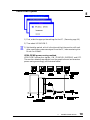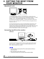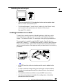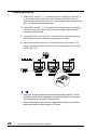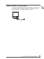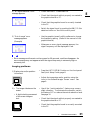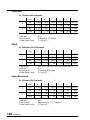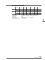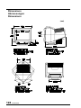
1
English
CONTENTS
PRECAUTIONS
i
INTRODUCTION
5
About This Manual ............................................... 5
Package Contents ............................................... 5
1 FEATURES
6
Features .............................................................. 6
Functions............................................................. 7
2 IMAGING ADJUSTMENT
9
- Screen menu Brightness, Contrast, Size, Position .................... 9
Geometry, Tilt, Bright Uniformity .......................... 9
Convergence ..................................................... 10
Moiré Reduction ................................................ 10
3 COLOR ADJUSTMENT
12
- Color menu Outline ............................................................... 12
Adjusting the Standard mode ............................ 13
Adjusting the Custom mode .............................. 14
4 POWER-SAVE SETUP
17
- PowerManager menu Set-up Procedure .............................................. 18
AutoPower Function .......................................... 21
For installation, see the ‘Quick Setup Guide’.
2
CONTENTS
5 OTHER SETTINGS
22
- Others, Information and Language menus Degaussing ....................................................... 22
Input Priority ...................................................... 23
Beep .................................................................. 24
Menu Position, Menu Contrast .......................... 24
Reset ................................................................. 24
Information status report ................................... 25
Language menu ................................................. 25
6 GETTING THE MOST FROM YOUR MONITOR
26
Adjustment Lock ............................................... 26
Connecting two PCs to the monitor ................... 26
Linking monitors in a chain ................................ 27
Optional i·Sound™ speaker system .................. 29
7 TROUBLESHOOTING
30
Troubleshooting ................................................. 30
8 CLEANING
37
9 SPECIFICATIONS
38
APPENDIX
123
CONTENTS
3
E
Copyright© 1999 by EIZO NANAO CORPORATION. All rights reserved. No part of
this manual may be reproduced, stored in a retrieval system, or transmitted, in any form
or by any means, electronic, mechanical, or otherwise, without the prior written
permission of EIZO NANAO CORPORATION.
EIZO NANAO CORPORATION is under no obligation to hold any submitted material
or information confidential unless prior arrangements are made pursuant to EIZO
NANAO CORPORATION's receipt of said information.
Although every effort has been made to ensure that this manual provides up-to-date
information, please note that EIZO monitor specifications are subject to change without
notice.
Apple and Macintosh are trademarks of Apple Computer Inc.,registered in the U.S. and other countries.
DPMS is a trademark and VESA is a registered trademark of Video Electronics Standards Association.
VGA is a registered trademark of International Business Machines Corporation.
ENERGY STAR is a U.S. registered mark.
Windows is a registered trademark of Microsoft Corporation in the USA and other countries.
ScreenManager, PowerManager, QuickSet and i·Sound are trademarks of EIZO NANAO CORPORATION.
FlexScan, SuperErgoCoat and EIZO are registered trademarks of EIZO NANAO CORPORATION.
4
CONTENTS
INTRODUCTION
About This Manual
This manual explains the precautions, features, specifications, and
operation of your EIZO monitor. The separately bound 'Quick Setup
Guide' explains how to install your monitor, and how to implement basic
adjustments with the ScreenManager utility.
Package Contents:
•
•
•
•
•
•
•
•
Monitor .................................................................. 1
Power Cord ............................................................. 1
Signal Cable (MD-C87) ......................................... 1
Cleaning Cloth for CRT Screen .............................. 1
User’s Manual ......................................................... 1
Quick Setup Guide ................................................. 1
Warranty Registration Card ................................... 1
EIZO FlexScan CRT Utility Disk ........................... 1
• If any of the above-listed items are missing or damaged, please
contact your local dealer for assistance.
• We recommend that you retain the original packing materials in case
of future need.
INTRODUCTION
5
E
1 FEATURES
Features
FlexScan® for wide compatibility
• 30 to 92 kHz horizontal scanning, 50 to 160 Hz vertical scanning with
automatic adjustment.
• The built-in microprocessor allows user-adjustable color control
adjustments to control screen distortion, and memorization of useradjusted settings.
• High resolution 1280 dots × 1024 lines with flicker free 85 Hz (Max.)
refresh rate.
High Resolution Color CRT
• 45 cm (17 inch) class, Actual Viewing Diagonal 40.5 cm (15.9 inches),
90° deflection, 0.25 mm screen pitch, high contrast, Aperture Grille
Type CRT.
• Dynamic Beam Spot Control (D.B.S.C.) systems achieve both
brightness and sharp focus over the entire screen.
• S/S DY (saddle/saddle deflection yoke) prevents interference between
two or more monitors that are close together (allow approximately
15 cm distance between the monitors to avoid interference).
Ecological & Ergonomic Design
• Anti-Reflective SuperErgoCoat® not only eliminates reflection of
ambient light, but also improves the focus level over the entire display
area, and reduces static electricity accumulation on the CRT surface.
• This model complies with TCO’ 99 (The Swedish Confederation of
Professional Employees) guidelines for low frequency electric fields,
magnetic fields, static electricity and visual ergonomic requirements.
Furthermore, this model is produced with concern for the
environment and contains no harmful substances in any of its
components.
• EIZO products conforms to the CE European directive which limits
EMI (Electromagnetic Interference) and EMS (Electromagnetic
Susceptibility/Immunity) and is unaffected by such fields created by
general office electrical equipment.
A declaration of conformity statement can be found at the end of this
manual.
6
1
FEATURES
Functions
E
Windows 95/98 Plug & Play ........ Readme.txt in the EIZO Utility
Disk
• This model complies with VESA DDC1/DDC2B standards and
supports the Plug & Play function proposed in Windows 95/98.
ScreenManager™ ........................ Quick Setup Guide & Pages 9-25
• ScreenManager allows the setting and adjustment of the displayed
image using the QuickSet™ Control Pad and intuitive graphic icons for
easy identification of each function.
Auto-Sizing Function ......................................... Quick Setup Guide
• The auto-sizing function lets the microprocessor calculate and
automatically adjust the screen size and position for the selected
display mode.
Customized Color Controls ................................................. Page 12
• Dynamic color control provides WYSIWYG (What You See Is What
You Get) color matching.
To meet individual preferences, two color modes are provided:
a Standard mode with selection of color temperature and a Custom
mode for adjustment of color tone.
PowerManager™ ................................................................... Page 17
• The PowerManager function automatically reduces unnecessary power
consumption when the monitor is not in active use. This function
complies with the NUTEK specification, the VESA DPMS system and
the EPA Energy Star Program1).
Input Priority ......................................................................... Page 23
• When dual inputs are used, this model has the capability for priority to
be given to one signal over the other, either the D-Sub or BNC video
input.
1) As an Energy Star Partner, EIZO NANAO CORPORATION has determined that this product meets
the Energy Star guidelines for energy efficiency.
1
FEATURES
7
Maintenance Port
• The monitor is equipped with a maintenance port on the rear panel.
This is provided so that complementary products can be utilized.
ScreenManager Pro, a utility software kit (supplied as optional), is
available which allows screen color, convergence and various geometric compensation adjustments to be made via a mouse through a serial
cable connected to the port and the PC.
Optional i·Sound™ speaker system .................................... Page 29
• The EIZO i·Sound speaker system is available as an option for
multimedia applications.
Please contact EIZO dealers for more information.
8
1
FEATURES
2 IMAGING ADJUSTMENT
- Screen menu -
E
All of the icons shown in the ScreenManager 'Screen' menu are described
below.
• Allow the monitor to stabilize for at least 30 minutes before making
image adjustments.
Brightness, Contrast, Size, Position
These functions are used to adjust the brightness, contrast, size and position
of the screen. For more information about how to adjust each of them,
please refer to the 'Quick Setup Guide', page 8.
Geometry, Tilt, Bright Uniformity
Image distortion, tilting and/or the imbalance of brightness over the entire
screen may be caused by the Earth's magnetic field. Use the 'Screen' menu’s
geometry (Side-Pincushion, Side-Pin Balance,
Trapezoidal, Parallelogram) adjustment function to correct any geometric distortion.
The tilt adjustment function adjusts both the image tilting and the bright
uniformity (the balance of brightness over the entire screen). For information about how to adjust them, please refer to the
Troubleshooting on page 33.
Image distortion, tilting and/or the imbalance of brightness may also be
caused by any device that generates a magnetic field. If the above
adjustments are not effective, try the following approaches.
• Check to see if there are any nearby interfering electronic devices such
as another monitor, an electric motor, or a speaker (other than an
optional EIZO i·Sound speaker unit). If so, move the device or move
the monitor.
• It is sometimes possible to correct distortion, tilting or the imbalance of
brightness by reorienting the monitor.
2
IMAGING ADJUSTMENT
9
Convergence
Displayed characters and images may appear fuzzy or have tinges of red,
green, or blue if the electron beams do not converge correctly. These can be
adjusted by the convergence adjustment feature in the ScreenManager.
What is convergence?
Convergence is the monitor’s ability to precisely illuminate specific
phosphors and line them up properly in order to produce pure color.
In order to properly adjust convergence, it is best to have an image that
makes it easy to see any convergence error. A black background with
white letters or lines is the best. This could be a DOS text mode or an
image created with a “paint” program.
When adjusting convergence, look at the adjustment across the whole
screen. When adjusting horizontal convergence, look at the left and right
edges of vertical lines or characters. When adjusting vertical
convergence, look at the top and bottom edges of horizontal lines or
characters. Proper adjustment is when the effect of red and blue tinges are
minimized.
• The convergence adjustment adjusts the entire screen. It is not
possible to limit adjustment to specific screen areas.
Moiré Reduction
What is moiré?
Moiré refers to an interference pattern of dark wavy lines on the screen.
It is not a defect, but rather an interference phenomenon caused by the
relationship between the phosphor layout and the imaging signal. Moiré
is often an indication of a good focus level. Moiré is particularly
noticeable when using a light-gray or every-other-dot pattern background. Although moiré can not be eliminated, it can be reduced with
the moiré reduction feature.
(Moiré)
10
2
IMAGING ADJUSTMENT
(Every-other-dot pattern)
Moiré can be reduced in a variety of ways.
E
1) Adjust with the ScreenManager’s moiré reduction function.
Adjust so that moiré becomes almost unnoticeable. Before adjusting, set
the desktop to an every-other-dot pattern (see picture, page 10) so that
moiré will be visible. Following the adjustment, change to a different
desktop background to reduce moiré even further.
2) Change the horizontal and vertical dimensions.
Adjust the horizontal and vertical dimensions of the display area as
necessary to reduce moiré.
3) Change the selected desktop or wallpaper pattern.
Use the PC software to change the desktop or wallpaper pattern. Any
solid color pattern is recommended. For detailed information on how to
change these patterns, refer to the documentation for the PC and
operating system.
• The screen image may shake slightly while the ScreenManager
moiré reduction function is ON. Switching the function OFF will
improve image stability and clarity at the expense of slightly greater
moiré.
2
IMAGING ADJUSTMENT
11
3 COLOR ADJUSTMENT
- Color menu -
Outline
EIZO monitors have incorporated two color adjustment mode, standard
and custom. The “Standard” mode allows the adjustment of the color
spectrum. The “Custom” mode allows extensive controls over the colors of
the displayed image on the screen.
All adjustments for either mode can be made quickly and easily through the
ScreenManager 'Color' Menu - offering a tool to create customized color
environment.
Please find the details of the color mode adjustment capabilities below:
Contents
Application
For routine work and
Standard mode
printing.
Sets color temperature.
Temperature can be set from 4000K to
10000K, in 500K increments. (Additionally,
industry standard of 9300K is set as default.)
Custom mode
Sets color temperature.
Allows for specific adjustments to Red,
Green and Blue (R/G/B). This consists of
the Cutoff and Gain functions.
For use when high
precision color
adjustment is necessary
(i.e. when there is a need
to obtain identical colors
on multiple monitors* or
match the display color
with printout color**.)
* The color adjustment spectrum may vary between monitors.
** A color calibrator can be used for even higher-precision color
adjustment.
• Each monitor is slightly different, if two monitors are set to the same
color temperature value (i.e. 6500K), they may not necessarily look
the same.
12
3
COLOR ADJUSTMENT
Adjusting the Standard mode
E
Color
Temprature
• Users should allow at least 30 minutes for the monitor to stabilize
before setting the color adjustments or color matching.
Procedure
1) Go to the 'Color' menu.
2) Select the “Standard mode” setting from the 'Color mode' menu.
3) Select the 'Temperature' icon. A color temperature bar will appear.
4) Adjust the temperature by using the right or left Arrow keys.
5) Press the ENTER key to save the data.
What is color temperature?
Color temperature is a method to measure the white color tone,
generally indicated in degrees Kelvin. At high temperatures the white
tone appears somewhat blue, while at lower temperatures it appears
somewhat red. Computer monitors generally give best performance at
high temperature settings.
5000K: Slightly reddish white. Often used in printing industry.
6500K: Warm-white tone, similar to white paper or daylight. This
temperature is good for video-image display.
9300K: Slightly bluish white. This is the default setting for your
EIZO monitor.
3
COLOR ADJUSTMENT
13
Adjusting the Custom mode
Cutoff and Gain adjustments
Monitors use red, green and blue (R, G, and B) to convey color
information. They use an additive method to combine different
amounts of the primary colors to produce a desired color. In other
words, monitors start with no light (black) and add percentages of red,
green and blue to make colors. White is usually produced by adding the
same amount of all three colors, where black is usually produced by
adding no color.
However, colors are not only determined by the balance but also the
intensities of R, G, and B (how bright they are) which we call Gain, and
the saturation of R, G and B (how vivid or dull they are) which we call
Cutoff.
• Users should allow at least 30 minutes for the monitor to stabilize
before setting the color adjustments or color matching.
• Before you attempt to change the colors, always start with the color
settings set to the "default settings" by using the 'Reset' function in
the ScreenManager 'Others' menu.
• If only a quick setting is required, that is close to the desired color,
but not exact, skip making any changes to the Cutoff adjustment
(step 4). If a precise match is desired, adjustment of the Cutoff
levels must be made. We recommend that for exact matching, use a
color calibrator.
Procedure
1) For optimum results, before beginning the custom color adjustment,
go to the 'Screen' menu and set the display to maximum brightness
and contrast. (Use the 'Screen' menu’s 'Brightness' and 'Contrast'
icons.)
2) Then, return to the 'Color' menu and select the 'Custom mode'
setting.
3) Set the color temperature.
14
3
COLOR ADJUSTMENT
a) Select the 'Temperature' icon from the sub menu.
b) Select the temperature as desired by moving the arrow keys in
any direction.
4) Adjust the Cutoff
Cutoff
The Cutoff adjustment is the most powerful adjustment. It alters
the starting point (the black level) and the ending point (the white
level). If the Cutoff level for color is raised or lowered, black,
white, and all levels between are raised or lowered by the same
degree.
Before adjusting the Cutoff, it is best to display a screen with a black
background (such as the DOS command screen).
a) Select 'Cutoff' icon. The screen shown on the left will appear.
b) Adjust each color until you can create a uniform black screen.
5) Adjust the Gain
Gain
The Gain adjustment has no effect on the starting point (the black
level). It changes only the ending point (the white level). The Gain
adjustment is used to fine tune the whites and light grays to a good
balance.
Before adjusting the Gain, it is best to display a screen image that has
a white or grayscale background, such as the operating window for
Windows.
a) Select 'Gain' icon. The screen shown on the left will appear.
b) Adjust each color until you can create a uniform white screen.
6) To register the adjustment, select the "Save" icon and then press the
ENTER key. If the settings are not saved, all adjustments will be lost.
7) Finally, readjust the contrast in the 'Screen' menu to get the best
image clarity.
• If an inappropriate adjustment is made, corrections can be made by
repeating the above procedure starting from Step 3 (temperature
setting).
• The values shown in percentages (%) for both the Cutoff and Gain
adjustments represent the current level within the specific adjustment only. They are available only as a reference tool. (To create a
uniform white or black screen, the percentages for each will probably
not be the same.)
3
COLOR ADJUSTMENT
15
E
• These diagram explains how the color curves were changed for the
best adjustment in steps 4 and 5.
Adjust the black level
so that the low end of
the curve for each
color (R,G,B) is equal
as see picture 2.
Adjust the white level so
that the high end of the
curve for each color
(R,G,B) is equal as see
picture 3.
This setup gives the best
color balance.
What is the relation between the color and the brightness adjustment?
Brightness uniformly adjusts the amount of light output for the entire
screen and its background. If it is increases too high the background
will become white, too low and many dark colors will not be displayed.
It affects all color controls.
Contrast varies the difference in light output from the lowest to the
highest screen intensities. It is the brightness adjustment for the video
signal area.
After making the color settings, readjust the contrast to get the best
definition and intensity of the colors for the displayed image.
16
3
COLOR ADJUSTMENT
4 POWER-SAVE SETUP
- PowerManager menu -
E
What is PowerManager?
The PowerManager feature automatically reduces the monitor’s power
consumption during idle periods, in accordance with the PCs
ScreenSaver software.
There are two PowerSaving modes in the EIZO PowerManager:
Mode 1 and Mode 2. Even if the monitor is in a power saving mode,
it will return to a normal display immediately when the mouse or
keyboard is operated.
The EIZO PowerManager functions comply with NUTEK, the VESA
DPMS standard, and the EPA’s Energy Star guidelines.
Power consumption:
In operation: up to 135 W (Max.)
PowerManager Mode 1: less than 10 W
(Power Indicator flashing green)
PowerManager Mode 2: less than 5 W
(Power Indicator solid yellow)
• Do your part to conserve energy, turn off the monitor when your
finished using it. Complete energy use can only be stopped by
disconnecting the monitor from the power supply.
• When the monitor is in a power saving mode, the optional EIZO
i·Sound speaker unit will turn off.
4
POWER-SAVE SETUP
17
Set-up Procedure
Set the monitor’s power-save environment to match the PC’s ScreenSaver
software.
• For the PC setup, please refer to the user’s manuals for the PC and
graphics board.
There are two power-save settings for the monitor.
‘VESA DPMS’ system works with the VESA DPMS signal.
‘NUTEK’s system works with a screen saver software and Energy Saver
for Macintosh which blanks the screen (totally black screen).
Set the monitor to match the PC’s power-saving software, as follows.
Monitor setting for matching the PC:
PC
PC Power saving
Monitor setting
PC/AT and compatibles
(VESA DPMS activated)
VESA DPMS (Signal)
VESA DPMS
PC/AT and compatibles
Windows
(VESA DPMS
(Control Panel/Desktop/
inactivated)
ScreenSaver: "Blank Screen"
Macintosh
Energy Saver
ScreenSaver software
After Dark/"Blank" settings
18
4
POWER-SAVE SETUP
NUTEK
NUTEK
NUTEK
VESA DPMS System
E
1) First, make the appropriate settings for the PC. (See note, page 18.)
2) Then select 'VESA DPMS'.
3) Set the delay period, which is the interval that the monitor will wait
after receiving a power-save signal from the PC, before entering into
Mode 1 or Mode 2.
VESA DPMS power-saving method
VESA DPMS utilizes four signals: ON, STANDBY, SUSPEND, and OFF.
The monitor detects these signals from the graphics board and executes
power-saving accordingly, as illustrated below.
4
POWER-SAVE SETUP
19
NUTEK System
1) First make the appropriate ScreenSaver settings (Macintosh/Energy
Saver) for the PC.
2) Then select 'NUTEK'.
3) Set the delay time, which is the interval between the time that the
ScreenSaver (Macintosh/EnergySaver) blanks the screen and the time
that the monitor enters Mode 1.
4) Set the Mode 1 duration time which is the user definable time (0-60
minutes) before the monitor enters Mode 2.
NUTEK power-saving method
Mode 1 operates for a user-definable period in ‘Duration’ (in 0-60
minutes) before the monitor enters Mode 2. If the keyboard or the mouse
are not in use during this period, the monitor will then enter
PowerManager Mode 2.
20
4
POWER-SAVE SETUP
What is VESA DPMS?
E
The acronym VESA stands for “Video Electronics Standards
Association,” and DPMS stands for “Display Power Management
Signaling.” DPMS is a communication standard that PCs and
graphics boards use to implement power savings at the monitor side.
What is NUTEK?
NUTEK is the acronym for the Swedish National Board for Industrial
and Technical Development, an organization that works to promote
power-saving technologies.
What is Energy Star?
“Energy Star” is a set of power-saving guidelines issued by the U.S.
Environmental Protection Agency (EPA). The guidelines apply to PC
systems and peripherals.
4
POWER-SAVE SETUP
21
5 OTHER SETTINGS
- Others, Information and Language
menus -
All of the icons shown in the ScreenManager 'Others' menu are described
below.
Degaussing
The monitor automatically degausses every time the power is turned ON
and every time it is reactivated from the PowerManager power-saving
Mode 2. A degaussing function is provided in the ScreenManager for use
at other times. Note that the image vibrates slightly while degaussing is in
progress, but will return to normal when degaussing is completed.
• The degauss circuitry takes about 30 minutes to regain maximum
power following degaussing before it can work again.
What is degaussing?
“Degaussing” refers to the process of removing magnetic-field effects
from the monitor. Operation of the monitor within a magnetic field
may adversely effect color purity. Degaussing can be used to correct
the problem.
22
5
OTHER SETTINGS
Input Priority
This unique feature of the ScreenManager is for those users who utilize
two PCs. It allows the user to set the priority on the PC of choice.
The monitor automatically detects the selected 'Input Priority' setting
every time the power is turned ON (see note). Once the priority is set,
whenever a signal is detected at that connection, the monitor will convert
to that signal and display the data being sent.
There are three settings available: D-Sub, BNC or Manual. Since the
monitor comes with a standard D-Sub cable, the default priority setting
is set to D-Sub.
If only a single PC is connected and the standard bundled cable is used,
no special setting is required.
How to use
Use this function to select which of two connected PCs controls the
monitor. The following table indicates the available selections. For
additional information, refer to "Getting the Most from your Monitor"
on page 27.
Priority setting
Performance
D-Sub
The monitor automatically detects and displays
signals received from the D-Sub or BNC input.
If signals from both inputs are present, the monitor
displays the D-Sub signal.
BNC
The monitor automatically detects and displays input
signals received at the BNC or D-Sub input.
If signals from both inputs are present, the monitor
displays the BNC signal.
Manual
The monitor does not detect signals automatically.
Select the active input by pressing the BNC/D-Sub
selection button on the monitor's front panel.
• The ScreenManager priority setting can be overridden at any time by
using the BNC/D-Sub selection button on the front panel. Priority
selection will be restored when the PC or monitor is switched ON
again.
5
OTHER SETTINGS
23
E
Beep
Use this feature to set the beeper ON or OFF. If the beeper is ON, the
monitor will generate beep signals as shown below. If the beeper is OFF,
the monitor will not beep.
Short beep
• ScreenManager item selected.
• ScreenManager parameter adjusted to minimum
or maximum limit.
• BNC/D-Sub selection button pressed.
Long beep
• AUTO-SIZING button pressed.
• ScreenManager data-save executed.
Four short beeps
• Monitor not connected correctly.
• PC turned off.
• Monitor received unsupported signal frequency.
Menu Position, Menu Contrast
Use these functions to adjust the position, contrast and brightness of the
ScreenManager menu. When adjusting color, it is useful to adjust the
contrast and brightness of the ScreenManager menu according to the
background.
Reset
Use this function to return all ScreenManager parameters (size, position,
geometry, color, PowerManager etc.) to their factory default settings.
Default settings are as follows.
•
•
•
•
Screen:
Color:
PowerManager:
Others:
• Language:
24
5
OTHER SETTINGS
Moiré = OFF
Standard/9300K
VESA
Input Priority = D-Sub
Beep = ON
English
Information status report
E
Use this feature to review the current ScreenManager settings. The menu
contains four pages. Pressing the ENTER key selects the different pages
in order. The information displayed on each page is as follows.
• Page 1: Input port, horizontal and vertical frequencies, moiré
reduction setting
• Page 2: Color-adjustment settings
• Page 3: PowerManager settings
• Page 4: Input priority (see note), and beep settings
• The current ScreenManager setting is displayed even if the input
selection has been manually overridden by the use of the
BNC/D-Sub selection button.
Language menu
Use this menu to select the ScreenManager language. Six languages are
available to choose from: English, German, French, Spanish, Italian and
Swedish. The menu text will appear in the language that is selected here.
5
OTHER SETTINGS
25
6 GETTING THE MOST FROM
YOUR MONITOR
Adjustment Lock
The ScreenManager operation can be disabled by holding down the
AUTO-SIZING button while switching on the monitor’s power. This will
disable (“lock”) the ScreenManager and AUTO-SIZING button,
protecting from accidental changes. To unlock the buttons: switch the
power off, then hold down AUTO-SIZING button once again and turn
the power back on.
Note that brightness and contrast can be adjusted using the short cut
keys (see Quick Setup Guide page 6) even while the Control pad is
locked. After making such an adjustment, push the ENTER key to clear
the brightness/contrast adjustment menu from the screen. Also, the
BNC/D-Sub Selection button can still be used.
Connecting two PCs to the monitor
(Example)
MD-C53A (optional)
Connect one PC to the monitor’s D-Sub connector and another to the
BNC connector. The BNC connection should be made with an EIZO
BNC cable, available as an option.
• Be sure that the monitor and the PC are both switched off before
connecting them.
• Be sure to connect the cable securely.
• Contact EIZO dealers for information about optional cables.
26
6
GETTING THE MOST FROM YOUR MONITOR
Selecting the active input
E
• The front panel’s BNC/D-Sub selection button can be used to select
BNC or D-Sub as the active input.
• The ScreenManager’s “Input Priority” setting (in the 'Others' menu)
can be used to set up the automatic selection of the input .
See page 23 for details.
Linking monitors in a chain
Three to four monitors can be chained together so that they can be
controlled from a single source. All monitors will display the same
image. This feature is useful, for example, when giving a presentation.
The connection is made through the BNC inputs. Specifically, you
attach BNC coaxial “Y” connectors to the BNC inputs on each monitor.
Then connect the BNC signal cables. Please make sure the termination
switch on each monitor is set appropriately, as described in the chaining
procedure.
• Any EIZO monitor with a termination switch can be added to the
chain.
• In order to maintain image clarity, the total length of chained cables
should not exceed approximately 8 m (about three to four chained
monitors).
• Termination switches are effective only with BNC connections.
• If a video color printer is included in the configuration, it should be
placed at the end of the chain.
6
GETTING THE MOST FROM YOUR MONITOR
27
Chaining procedure
1) Attach BNC coaxial “Y” connectors to each of the BNC inputs (H, V,
G, R and B) on the first monitor in the chain (call this Monitor A).
Then connect the monitor to the PC, using a signal cable equipped with
BNC connectors at the monitor side.
2) Attach BNC coaxial “Y” connectors to the next monitor (monitor B).
Connect monitors A and B, this time using a signal cable with BNC
connectors at both sides.
3) Connect monitor B to monitor C, and continue in the same manner
until all the monitors have been connected in the chain.
4) Set the termination switch on the last monitor in the chain to 75
ohms. Set the termination switches on all other monitors to HIGH
IMPEDANCE (∞).
• Use a pen or other implement to set the termination switch. Do not
push the switch with a screwdriver or other hard object, as this may
cause damage to the switch or the monitor.
• When returning to a one-monitor configuration, be sure to reset the
termination switch on the monitor to 75 ohms.
28
6
GETTING THE MOST FROM YOUR MONITOR
Optional i·Sound™ speaker system
The optional speaker system i·Sound connects directly to the monitor and
can be used to support multimedia applications. The speaker also has a
microphone function. For details, consult EIZO dealers.
6
GETTING THE MOST FROM YOUR MONITOR
29
E
7 TROUBLESHOOTING
Troubleshooting
This page presents problems that can be corrected by the user. If a
problem persists even after applying the suggested remedies, contact an
EIZO dealer.
Problems
Points to check with possible
solutions
Problems caused by
incorrectly setting of the
termination switch.
1) Misconvergence of colors.
2) Focus is dull.
3) PowerManager does not
work properly in VESA
setting.
4) Slight shadow appears on the
edges of the screen image or
text. (only for the BNC
connections.)
• The termination switch on the rear of the monitor
should be set to 75 Ω position (default) for
connection to a single monitor.
If it is set to the ∞ position when using a single
monitor, some problems like 1) ~ 4) may occur.
Check that the switch position is set to 75 Ω
position.
No picture
1) Indicator status: OFF
• Check that the power cord is correctly connected.
2) Indicator status: GREEN
• Try pressing a key on the keyboard, or clicking the
mouse. (The screen-saver software may be active.)
• Check brightness and contrast settings. Minimum
settings will cause screen to be blank.
3) Indicator status: YELLOW
• Try pressing a key on the keyboard, or clicking the
mouse. (The screen-saver software may be active.)
If the problem persists, switch off the monitor power
for a few minutes, then switch it back on and try
again.
30
7
TROUBLESHOOTING
4) “No signal detected” error
message appears.
• Check that the PC is switched ON.
• Check that the signal cable is properly connected to
the graphics board or PC.
• Check that the graphics board is correctly inserted
in the PC.
• Switch the signal input by pushing the BNC/ D-Sub
selection button on the front control panel.
5) “Out of range” error
message appears.
(Example)
• Use the graphics board’s utility software to change
the frequency setting. (Refer to the manual of the
graphics board.)
• Whenever an error signal message appears, the
signal frequency will be displayed in red.
• Error messages will remain on the screen for 30 seconds, and then disappear. An
error message may not appear at all if the signal frequency is extremely high or
extremely low.
Imaging problems
1) Display size and/or position
is incorrect.
• Press the AUTO-SIZING button on the front panel.
See Quick Setup Guide, page 8.
• Adjust the image size and/or position using the
icons in the ScreenManager 'Screen' menu. See
page 9.
2) • The image vibrates on the
screen.
• A slight shaking movement
of the screen image or
text.
• Use of the “moiré reduction” feature may cause a
slight vibration. To eliminate the vibration, switch
the feature OFF or reduce the moiré reduction level.
See page 10.
• Check that the signal cable is properly connected to
the graphics board or PC.
• Check that the graphics board is correctly mounted
in the PC.
7
TROUBLESHOOTING
31
E
• The signal cable might be damaged. Please contact
the dealer.
• The monitor may be located close to a device that is
generating a magnetic field. Such devices include
speakers (other than the EIZO optional i·Sound
speaker), electric motors, high-voltage cables, and
other monitors. It may be solved by switching off
or moving the interfering device, or by relocating
the monitor.
• If the volume level of the EIZO optional i·Sound
speaker is too high, it may, in some cases, cause a
slight vibration. To eliminate, turn down the
volume of the speaker.
• A unstable signal from the graphics board may be the cause of the above problem
when using the monitor with a high resolution or in a high refresh mode. (The video
signal from the graphics board might be made irregular due to the use of a high
speed dot clock.) Change the resolution or the refresh rate to another setting.
3) The image has a background
shadow.
• Try adjusting the convergence in the
ScreenManager’s Screen menu.
See page 10.
• This problem can occur when using BNC
connection and the termination switch is set
incorrectly. The termination switch should be set to
75 ohms for a connection to a single monitor.
See page 27.
4) The image is flickering.
32
7
TROUBLESHOOTING
• Flicker will occur with interlaced scanning, or
non-interlaced scanning with a low refresh rate. All
EIZO monitors are capable of reproducing high
refresh rates for non-interlaced scanning. If a
problem occurs when using a non-interlaced signal,
try adjusting the graphics board to increase the
refresh rate (if possible). Refer to the graphics
board manual for information.
Non-Interlaced / Interlaced
E
In a “non-interlaced” scan, the electric guns draw the entire image in one vertical
pass, with each pass covering every horizontal line.
In a “interlaced” scan, the guns draw the entire image by scanning vertically twice.
At the first scanning, the guns draw every other horizontal line. At the second, they
draw the other lines. Thus, in a "interlaced scan", the image flickers more visibly
when compared with a "non-interlaced" scan.
Flicker
The term “flicker” refers to noticeable shimmering that occurs when the image on
the screen is redrawn (“refreshed”) too slowly. A refresh rate of 80 Hz means the
image is redrawn 80 times per second. Most people will notice flicker at image
refresh rates as high as 60 or 70 Hz, whereas refresh rates of 72 Hz or above usually
is not noticeable. Flicker is known to be the cause of visual fatigue.
5) The screen is too bright or too
dark.
• Adjust the contrast and brightness using the
ScreenManager’s Screen menu.
See page 9.
6) The screen is partly dark.
• The CRT is not warmed up. Allow 30 minutes for
the monitor to stabilize.
• This problem can be caused by earth magnetism. If
this condition is noticeable, please follow the
procedure below.
(Procedure)
1) Degauss the screen by using the "Degaussing"
feature in the ScreenManager's 'Others' menu.
2) Select the "Tilt" function through the
ScreenManager's 'Screen' menu.
3) Adjust the screen for the best balance between
bright uniformity and tilt compensation.
4) If after performing the above adjustment the
vertical sides of the screen image may be at a
slight angle, this can be corrected by using the
"Parallelogram" adjustment in the
ScreenManager's 'Screen' menu.
7) Moiré patterns are
distracting.
• Go to the ScreenManager’s Screen menu. Switch
on the moiré reduction feature and adjust as
necessary.
See page 10.
7
TROUBLESHOOTING
33
Color problems
1) The entire screen appears
bluish or reddish.
• The CRT is not warmed up. Allow 30 minutes for
the monitor to stabilize.
2) Color purity is not uniform.
• Allow 30 minutes for the monitor to warm up.
• Degauss the screen. (Use the degaussing feature in
the ScreenManager’s 'Others' menu. See page 22.)
3) Misconvergence of colors.
(red, green, blue)
• Allow 30 minutes for the monitor to warm up.
• Adjust the convergence using the Convergence
feature in the ScreenManager’s Screen menu.
See page 10.
• This problem can occur when using a BNC
connection and the termination switch is set
incorrectly. The termination switch should be set
to 75 ohms for connection to a single monitor.
See page 27.
Explanation of the Characteristics of CRTs
When the monitor is not fully warmed up, the screen may look slightly colored, e.g.
reddish or bluish. This phenomenon is due to the unstableness of the electron gun
during its warm-up period. Please wait for about 30 minutes until the monitor
stabilizes in order to gain its proper color.
Others
1) The monitor beeps or hums.
• The monitor emits a humming noise when
executing automatic degaussing at power-ON.
This is not a problem.
• The monitor beeps at any time. This is not a
problem. See page 24 for full details.
34
7
TROUBLESHOOTING
2) Control Pad “ENTER key”
does not operate.
• The Adjustment Lock is probably on. To unlock:
switch off the monitor power, then hold down the
AUTO-SIZING button and switch the monitor
back on. See page 26.
3) AUTO-SIZING button does
not operate.
• The Adjustment Lock is probably on. To unlock:
switch off the monitor power, then hold down the
AUTO-SIZING button and switch the monitor
back on. See page 26.
4) AUTO-SIZING button does
not work properly.
• The Auto-sizing function is intended for use on the
Macintosh and on IBM compatibles running
Windows. It may not work properly if either of the
following applies.
- You are running an AT-compatible PC on
MS-DOS (not Windows).
- The background color for the “wallpaper” or
“desktop” pattern is set to black.
• Some signals from graphics boards may not
function properly.
• A solid-color screen (i.e. red, green, blue) may appear for an instant while performing
the auto-sizing function, this phenomenon is not a failure.
5) Characters are too large.
• Change the resolution of the graphics board to a
higher setting. (Refer to the manual for the graphics
board or PC.)
What is Resolution?
Resolution is expressed as the number of dots (pixels) displayed on the screen. A
larger number of dots produces a more sharply defined (a higher-resolution) image.
Note that for a given screen size the dot size decreases as the number of dots
increases: a 640 × 480 (dot × line) resolution uses larger pixels than a 1024 × 768
resolution. The display size of a given font therefore varies according to the
resolution. Higher resolutions allow you to display more information on the screen.
7
TROUBLESHOOTING
35
E
Changing the resolution
If you are using a Macintosh, you can change the resolution from the APPLE menu by
selecting “Option” from “Monitor” or “Sound & Display.” If you are using a PC other
than a Macintosh, refer to the manual for your PC or graphics board for information.
Please refer to both the graphics board and monitor manuals for the scanning frequency
compatibility.
6) Two horizontal hairlines are
visible on the screen.
• These are dampening wires. Dampening wires are
used to support the CRT’s aperture grille, and are
visible as thin dark lines across the screen. All
EIZO aperture-grille type CRTs include two such
horizontal wires.
The aperture grille itself is a grid of taut metal
filaments that spans the entire screen from top to
bottom.
7) Faint black vertical lines are
visible on the screen.
• The aperture grille may be misaligned. Shock or
vibration during transport may, in some cases,
cause the aperture grille to fall out of alignment.
The problem will appear as one or more faint black
lines across the screen.
If this problem occurs, it may be able to solved by:
• degaussing the screen, or
• lightly tapping (do not hit) the side of
the monitor.
If neither of these methods works, try executing the
following procedure.
1) Display a bright white field over the area where
the black line(s) appear, with a black field over
the unaffected areas. (Do this by opening a
bright-white window on top of a black desktop
or wallpaper background. Position the window
so that it just covers the area of misalignment.)
2) Set brightness and contrast to maximum values,
and keep the display ON until the problem is
corrected. Try tapping the side of the display
lightly to help expedite realignment. The white
field will heat up the misaligned area of the grille,
returning it to proper alignment.
36
7
TROUBLESHOOTING
8 CLEANING
WARNING
E
• Keep liquids away from the monitor.
Spillage into the cabinet may result in fire, electric shock, or
equipment damage.
If an object or liquid falls/spills into the cabinet, unplug the monitor
immediately. Have the unit checked by a qualified service engineer
before using it again.
Using the monitor in this condition could cause serious injury or
equipment damage.
CAUTION
• To ensure safety, always unplug the monitor before cleaning it.
Failure to do so may result in electric shock.
• Periodically clean the area around the plug.
Buildup of dust, water, or oil on the plug may result in fire.
• Never use thinner, benzene, or other strong solvents or abrasive
cleaners, as these may cause damage to the cabinet or CRT.
• Dust accumulation within the monitor may result in fire or
equipment failure. Please keep the monitor in a dust-free
environment.
Periodic cleaning is recommended to keep the monitor looking new and
to prolong its operational lifetime. Clean the cabinet and CRT areas as
follows.
Cabinet
To remove stains, wipe the cabinet with a soft, lightly moistened cloth
using a mild detergent. Do not spray wax or cleaner directly onto the
cabinet. Do not clean with compressed air.
CRT Surface
The monitor comes with a special cloth specifically designed to remove
fingerprints and dust from the screen. The cloth is washable, and will
remain effective regardless of the number of times it is washed. If the
supplied cloth is not available, you can clean the CRT surface with
gauze, cotton, or lens paper.
If necessary, stubborn stains can be removed by moistening part of a
cloth with water or alcohol (ethanol, methanol, or isopropyl alcohol) to
enhance its cleaning power.
8
CLEANING
37
9 SPECIFICATIONS
Electrical Specifications
CRT AG Pitch
CRT Size
CRT Surface
Scan Frequency
Horizontal:
Vertical:
Max. Active Display Area
Power Supply
Power Consumption
Normal:
Max.:
PowerManager Mode 1:
PowerManager Mode 2:
Input Connector
Display Colors
Recommended Resolution
Input Signal
Sync:
Video:
0.25 mm (Aperture Grille)
45 cm (17 inch) class
90° deflection Aperture Grille type
Anti-Reflective SuperErgoCoat®
30 kHz-92 kHz (Automatic)
50 Hz-160 Hz (Automatic)
326 mm (H) × 241 mm (V) (Diagonal: 405 mm)
* Display size can be set by the user through
microprocessor control panel.
* The actual size displayed can be dependent on the
graphics board or PC utilized.
220-240 VAC±10%, 50 Hz, 0.8 A
115 W
135 W (EIZO optional speaker attached: 138 W)
Less than 10 W
Less than 5 W
D-Sub mini 15-pin and
BNC × 5 (H(H/V), V, G, R, B, ) (switchable)
Unlimited Colors
1280 dots × 1024 lines
• H/V Separate, TTL, Positive/Negative
• H/V Composite, TTL, Positive/Negative
• H/V Composite, Sync on Green 0.3 Vp-p,
Negative
• RGB Separate, Analog 0.7 Vp-p/75 Ω, Positive
• RGB Separate, Analog plus Composite Sync on
Green
Mechanical Specifications
Dimensions
Weight
410 mm (W) × 413 mm (H) × 439 mm (D) (net)
529 mm (W) × 537 mm (H) × 597 mm (D) (gross)
21.0 kg (net), 25.0 kg (gross)
Environmental Specifications
Temperature
Humidity
38
9
SPECIFICATIONS
operating: 0°C to 40°C
storage: -20°C to 60°C
30% to 80% R.H. Non-condensing
APPENDIX
Pin Assignment
Pin-Belegung
Affectation des Broches
D-Sub mini 15 pin connector
Pin No.
Signal
Pin No.
Signal
1
Red video
9
No pin
2
Green video
10
Ground
3
Blue video
11
(shorted)
4
Ground
12
Data
5
No pin
13
H. Sync
6
Red ground
14
V. Sync
7
Green ground
15
Clock
8
Blue ground
BNC connector
Connector
Input signal
Sync on green
H. SYNC
V. SYNC
GREEN
RED
BLUE
N/A
N/A
GREEN
Composite
sync
RED
BLUE
N/A
GREEN
RED
BLUE
TTL
V. SYNC
GREEN
RED
BLUE
TTL H/V
Composite sync composite
sync
Separate sync
124
APPENDIX
TTL
H. SYNC
Preset Timing Chart
Timing-Übersichten
Synchronisation des Signaux
Based on the signal diagram shown below, 4 factory presets have been
registered in the monitor's microprocessor.
Der integrierte Mikroprozessor des Monitors unterstützt 4 werkseitige
Standardeinstellungen (siehe hierzu die nachfolgenden Diagramme).
4 signaux ont été enregistrés en usine dans le microprocesseur du moniteur,
conformément au diagramme de synchronisation ci-dessous.
A
A
Front Porch
Vordere Schwarzschulter
Front avant
B
Sync Period
Synchronimpuls
Délai de
synchronisation
C
Back Porch
Hintere Schwarzschulter
Front arrière
D
Blanking Period
Austastzeit
Délai de clignotement
E
Display period
Display-Zeit
Délai d'affichage
F
Total cycle
Kompletter Zyklus
Cycle total
S
Sync signal level
Sync-Signalpegel
Niveau du signal de
synchronisation
V Video signal level
Video-Signalpegel
Niveau du signal vidéo
The sync pulse, for both the horizontal and vertical signals, has positive or
negative polarity combination (as shown following) to encode different
modes.
Der Sync-Impuls für Horizontal- und Vertikalsignale weist eine
kombinierte (d. h. eine positive und negative) Polarität auf (siehe unten).
Auf diese Weise ist eine Codierung der verschiedenen Betriebsarten
möglich.
L’impulsion de synchronisation, pour les signaux horizontaux et verticaux,
a une combinaison de polarités positives ou négatives (présentée page
suivante) qui permet de coder différents modes.
APPENDIX
125
VGA (text)
n 720 dots × 400 lines mode
Unit
µs
H
V
A
B
C
D
E
F
0.636
3.813
1.907
6.356
25.422
31.778
Dot
18
108
54
180
720
900
ms
0.381
0.064
1.111
1.556
12.712
14.268
12
2
35
49
400
449
Line
Frequencies:
Interlace:
Sync Polarity:
Video Signal Level:
fd/28.322 MHz, fH/31.468 kHz, fV/70.087 Hz
Non
H/Negative, V/Positive
0.7 Vp-p/75 Ω
VESA
n 1280 dots × 1024 lines mode
Unit
µs
H
V
A
B
C
D
E
F
0.305
1.016
1.524
2.844
8.127
10.971
Dot
64
160
224
448
1280
1728
ms
0.011
0.033
0.483
0.527
11.235
11.761
1
3
44
48
1024
1072
Line
Frequencies:
Interlace:
Sync Polarity:
Video Signal Level:
fd/157.50 MHz, fH/91.15 kHz, fV/85.02 Hz
Non
H/Positive, V/Positive
0.7 Vp-p/75 Ω
Apple Macintosh
n 832 dots × 624 lines mode
Unit
H
V
µs
APPENDIX
B
0.559
C
1.117
D
3.910
5.586
E
F
14.524
20.111
Dot
32
64
224
320
832
1152
ms
0.020
0.060
0.784
0.865
12.549
13.414
1
3
39
43
624
667
Line
Frequencies:
Interlace:
Sync Polarity:
Video Signal Level:
126
A
fd/57.28 MHz, fH/49.73 kHz, fV/74.55 Hz
Non
Separate sync, TTL, Negative
0.7 Vp-p/75 Ω
n 1152 dots × 870 lines mode
Unit
H
V
µs
A
B
0.320
C
1.280
D
1.440
3.040
E
F
11.520
14.560
Dot
32
128
144
304
1152
1456
ms
0.044
0.044
0.568
0.655
12.667
13.322
3
3
39
45
870
915
Line
Frequencies:
Interlace:
Sync Polarity:
Video Signal Level:
fd/100 MHz, fH/68.68 kHz, fV/75.06 Hz
Non
Separate sync, TTL, Negative
0.7 Vp-p/75 Ω
A
APPENDIX
127
Dimensions
Abmessungen
Dimensions
(mm)
128
APPENDIX
Congratulations!
You have just purchased a TCO’99 approved and labelled product! Your choice has provided you
with a product developed for professional use. Your purchase has also contributed to reducing the
burden on the environment and also to the further development of environmentally adapted
electronics products.
Why do we have environmentally labelled computers?
In many countries, environmental labelling has become an established method for encouraging the adaptation of goods and services to the environment. The main problem, as far as
computers and other electronics equipment are concerned, is that environmentally harmful
substances are used both in the products and during their manufacture. Since it is not so far
possible to satisfactorily recycle the majority of electronics equipment, most of these potentially
damaging substances sooner or later enter nature.
There are also other characteristics of a computer, such as energy consumption levels, that are
important from the viewpoints of both the work (internal) and natural (external) environments.
Since all methods of electricity generation have a negative effect on the environment (e.g. acidic
and climate-influencing emissions, radioactive waste), it is vital to save energy. Electronics
equipment in offices is often left running continuously and thereby consumes a lot of energy.
What does labelling involve?
This product meets the requirements for the TCO’99 scheme which provides for international
and environmental labelling of personal computers. The labelling scheme was developed as a
joint effort by the TCO (The Swedish Confederation of Professional Employees), Svenska
Naturskyddsforeningen (The Swedish Society for Nature Conservation) and Statens
Energimyndighet (The Swedish National Energy Administration).
Approval requirements cover a wide range of issues: environment, ergonomics, usability,
emission of electric and magnetic fields, energy consumption and electrical and fire safety.
The environmental demands impose restrictions on the presence and use of heavy metals,
brominated and chlorinated flame retardants, CFCs (freons) and chlorinated solvents, among
other things. The product must be prepared for recycling and the manufacturer is obliged to
have an environmental policy which must be adhered to in each country where the company
implements its operational policy.
The energy requirements include a demand that the computer and/or display, after a certain
period of inactivity, shall reduce its power consumption to a lower level in one or more stages.
The length of time to reactivate the computer shall be reasonable for the user.
Labelled products must meet strict environmental demands, for example, in respect of the
reduction of electric and magnetic fields, physical and visual ergonomics and good usability.
Below you will find a brief summary of the environmental requirements met by this product.
The complete environmental criteria document may be ordered from:
TCO Development
SE-114 94 Stockholm, Sweden
Fax: +46 8 782 92 07
Email (Internet): [email protected]
Current information regarding TCO’99 approved and labelled products may also be
obtained via the Internet, using the address: http://www.tco-info.com/
Environmental requirements
Flame retardants
Flame retardants are present in printed circuit boards, cables, wires, casings and housings.
Their purpose is to prevent, or at least to delay the spread of fire. Up to 30% of the plastic in a
computer casing can consist of flame retardant substances. Most flame retardants contain
bromine or chloride, and those flame retardants are chemically related to another group of
environmental toxins, PCBs. Both the flame retardants containing bromine or chloride and the
PCBs are suspected of giving rise to severe health effects, including reproductive damage in fisheating birds and mammals, due to the bio-accumulative* processes. Flame retardants have been
found in human blood and researchers fear that disturbances in foetus development may occur.
The relevant TCO’99 demand requires that plastic components weighing more than 25 grams
must not contain flame retardants with organically bound bromine or chlorine. Flame
retardants are allowed in the printed circuit boards since no substitutes are available.
Cadmium**
Cadmium is present in rechargeable batteries and in the colour-generating layers of certain
computer displays. Cadmium damages the nervous system and is toxic in high doses. The
relevant TCO’99 requirement states that batteries, the colour-generating layers of display
screens and the electrical or electronics components must not contain any cadmium.
Mercury**
Mercury is sometimes found in batteries, relays and switches. It damages the nervous system
and is toxic in high doses. The relevant TCO’99 requirement states that batteries may not
contain any mercury. It also demands that mercury is not present in any of the electrical or
electronics components associated with the labelled unit.
CFCs (freons)
The relevant TCO’99 requirement states that neither CFCs nor HCFCs may be used during
the manufacture and assembly of the product. CFCs (freons) are sometimes used for washing
printed circuit boards. CFCs break down ozone and thereby damage the ozone layer in the
stratosphere, causing increased reception on earth of ultraviolet light with e.g. increased risks of
skin cancer (malignant melanoma) as a consequence.
Lead**
Lead can be found in picture tubes, display screens, solders and capacitors. Lead damages the
nervous system and in higher doses, causes lead poisoning. The relevant TCO’99 requirement
permits the inclusion of lead since no replacement has yet been developed.
For Europe, etc. (220-240 Vac) Only
CE Marking
Declaration of Conformity
Kind of equipment:
Type-designation:
Monitor
T57S (Model No. MA-1792)
is in compliance with:
Council Directive 73/23/EEC
Council Directive 89/336/EEC
○
○
○
○
○
○
○
○
○
○
○
○
○
○
○
EN60950:1992+A1+A2+A3
EN55022 (classB):1995
EN61000-3-2:1995
○
○
○
○
○
○
○
○
○
○
○
○
○
○
EN50082-1:1992
EN61000-3-3:1995
○
○
○
○
○
○
○
○
○
○
○
○
○
○
○
Konformitätserklärung
Geräteart :
Gerätetyp :
Monitor
T57S (Modell-Nr. MA-1792)
den folgenden Normen oder Vorschriften entspricht:
EU-Richtlinie 73/23/EEC
EU-Richtlinie 89/336/EEC
○
○
○
○
○
○
○
○
○
○
○
○
○
○
EN60950:1992+A1+A2+A3
EN55022 (classB):1995
EN61000-3-2:1995
○
○
○
○
○
○
○
○
○
○
○
○
○
○
○
○
EN50082-1:1992
EN61000-3-3:1995
○
○
○
○
○
○
○
○
○
○
Déclaration de conformité
Nature de l’équipement :
Type-désignation :
Moniteur
T57S (No. de modèle MA-1792)
est en conformité avec :
Directive Européenne 73/23/EEC EN60950:1992+A1+A2+A3
Directive Européenne 89/336/EEC EN55022 (classB):1995
EN61000-3-2:1995
EN50082-1:1992
EN61000-3-3:1995
○
○
○
○
Hinweis zur Ergonomie :
Dieser Monitor erfüllt die Anforderungen an die Ergonomie nach ZH1/618/
10.80 (GS-VW-SG7/01.97) mit dem Videosignal, 1280 Punkte x 1024
Zeilen, RGB analog, 0,7Vp-p und mindestens 85,0Hz Bildwiederholfrequenz,
non interlaced.
Weiterhin wird aus ergonomischen Gründen empfohlen, die Grundfarbe
Blau nicht auf dunklem Untergrund zu verwenden (schlechte
Erkennbarkeit, Augenbelastung bei zu geringem Zeichenkontrast.)
Lärmemission kleiner 70dBA laut ISO 7779.
PTB Note
Eigensichere Kathodestranlröhre nach Anlage III Röntgenverordnung. Die in
diesem Geraet entstehende Röntgenstrahlung ist durch die eigensichere
Kathodenstrahlroehre ausreichend abgeschirmt.
Recycle Auskunft
Die Rücknahme dieses Produktes nach Nutzungsende übernimmt EIZO in
Deutschland zusammen mit dem Partner von Roll MBB Recycling GmbH.
Dort werden die Geräte in ihre Bestandteile zerlegt, die dann der
Wiederverwertung zugeführt werden. Um einen Abholtermin zu vereinbaren
und die aktuellen Kosten zu erfahren, benutzen Sie bitte folgende
Rufnummber: 02153-73 35 00. Weitere Informationen finden Sie auch
unter der Internet-Adresse: www.eizo.de.
Hinweis
Die Bildroehre dieses Monitors is frei von Cadmium.