1
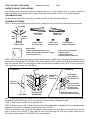
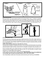
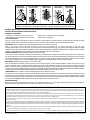
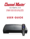
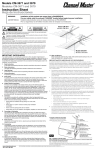
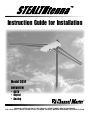
Instruction Guide for Installation
Model 3010
UHF/VHF/FM
• HDTV
• Digital
• Analog
WARNING: INSTALLATION OF THIS PRODUCT NEAR POWER LINES IS DANGEROUS.
FOR YOUR SAFETY, READ THE ENCLOSED “DANGER” BOOKLET BEFORE BEGINNING YOUR INSTALLATION.
TOOLS YOU WILL FIND HANDY
• Adjustable Wrench
• Pliers
WHERE TO MOUNT YOUR ANTENNA
Your antenna can be mounted on either the chimney, the roof, or on an outside wall or in an attic. Choose the
method that best suits your particular location. Mast tube size should be 1.25” to 1.66” outside diameter.
TRANSMISSION LINE
75 Ohm coaxial cable. RG-6 if running long distance. RG-6 or RG-59 for short distance.
ASSEMBLING ANTENNA
STEP 1: Remove the bottom cover from the unit. Unsnap the cover from the front end and clam shell open.
Front End
VHF element
LEFT side
LEFT
SIDE
VHF element
RIGHT side
RIGHT
SIDE
Main Unit
(bottom view)
4 - M6 x 12mm
self tap screws
2 - M4 x 10mm
self tap screws
Hardware Bag
2 - M4 x 10mm self tap screws (cover)
4 - M6 x 12mm self tap screws (VHF elements)
1 - mounting nest (mast)
4 - M6 external
tooth lockwashers
2 - M6 x 70mm hex head bolts
2 - M6 flat washers
1 - rubber weather boot
4 - M6 external tooth lockwashers
STEP 2: With the internal (cavity) part of the housing facing you, slide the left VHF element through the slots in
the left side of the housing. See FIGURE A. Be sure the element slides under the PCB. Slide the element all the
way in so that the slots in the elements are totally around the pre-installed screws. Note: The four screws are
only turned down half way. See FIGURE B.
FIGURE A
FIGURE B
PCB
+
Pre-installed
screw (halfway
turned down "4")
VHF element
to slide
under PCB
+
+
VHF slots
in housing
+
+
+
+
LEFT SIDE
+
INSIDE VIEW
Line up the holes
in the element with
the holes in the
mounting bosses
Slide element slot in all of
the way (2 slots per element)
STEP 3: After the elements are totally in place, tighten the two pre-installed screws. Tighten to the point where
the element and PCB feel tight. Do not over tighten. This may result in stripping threads.
STEP 4: Repeat steps 2 and 3 for the opposite side.
STEP 5: Remove the four M6 x 12mm screws and four M6 external tooth lockwashers from the hardware bag.
Install them into the four remaining mounting holes. See FIGURE C.
STEP 6: Reinstall the cover. Be sure the two tabs on the back end of the cover slips into the two slots in the rear
wall of housing. See FIGURE D. Clam shell the cover shut and snap the front end in place. Install the two
M4 x 10mm cover screws. See FIGURE D. Do not over tighten.
FIGURE C
Recess for
snap fit
FIGURE D
Cover
Channel Master
+
+
Inside Housing
Bosses for
M4 x 10mm
screws (2)
+
+
Cover tab
slots (2)
Four M6 x 12mm
screws and M6
external tooth
lockwashers from
hardware bag
Cover
Tabs (2)
Inside rear wall
MOUNTING ANTENNA
Mount the antenna on the mast using nest bracket and (2) bolts provided. Locate “F” connector on underside
of housing. Screw on the mating cable connector (do not overtighten or allow unsupported cable to dangle from
antenna connector). Slide weather boot over connector and up tight against plastic bottom cover. Next, run the
cable through standouts mounted on the mast. This will prevent the weight of the cable from pulling on the
antenna. From this point, tape or cable tie could be used to tie the cable to the mast. Route cable to TV set.
"F" Connector
Mast
Nest/Bolts
Standout
Tape/Cable Tie
Ground Block
Ground Rod
LIGHTNING PROTECTION
The mast and antenna cable should be grounded for lightning protection. Run a #8 (or larger) aluminum or
copper ground wire from a bolt on the mast or base, down to a 4’-8’ ground rod driven at least 4 feet into the
earth. Run the ground wire as directly as possible to the ground rod and avoid making 90 degree or sharper
turns. A ground block (Channel Master ® Model 3274) should be connected to the antenna cable at the point
where it enters the house.
AIMING YOUR ANTENNA TOWARD THE TRANSMITTING STATION
Once the antenna installation is completed, turn your TV set on and have an assistant observe the reception.
If adjustments are necessary, loosen the nest bolts and turn the antenna until you get the best reception. Once
this is accomplished, tighten nest bolts securely but do not overtighten as damage to the housing may occur.
NOTE: If broadcast stations are in different directions, you may need an antenna rotator. This will allow you to
rotate the antenna and pinpoint stations from inside your home. (For more information on rotators, see the
complete line of Channel Master Antenna Rotators.)
If signal is weak, install optional power amplifier Channel Master Model 3038.
Find the installation you plan to make on the following page - READ THE INSTRUCTIONS FOR ASSEMBLING
THE ANTENNA AND THE INSTALLATION BEFORE YOU START THE ACTUAL WORK!
Your Channel Master retailer has all the mounts and accessories you’ll need for your installation.
ATTIC MOUNT
INSTALLATION
A
GUYED ROOF MOUNT
INSTALLATION
B
C
C
G
D
B
CHIMNEY MOUNT
INSTALLATION
F
WALL MOUNT
INSTALLATION
TRIPOD MOUNT
INSTALLATION
B
C
D
B
C
B
D
M
I
L
A
D
C
O
J
K
H
E
E
N
A-Roof Mount B-Mast C-Transmission Wire D-Snap-On Standouts E-Screw-In Standouts F-Guy Wire G-Guy Ring & Clamp
H-Eyebolts I-Chimney Mount Straps J-Chimney Mount K-Ground Mount L-Wall Mount M-Tripod Mount N-Pitch Pads O-Lag Screws
WARNING: INSTALLATION OF THIS PRODUCT NEAR POWER LINES IS DANGEROUS. FOR YOUR SAFETY, READ THE ENCLOSED “DANGER”
BOOKLET BEFORE BEGINNING YOUR INSTALLATION.
IMPORTANT SAFEGUARDS
• Remember, when working on a roof, use two men
• Never walk on a composition roof in cold weather
• Wear sneakers or crepe soles and use a safety rope
• Always watch for power lines
ATTIC INSTALLATION:
Using a roof mount, attach a short piece of mast to a convenient roof rafter. Attach and aim the antenna in the same manner as outlined for outdoor
installations. NOTE: Antennas should not be installed in an attic if the roof or walls are metal or are lined with foil backed insulation.
ROOF MOUNT: Used on peaked or flat type roofs. Suggested Height Limit: 10 feet above roof top.
Using a roof mount, connect the mast with guy ring and guy wires attached to the mount. Use three or four guy wires,
equally spaced around the mast, and anchor the guy wires to the roof or eaves with eyebolts. The guy ring should be clamped approximately 1 foot below
the antenna. Use roofing compound around the base of the mount, screws and eyebolts to seal against moisture. After the installation has been completed, mount the extra WARNING LABEL supplied with the antenna hardware to the mast at EYE LEVEL!
CHIMNEY MOUNTING: Suggested Height Limitation: 10 feet above rooftop.
First, check your chimney thoroughly for stability to make sure that it is strong enough to support the antenna during severe winds. Do not use a chimney that as loose bricks or mortar. Install the upper bracket just below the top course of bricks and the lower bracket just below the top course of bricks
and the lower bracket at least 2¹⁄₂ feet below the top bracket. (For maximum strength, space the brackets as far apart as possible.) After the installation has been completed, mount the extra WARNING LABEL supplied with the antenna hardware to the mast at EYE LEVEL!
WALL MOUNT: Suggested Height Limitation: 10 feet above rooftop.
If the roof overhang is not excessive, the side of the house can be used for mounting. If a wall mounted installation is done from the ground up, use a
ground mount with a “spike” at the ground. Position the wall brackets over a stud if possible; one above the other and space a minimum of three feet
apart. For metal siding, mark mounting holes, then drill pilot holes through the siding for mounting screws. If you use a 2-piece mast, assemble the pieces
as shown, making sure that they are properly locked together. Split between masts should be between the two wall brackets. After the installation has been
completed, mount the extra WARNING LABEL supplied with the antenna hardware to the mast at EYE LEVEL!
TRIPOD MOUNT: Use on peaked or flat roofs. Suggested Height Limit: 10 feet above roof top.
The tripod mount can be mounted to any style roof by adjusting the bracket on the center leg. Insert the mast into the tripod mount and place the mount
with legs over the roof rafters. Make sure the mast is vertical. Remove the protective covering from one side of the three pitch pads and place under the
base of each tripod leg with the tacky side towards the roof. Secure the tripod mount to the roof using lag screws. After the installation has been completed, mount the extra WARNING LABEL supplied with the antenna hardware to the mast at EYE LEVEL!
ANTENNA REMOVAL:
Removal of your antenna should be exactly in reverse of the installation instructions. For your own safety, please follow the instructions for installing the
antenna starting with the last step first. This is the only way to safely remove your antenna.
NINETY (90) DAY LIMITED WARRANTY
This CHANNEL MASTER ® equipment is warranted to be free from defects in material and workmanship under normal use and service. CHANNEL MASTER shall repair or replace defective equipment, at no charge, or
at its option, refund the purchase price, if the equipment is returned to CHANNEL MASTER not more than ninety (90) days after shipment. Removal or reinstallation of equipment and its transportation shall not be at
the cost of CHANNEL MASTER except CHANNEL MASTER shall return repaired or replaced equipment freight prepaid.
This Warranty shall not apply to equipment which has been repaired or altered in any way so as to affect its stability or durability, or which has been subject to misuse, negligence or accident. This Warranty does not
cover equipment which has been impaired by severe weather conditions such as excessive wind, ice, storms, lightning, or other natural occurrences over which CHANNEL MASTER has no control, and this Warranty
shall not apply to equipment which has been operated or installed other than in accordance with the instructions furnished by CHANNEL MASTER.
Claimants under this Warranty shall present their claims along with the defective equipment to CHANNEL MASTER immediately upon failure. Non-compliance with any part of this claim procedure may invalidate this
warranty in whole or in part.
THIS WARRANTY IS EXPRESSLY IN LIEU OF ALL OTHER AGREEMENTS AND WARRANTIES. ANY IMPLIED WARRANTY OF MERCHANTABILITY OR FITNESS FOR A PARTICULAR PURPOSE IS LIMITED IN
DURATION TO THE DURATION OF THIS WARRANTY. CHANNEL MASTER DOES NOT AUTHORIZE ANY PERSON TO ASSUME FOR IT THE OBLIGATIONS CONTAINED IN THIS WARRANTY AND CHANNEL
MASTER NEITHER ASSUMES NOR AUTHORIZES ANY REPRESENTATIVE OR OTHER PERSON TO ASSUME FOR IT ANY OTHER LIABILITY IN CONNECTION WITH THE EQUIPMENT DELIVERED OR
PROVIDED.
IN NO EVENT SHALL CHANNEL MASTER BE LIABLE FOR ANY LOSS OF PROFITS, LOSS OF USE, INTERRUPTION OF BUSINESS, OR INDIRECT, SPECIAL OR CONSEQUENTIAL DAMAGES OF ANY KIND.
In no event shall CHANNEL MASTER be liable for damages in an amount greater than the purchase price of the equipment.
Some states do not allow limitations on how long an implied warranty lasts, or allow the exclusion or limitation of incidental or consequential damages, so the above limitations or exclusions may not apply to you.
www.channelmaster.com
©2003 Channel Master LLC (8000873) ECN 9006327 1/03 Rev. C
Printed in China