Transcript
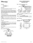
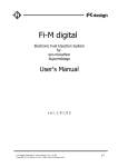
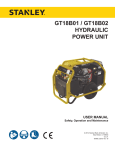
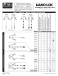
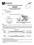
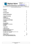
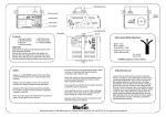
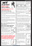
WHS208 TWO CHANNEL AUTOMOTIVE WIRELESS
HEADPHONE SYSTEM
Parts Supplied
z
z
z
Figure 1—Transmitter Mounting Diagram, continued
One IR Transmitter.
Two IR Transmitter Harness.
Two IR 2-Channel Headphones.
Important Notes
For best results, the IR transmitter must be installed as shown in figure 1
with the LEDs pointing towards the rear of the vehicle.
Audio input can be connected to either a low-level fixed audio output or a
variable level audio output (such as a speaker or headphone output). If it is
connected to a low-level output, only the volume control on the headphones
needs to be adjusted to control volume level. If connected to a variable level
outputs, then the volume adjustment needs to be accomplished at both the
sources and at the headphones.
Wire Harness (with RCA connectors)
Figure 2—Wiring Harnesses
1. Using two dual RCA (M/M) cables (not supplied—length to be determined
by installation requirements), connect one end of each to the Red and White
RCA jacks. Connect the other ends to the channel A and channel B to each
of the low level signal sources (A and B).
2. Connect pin 4 of the channel A harnness (Black wire, negative) to the
ground of the vehicle.
3. Connect pin 5 of the channel A harness (Red wire, +12 volt) to the ignition source. This is an ignition wire that provides +12V when the ignition key
is turned on.
Figure 3—IR Transmitter
IR Transmitter
1. Plug wire harness into transmitter.
2. Remove the 2 plastic caps on the transmitter to exposed the mounting
screw holes (figure 3).
3. Fasten transmitter to headliner using two short metal screws. Use caution, do not drill through the roof of the vehicle. Locate a roof metal beam
or glue a piece of wood to the metal roof.
4. Reinstall the plastic caps.
2-Channel Wireless Headphones
Follow the instuctions with the owner’s manual for the headphones for proper operation.
Figure 1—Transmitter Mounting Diagram
© 2005 Directed Electronics—all rights reserved
N88408 10-05