1
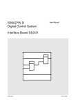
EtherLite
EIA-422 Mode (EtherLite 2 or 162 only)
Environmental Specifications
To operate a port of the EtherLite 162 EIA-422 in EIA-422 mode, set the
port’s EIA-422 ENABLED switch to the up position. Set the TERMINATION (422 ONLY) switch to the down position. This switch connects a
120 ohm, 1/2 watt resistor across the input signals.
EtherLite 2 EIA-422 ports are hard-wired to EIA-422 mode, and have no
termination installed. Pinouts are shown in the table below.
Operating Temperature
32°F (0°C) to 122°F (50°C) for units with less than 32 ports
32°F (0°C) to 95°F (35°C) for 32-port units
Note: 2-wire multidrop configuration for EIA-422 is not supported.
Operating or Storage Humidity
0 to 90% non-condensing
EIA-422 Pinouts
AC Power Requirements (maximum)
100-240 VAC, 50-60 Hz
15W (15VA) for units with less than 32 ports
25W (25VA) for 32-port units
Digi EtherLite serial port servers connect asynchronous serial ports to
10BASE-T and 100BASE-T Ethernet connections. Most EtherLite servers support speeds up to 115 Kbps or 230 Kpbs on all ports simultaneously.
Power Cord
Ethernet Cabling Requirements
The recommended power cord for North American units is:
UL Listed, CN, detachable type SJT or SVT, 3 conductor, 18 AWG, rated
125 V, 10 A.
The EtherLite unit requires an unshielded twisted-pair (UTP) 10Base-T
Ethernet or 100Base-TX connection. In order to maintain radio frequency
emissions compliance, use EIA/TIA 568-compliant Category 4 or Category 5 for 10Base-T and Category 5 only for 100Base-TX.
RJ-45
Direction
Pin
RTS*
1
RxD(-)
2
input(-)
DCD*
3
RxD(+)
4
input(+)
TxD(+)
5
output(+)
SG
6
TxD(-)
7
output(-)
CTS*
8
*EIA-232 signals on EtherLite EIA-422 only
Signal
Storage Temperature
-13°F (-25°C) to 167°F (75°C)
CAUTION: To prevent electric shock, do not remove the cover of an
EtherLite module. There are no user-serviceable parts inside. Refer servicing to qualified personnel.
Overview
Installing the EtherLite Software
Install the hardware before you install the device driver software. Follow
the software installation instructions on the Access Resource CD.
EIA-485 Mode (EtherLite 2 EIA-485 only)
EtherLite 2 EIA-485 ports are wired for half duplex multiple drop EIA485 mode and have no termination installed.
EIA-485 Pinouts
RJ-45
Direction
Pin
No connect*
1
No connect*
2
No connect*
3
TX(A)/RX(A)
4
Bidirectional
TX(B)/RX(B)
5
Bidirectional
GND
6
No connect*
7
No connect*
8
*Do not connect any signal.
Hardware
Information Guide
Signal
Copyright
The Digi logo and EtherLite are registered trademarks of Digi International. All other brand and product
names are trademarks of their respective holders.
© Digi International Inc., 2000
All Rights Reserved
Information in this document is subject to change without notice and does not represent a commitment on
the part of Digi International.
Digi provides this document “as is”, without warranty of any kind, either expressed or implied, including, but not limited to, the implied warranties of fitness or merchantability for a particular purpose. Digi
may make improvements and/or changes in this manual or in the product(s) and/or the program(s)
described in this manual at any time.
This product could include technical inaccuracies or typographical errors. Changes are periodically made
to the information herein; these changes may be incorporated in new editions of the publication.
90033900D
Installing the EtherLite Hardware
Rack Mount Considerations
1.
Write the MAC address of the EtherLite module on the following
line. It will be needed during software installation. This address is
printed on a label next to the power plug at the back of the unit.
MAC Address # 00AOE7______________
When doing a rack mount installation consider the following:
• Cumulative power requirements of the unit and other equipment
installed in the rack. Do not overload rack supply circuits.
Connect the Ethernet cable to the unit using the RJ-45 jack labeled
10BASE-T or 10/100BASE-T located on the front of the cabinet.
Use the provided straight-through cable to connect the unit to a hub.
Connecting directly to an Ethernet card will require a 10Base-T
crossover cable (not provided). Note that either wiring scheme
requires that the twisted pairs be used for specific pairs of pins: 1&2,
3&6, 4&5, and 7&8.
•
Safety and stability. Always stack the rack from bottom up to ensure
a stable and safe rack.
Note: The EtherLite 32 weighs 5.8 lbs (2.6 kgs).
•
Air flow in the rack. Make sure the unit’s ambient temperature does
not exceed 95°F (35°C).
•
Grounding. Earth ground the unit reliably to the rack system. The
earth ground connection must be maintained when the supply connection is other than a direct connection to the branch circuit.
2.
RJ-45 Pinouts
Straight-through
Pin
to
Pin
1
2
3
4
5
6
7
8
3.
to
to
to
to
to
to
to
to
1
2
3
4
5
6
7
8
Crossover
Pin
to
Pin
1
2
3
4
5
6
7
8
to
to
to
to
to
to
to
to
3
6
1
4
5
2
7
8
Pin 1
Pin x
EIA - 232 Connectors
Many EIA-232 serial devices implement their serial ports with DB-25
connectors. The EtherLite units have serial ports implemented with 8-pin
RJ-45 modular jacks, with each signal using EIA-232 voltage levels. The
figures below shows the pinouts of all these connector types.
1
13
RJ-45 Plug
For the EtherLite 32, a rack mount kit is included. The rack mount brackets may be installed at either the front or rear of the unit.
CAUTION: To prevent electric shock, do not remove the module
cover. There are no user-serviceable parts inside. Refer
servicing to qualified personnel only.
2.
Align the countersunk holes of the bracket with the vacated holes in
the cabinet. Use the countersink screws to fasten the bracket to the
cabinet.
Pin x
Male DB-25
EtherLite
RJ-45 Pin
1
2
3
4
5
6
7
8
Signal
DB-25 Pin
DB-9 Pin
RTS (out)
DSR (in)
DCD (in)
RxD (in)
TxD (out)
GND
DTR (out)
CTS (in)
4
6
8
3
2
7
20
5
7
6
1
2
3
5
4
8
IMPORTANT: RJ-45 cables designed for other Digi products must not
be used with Digi EtherLite and SCSI Terminal Server products. The
EtherLite RJ-45 pin configuration differs from the configuration of the
RJ-45 connectors used on other Digi products. The table above shows the
different signals, along with the standard DB-25, DB-9 and the EtherLite
8-pin RJ-45 pinout.
The most convenient method of mating DB-25 and DB-9 serial devices
to your EtherLite Port Server is to use RJ-45 to DB-25 and RJ-45 to DB9 adapters. This allows the DTE/DCE selection to occur at the adapter,
while using “straight-through” modular cables. To assure CE
(Conformité Européenne) mark compliance (Europe), all serial cables
must be shielded. The following RJ-45 to DB-25 adapters are available
from Digi International, along with two-meter unshielded straightthrough modular cables:
RJ-45 to DB-25 Adapters
13
1
RJ-45 Plug
14
25
To install each bracket, do the following:
Remove the two screws on the side of the cabinet.
Pin 1
25
14
Assign an IP address to the EtherLite module.
You will need to go to the software installation procedures on the
Access Resource CD for information on how to assign an IP address.
Rack Mount Installation
1.
EIA-232 DTE Pinouts
Female DB-25
P/N 76000450
(DTE to Modems)
RJ-45
DB-25
Signal
Male
Jack
1
RTS
4
2
DSR
6
3
DCD
8
4
RxD
3
5
TxD
2
6
GND
7
7
DTR
20
8
CTS
5
P/N 76000451
(DCE to Terminals/Printers)
RJ-45
DB-25
Signal
Jack
Male
1
RTS
5
2
n/c
6
3
DCD
20
4
RxD
2
5
TxD
3
6
GND
7
7
DTR
8
8
CTS
4