1
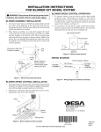
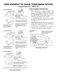
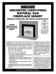
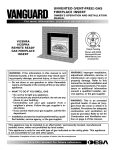
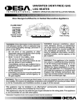
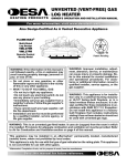
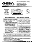
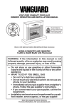
MODELS: VCBK4R &VCBK4L FAN KIT
INSTALLATION AND OPERATING INSTRUCTIONS
INSTALLING BLOWER BEFORE MOUNTING FIREPLACE
Note: Fireplace must be properly connected to a 110V power source
before blower can be operated.
1. Remove large knockout tab (see Figure 1).
2. Align two holes on side of rectangular bracket with two holes
on side frame. Secure with screws provided (see Figure 7).
3. Place blower assembly in fireplace and plug male electrical
connector into female connector already in fireplace. Make sure
rocker switch wire protrudes through notch in fireplace side (see
Figure 2). Connect wires with rocker switch.
4. Take four sheet metal screws provided and secure blower assembly to fireplace through holes (see Figure 3). Blower should
now be in place and look similar to Figure 4.
Note See instructions on reverse side if FULL VIEW glass doors
are installed.
Fireplace
Blower
Assembly
Knockout Tab
Electrical Connection
Rocker Switch
and Wiring
Figure 1
Male Electrical
Connector
Figure 2
Blower
Assembly
Fireplace
Sheet Metal
Screws
Rectangular
Bracket
ON/OFF Switch
Fireplace Face
Figure 3
Figure 4
INSTALLING BLOWER AFTER MOUNTING THE
FIREPLACE
Note: Fireplace must be properly connected to a 110V power source
before blowers can be operated.
1. Remove three screws that secure side brick retainers. Pull out
side brick exposing blower cover plate on right side of fireplace
(see Figure 5).
2. Remove blower cover plate (see Figure 6).
3. Place blower assembly through hole in firebox. Make sure wire
protrudes through notch in fireplace side. Align two holes on
side of rectangular bracket with two holes on side frame. Secure
with screws provided (see Figure 7). Blower assembly should
now look similar to Figure 8.
4. Before replacing blower cover plate, plug male electrical connector on blower assembly into female socket already in fireplace.
Replace blower cover plate, side brick and retainer before using
fireplace.
Fan
Cover
Plate
Knockout
Plate
Side Brick
Side Brick
Retainer
Figure 5
Figure 6
Fireplace
Side
Firebox
Rectangular
Bracket
Fan Assembly
Rectangular
Bracket
ON/OFF
Switch Wiring
ON/OFF Switch
Fireplace Face
Figure 7
Figure 8
SPECIAL INSTRUCTIONS FOR GLASS DOORS
If doors are installed, it is necessary to remove the right door and side frame. To remove door, press upper hinge spring in door track and
slide track and slide door assembly to the left. To remove side door frame, remove top and lower most hex head screws securing frame.
56105
NOT A UPC
2701 Industrial Drive
P.O. Box 90004
Bowling Green, KY 42102-9004
For more information, visit www.desatech.com
56105
Rev. C
01/06