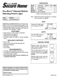
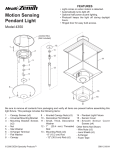
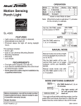
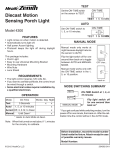
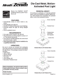
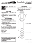
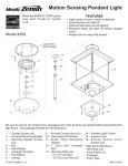
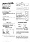
1
OPERATION
Motion Sensing
Porch Light
Mode:
On-Time
Test
5 Sec
Auto
1, 5, or 10 min
Manual
Until Dawn*
Works: Day Night
x
x
x
x
* resets to Auto Mode at dawn.
Note: When first turned on wait about 1 1/2 minutes
for the circuitry to calibrate.
TEST
ON-TIME
Set the ON-TIME switch
on the sensor to TEST.
TEST 1 5 10 MIN
AUTO
PF-4305
FEATURES
Set ON-TIME switch to
1, 5, or 10 minutes.
• Light comes on when motion is detected.
• Automatically turns light off.
• Photocell keeps the light off during daylight
hours.
This package includes:
• Porch Light
• Easy to use Universal Mounting Bracket
• Mounting Hardware
• Wire Nuts
• Lens Shield
REQUIREMENTS
• The Light Control requires 120 volts AC.
• If you want to use Manual Mode, the control must
be wired through a switch.
• Some electrical codes require installation by
a qualified electrician.
ON-TIME
TEST 1 5 10 MIN
MANUAL MODE
Manual mode only works at
night because daylight returns
the sensor to AUTO.
Flip the light switch off for one
second then back on to toggle
between AUTO and MANUAL
MODE.
1 Second OFF
then...
Manual mode works only with
the ON-TIME switch in the 1, 5,
or 10 position.
... back on.
MODE SWITCHING SUMMARY
TEST
AUTO
Before installation, record the model number
listed inside the fixture. Attach receipt in case
of possible warranty issues.
Model Number:
© 2006 DESA Specialty Products™
MANUAL MODE
ON-TIME Switch at 1, 5, or
10 minutes
Flip light switch off
for one second then
back on*
* If you get confused while switching modes, turn the
power off for one minute, then back on. After the calibration time the control will be in the AUTO mode.
598-1168-03
DISASSEMBLE LIGHT FIXTURE
INSTALL UNIVERSAL MOUNTING
BRACKET
1. Remove two decorative nuts from light fixture
cover.
2. Remove cover from base.
For best performance, mount the fixture at least 8
feet (2.4 m) above the ground.
WARNING: Turn power off at circuit
breaker.
1. Tighten the two fixture screws finger tight.
2. Attach universal mounting bracket to junction
box securely with the two screws provided.
Light Fixture Base
Y
IVIT
SIT
SEN
LO
-M
- HI
10
5 E
1
T -TIM
TESON
MIN
Junction Box
Light Fixture Cover
Universal Mounting
Bracket
Decorative Nut
Junction Box Screw
3. Remove two decorative nuts from fixture screws
in universal mounting bracket.
4. Remove universal mounting bracket from
base.
Fixture Screw (Tightened
Finger Tight)
WIRING LIGHT FIXTURE
1. Connect the junction box wires and the fixture
wires together as shown in the following diagrams.
Universal
Mounting
Bracket
CAUTION: DO NOT remove wire connector from RED wire or connect the RED wire
unless you want to control other lights from
this motion sensor fixture.
Decorative Nut
2. Twist and secure wires with wire nuts.
SE
ITIV
NS
LO
-M
ITY
- HI
10
5
1 IME
ST -T
TE ON
MIN
Note: If you have a metal junction box use the recommended grounding method shown in the following
illustration. If you are uncertain about the grounding
method, consult your local building code.
2
598-1168-03
Other Wiring Options
Bare Ground Wire
Ground Screw
This fixture can be wired to control another standard
or motion sensing light fixture(s). See the following
wiring diagrams for proper connections.
Note: All wiring should be run in accordance with
the National Electrical Code through conduit or
another acceptable means. Contact a qualified
electrician if there is any question as to the
suitability of the system.
When controlling an additional light fixture(s), the
maximum wattage of the motion sensor on this
fixture should be observed. See illustration below
for an example of a maximum lamp wattage load
calculation.
Metal Junction
Box
Pigtail (not
supplied)
White to White
Fixture Bare
Ground Wire
Black to Black
Recommended Grounding Method
Black to Black
Maximum Lamp
Wattage Rating
for Light Fixture –
100 Watts
White to White
Maximum Load for
Motion Sensor –
500 Watts
Ground to Ground
CONTROLLING Fixture
Maximum Lamp
Wattage Rating
for Light Fixture –
100 Watts
CONTROLLED Fixture 1
Maximum Lamp
Wattage Rating
for Light Fixture –
100 Watts
CONTROLLED Fixture 2
One Motion Sensing Light
Black to Black
TOTAL Load for
Motion Sensor –
300 Watts (200 Watts Remaining)
White to White
Ground to
Ground
IMPORTANT: When determining the maximum
lamp wattage rating of the fixture to be controlled,
refer to the maximum lamp wattage label on the
fixture and not the wattage rating on the lamp(s)
currently installed in the fixture.
Two Motion Sensing Lights (Working Independently)
White to White
Black to Black
Red to Black
Ground to
Ground
Motion Sensing
Light
Standard Light
Fixture
Wiring Motion Sensing Light to Control Standard
Fixture
598-1168-03
3
Black to
Black
White to White
TESTING
Black to Red
and Black
1. Turn on the circuit breaker and light switch.
Red to Black
Note: Sensor has a 1 1/2 minute warm up period
before it will detect motion. When first turned on
wait 1 1/2 minutes.
Ground to
Ground
2. Set the SENSITIVITY switch to the “M” position
and the ON-TIME switch to the TEST position.
Motion Sensing
Light
Controlled Motion
Sensing Light
SENSITIVITY
Wiring Motion Sensing Light to Control Another
Motion Sensing Light
It is also possible to wire two motion sensing lights
so that either unit will turn on both lights at the same
time (dual controlled system). It is recommended that
only people with electrical wiring experience attempt
this configuration. Please call our customer service
number (1-800-858-8501) before attempting this
wiring. If the dual controlled wiring is not done
correctly, it can destroy both motion sensing
fixtures and void your warranty.
SE
ITY
ITIV
NS
LO
-M
LO - M - HI
- HI
10
5
1 IME
ST -T
TE ON
MI
N
Sensor
Lens
TEST 1 5 10 MIN
ON-TIME
3. Walk through the coverage area noting where
you are when the lights turn on. In TEST mode,
light will stay on for only 5 seconds then turn
off.
4. Adjust the SENSITIVITY to increase or decrease
the range as needed. Too much sensitivity may
cause false triggering due to heat sources in the
coverage area (see Adjustment of Coverage
Area or Troubleshooting section).
5. Set the amount of TIME you want the light to
stay on after motion is detected (1, 5, or 10
minutes).
INSTALL FIXTURE BASE TO
JUNCTION BOX
1. Push wires into the junction box.
2. Slide light fixture base onto fixture screws and
tighten decorative nuts snugly against the base.
3. Install four candelabra base light bulbs (25
Watts maximum each).
4. Refer to TESTING section before installing
cover.
5. After switches are set and testing is complete,
use the 2 decorative nuts to install the cover.
360°
Junction Box
8 ft. (2.4 m)
Fixture Screw
25 Watt Candelabra
Base Bulb
Decorative Nut
30 Feet (9.1 m)
in all Directions
Maximum Range
Angle*
Coverage
(Top View)
* Without lens shield installed.
VITY
SE
ITI
NS
LO
-M
- HI
10
5
1 IME
ST -T
TE ON
MI
N
4
598-1168-03
The sensor is less sensitive to motion directly
towards it and more sensitive to motion across
coverage area.
1. Break off the amount of lens shield needed to
block the desired area of coverage.
2. Cut desired amount of foam tape needed to
adhere the lens shield to the sensor lens.
3. Remove paper backing from one side of cut
foam tape and adhere foam tape to inside of
lens shield.
4. Remove paper backing from other side of cut foam
tape and adhere lens shield to sensor lens.
Motion
Motion
Sensor
Least Sensitive
SE
Most Sensitive
ITY
ITIV
NS
LO
-M
-H
I
M
10
5
1 IME
ST -T
TE ON
IN
Adjustment of Coverage Area
The sensor on this light fixture detects “motion”
by the movement of heat (body heat) across the
coverage area. However, following are examples
of objects that also produce heat and can cause
the sensor to false trigger:
• Pools of Water
• Air Conditioners
• Dryer Vents
• Fenced-In Animals
• Heating Vents
• Automobile Traffic
If you suspect that a heat source of this type is falsely
triggering the sensor and reducing the sensitivity
does not solve the problem, then a lens shield
(included) can be installed. The plastic lens shield
is divided into 6 sections. Each section will reduce the
coverage angle by 30 degrees. Also, the tip of each
section may be removed to change the effective
range of the sensor.
Lens
Shield
Lens
Shield
Lens Shield
5. Retest to confirm that the sensor is no longer
false triggering.
Note: To help determine amount of lens shield
required, apply small sections one at a time. Additional sections can be applied if necessary.
SPECIFICATIONS
Range ........................... Up to 30 ft. (9.1 m)
[varies with surrounding
temperature].
Sensing Angle .............. 360°
Electrical Load .............. Up to 100 Watt Maximum Incandescent (Up
to 25 Watt Maximum
each lampholder).
Bulb Type ...................... Candelabra Base, Type
“B”, 25 Watt Maximum
Sensor Capacity ........... Up to 500 Watt (4.2 A.)
Maximum
Power Requirements .... 120 VAC, 60 Hz
Operating Modes .......... TEST, AUTO, and
MANUAL MODE
ON-Timer ...................... 1, 5, 10 minutes
Area
Blocked
Effective
Coverage Area
(Top View)
Area
Blocked
DESA Specialty Products™ reserves the right to
discontinue products and to change specifications at
any time without incurring any obligation to incorporate new features in products previously sold.
Portion
Removed
598-1168-03
Sensor
Lens
5
TROUBLESHOOTING GUIDE
SYMPTOM
SYMPTOM
POSSIBLE CAUSE
POSSIBLE CAUSE
Light will not 1. Light switch is turned off.
come on.
2. Bulbs are loose or burned out.
3. Fuse is blown or circuit breaker
is turned off.
4. Daylight turn-off is in effect (recheck after dark).
5. Incorrect circuit wiring, if this is
a new installation.
Light stays on 1. There is a heat source like an
continuously.
air vent, dryer vent, or brightlypainted, heat-reflective surface in
the coverage area. (Install shield
on sensor in the direction of heat
source.)
2. Sensitivity is set too high. (Reduce
sensitivity.)
Light comes on 1. Sensor may be installed in a
in daylight.
relatively dark location.
2. Sensor is in Test. (Set control
switch to an ON-TIME position.)
Light flashes on 1. Sensor is in the Test mode. (While
and off.
in TEST mode, light only stays on
for 5 seconds.)
Light does not 1. Nearby large, light-colored objects
stay on in Manreflecting light may trigger the
ual mode.
shut-off feature. Do not point other
lights at the sensor.
Light comes on 1. Sensor may be sensing small
for no apparent
animals or automobile traffic.
reason.
(Reduce sensitivity.)
TECHNICAL SERVICE
Please call 1-800-858-8501 for assistance before returning product to store.
If you experience a problem, follow this guide. You may also want to visit our Web site at: www.desatech.
com. If the problem persists, call* for assistance at 1-800-858-8501, 7:30 AM to 4:30 PM CST (M-F).
You may also write* to:
DESA Specialty Products™
P.O. Box 90004, Bowling Green, KY 42102-9004
ATTN: Technical Service Specialty Products
* If contacting Technical Service, please have the following information available: Model Number, Date of
Purchase, and Place of Purchase.
No Service Parts Available for this Product
THREE YEAR LIMITED WARRANTY
This is a “Limited Warranty” which gives you specific legal rights. You may also have other rights which vary from state to state or
province to province.
For a period of three years from the date of purchase, any malfunction caused by factory defective parts or workmanship will be
corrected at no charge to you.
Not Covered - Repair service, adjustment and calibration due to misuse, abuse or negligence, light bulbs, batteries, and other expendable items are not covered by this warranty. Unauthorized service or modification of the product or of any furnished component
will void this warranty in its entirety. This warranty does not include reimbursement for inconvenience, installation, setup time, loss of
use, unauthorized service, or return shipping charges.
This warranty covers only DESA Specialty Products™ assembled products and is not extended to other equipment and components
that a customer uses in conjunction with our products.
THIS WARRANTY IS EXPRESSLY IN LIEU OF ALL OTHER WARRANTIES, EXPRESS OR IMPLIED, INCLUDING ANY WARRANTY,
REPRESENTATION OR CONDITION OF MERCHANT ABILITY OR THAT THE PRODUCTS ARE FIT FOR ANY PARTICULAR PURPOSE OR USE, AND SPECIFICALLY IN LIEU OF ALL SPECIAL, INDIRECT, INCIDENTAL, OR CONSEQUENTIAL DAMAGES.
REPAIR OR REPLACEMENT SHALL BE THE SOLE REMEDY OF THE CUSTOMER AND THERE SHALL BE NO LIABILITY ON
THE PART OF DESA SPECIALTY PRODUCTS™ FOR ANY SPECIAL, INDIRECT, INCIDENTAL, OR CONSEQUENTIAL DAMAGES,
INCLUDING BUT NOT LIMITED TO ANY LOSS OF BUSINESS OR PROFITS, WHETHER OR NOT FORESEEABLE. Some states
or provinces do not allow the exclusion or limitation of incidental or consequential damages, so the above limitation or exclusion may
not apply to you. Proof of purchase is required for warranty claims.
6
598-1168-03
Nota: Cuando lo prenda por primera vez espere 1
1
/2 minutos para que el circuito se claibre.
PRUEBA
Ponga el interruptor de
ON-TIME
ON-TIME (DURACIÓN)
del detector en TEST
(PRUEBA).
TEST 1 5 10 MIN
Lámpara de portal con
detector de movimiento
AUTOMATICO
Ponga el interruptor de
tiempo (ON-TIME) en
la posición de 1, 5 ó 10
minutos.
TEST 1 5 10 MIN
MODO MANUAL
PF-4305
El modo manual funciona sólo
por la noche porque la luz del
día pone al detector en modo
AUTOMATICO.
Apague el interruptor por un
segundo y vuélvalo a prender.
El modo manual funciona sólo
cuando el interruptor de tiempo
(ON-TIME) está en la posición
de 1, 5 ó 10 minutos.
CARACTERÍSTICAS
• La luz se prende cuando se detecta movimiento.
• Apaga la luz automáticamente.
• La fotocélula mantiene la luz apagada durante
las horas del día.
Este paquete contiene:
• Lámpara del pórtico
• Soporte universal de fácil uso
• Ferretería de montaje
• Conectores de alambre
• Cubierta de la placa traslúcida
REQUISITOS
RESUMEN DE LAS MODALIDADES
DEL INTERRUPTOR
PRUEBA
FUNCIONAMIENTO
A tiempo:
Prueba
5 seg.
Autom.
1, 5 ó 10 min.
1 segundo
APAGADO
luego...
...préndalo.
• El Control de Luz requiere 120 VCA.
• Para usar el Sobrecontrol Manual, conecte el
control con un interruptor.
• Algunos códigos requieren instalación por
un electricista calificado.
Modalidad:
ON-TIME
Trabaja: Día Noche
x
AUTOM.
x
x
MODO
MANUAL
Manual
Hasta el
x
amanecer*
*Se pone en Automático al amanecer.
Mueva el interruptor de
tiempo (ON-TIME) a 1, 5 ó
10 minutos
Apague el interruptor por
un segundo y préndalo
de nuevo*
* Si se confunde mientras cambia de fases, apague la electricidad por un minuto y préndala de
nuevo. Después del tiempo de calibración el
control estará en fase AUTO(MATICA).
Antes de instalar, registre el número del modelo
mostrado dentro del aparato. Fije el recibo en
caso posibles reclamos por la garantía.
Número del modelo:
598-1168-03
© 2006 DESA Specialty Products™
7
598-1168-03 S
DESARME EL APARATO DE LUZ
INSTALE EL SOPORTE UNIVERSAL
DE MONTAJE
1. Retire las dos tuercas decorativas de la tapa
del aparato de luz.
2. Retire la tapa de la base.
Para un mejor desempeño, monte el aparato al
menos a 2,4m del suelo.
ADVERTENCIA: Desconecte la energía en
el disyuntor.
1. Apriete a mano los dos tornillos del aparato.
2. Sujete bien el soporte universal de montaje a
la caja de empalme usando los dos tornillos
provistos.
Base del aparato
de luz
Y
IVIT
SIT
SEN
LO
-M
- HI
10
5 E
1
T -TIM
TESON
MIN
Tapa del aparato
de luz
Caja de empalme
Tuerca
decorativa
Soporte universal
de montaje
Tornillo de la caja
de empalme
3. En el soporte universal de montaje retire de los
tornillos del aparato las dos tuercas decorativas.
4. Retire de la base el soporte universal de montaje.
Tornillo del aparato
(apretado a mano)
CABLEADO DEL APARATO DE LUZ
1. Conecte los conductores de la caja de empalme
apretándolos juntos con los conductores del
aparato como se muestra en los esquemas
que siguen.
Soporte
universal de
montaje
Tuerca decorativa
CUIDADO: NO retire el conector de alambre del conductor rojo ni conecte el conductor
ROJO a no ser que desee controlar otras luces
desde este aparato detector de movimiento.
SE
ITIV
NS
LO
-M
2. Tuerza y asegure los conductores con conectores de alambre.
ITY
- HI
10
5
1 IME
ST -T
TE ON
MIN
Nota: Si tiene una caja de empalme metálica use
el método de conexión a tierra recomendado que
se indica en la siguiente ilustración. Si tiene dudas
del método de conexión a tierra, consulte el código
local de construcción.
8
598-1168-03
Cuando controle aparato(s) de luz adicionales,
debe observarse la potencia máxima del detector
de movimiento de este aparato.Vea en la ilustración
de abajo un ejemplo para el cálculo de la potencia
máxima de la lámpara.
Conductor desnudo de conexión a tierra
Tornillo de conexión a tierra
Conductor flexible
(no provisto)
Caja metálica
de empalme
Conductor
desnudo del
aparato para
conexión a
tierra
Potencia nominal
máxima de la
lámpara para el
aparato de luz –
100 vatios
Blanco con
Blanco
Carga máxima para el
detector de movimiento –
500 vatios
Negro con
Negro
Método recomendado de conexión a tierra
Aparato
DE CONTROL
Aparato
CONTROLADO 1
Negro con Negro
Aparato
CONTROLADO 2
Blanco con Blanco
Potencia nominal
máxima de la
lámpara para el
aparato de luz –
100 vatios
Potencia nominal
máxima de la
lámpara para el
aparato de luz –
100 vatios
Carga TOTAL del
detector de movimiento –
300 vatios (200 vatios no usado)
Conductor tierra con
Conductor tierra
IMPORTANTE: Cuando determine la potencia
nominal máxima de la lámpara del aparato a ser
controlado vea la potencia máxima en la etiqueta
del aparato y no la potencia nominal en las lámparas
que están actualmente instaladas en el aparato.
Blanco con
Blanco
Una lámpara detectora de movimiento
Negro con Negro
Rojo con Negro
Conductor tierra con
Conductor tierra
Conductor
tierra con
Conductor
tierra
Negro con Negro
Blanco con Blanco
Aparato de luz detector
de movimiento
Aparato estándar
de luz
Cableado del aparato de luz detector de movimiento
para controlar un aparato de luz estándar
Dos lámparas detectoras de movimiento (trabajando independientemente)
Blanco con
Blanco
Otras opciones de cableado
Este aparato puede cablearse para controlar
otro(s) aparato(s) de luz estándar o detectores de
movimiento. Vea en los siguientes esquemas las
conexiones apropiadas.
Nota: Todo el cableado debe ser hecho de acuerdo
al Código Eléctrico Nacional por medio de conductos para cables u otras formas aceptables. Póngase
en contacto con un electricista calificado si
existe duda sobre la aptitud del sistema.
598-1168-03
Negro con
Negro
Rojo con
Negro
Negro
con el
Rojo y el
Negro
Conductor
tierra con
Conductor
tierra
Aparato de luz
detector de
movimiento
Luz detectora
de movimiento
controlada
Luz detectora de movimiento que controla otra luz
detectora de movimiento
9
PRUEBA
Es también posible cablear dos luces detectoras de
movimiento de modo que cualquiera de ellas encienda
ambas luces al mismo tiempo (sistema de control
doble). Se recomienda que sólo personas con amplios
conocimientos de electricidad conecten este tipo de
configuración. Por favor contacto con nuestro departamento de asistencia al cliente antes hacer este tipo
de conexión (vea Servicio Técnico). Si el cableado
del control doble no es hecho correctamente,
puede destruir ambos aparatos detectores de
movimiento e invalidad su garantía.
1. Prenda el cortacircuitos y el interruptor de
luz.
Nota: El detector tiene un período de cerca
de 1 1/2 minutos de calentamiento antes de
detectar movimiento. Cuando lo prenda por
primera vez, espere 1 1/2 minutos.
2. Calibre el interruptor SENSITIVITY (SENSIBILIDAD) poniéndolo en la posición “M” y el
interruptor “ON TIME” (“DURACIÓN”) en la
posición TEST (PRUEBA).
INSTALE LA BASE DEL APARATO A
LA CAJA DE EMPALME
SENSITIVITY
1. Empuje los conductores hacia la caja de
empalme.
2. Deslice la base del aparato por los tornillos del
aparato y apriete bien las tuercas decorativas
contra la base.
3. Instale cuatro bombillas con base tipo candelabro (de máximo 25 vatios cada una).
4. Antes de instalar la tapa vea la sección
PRUEBA.
5. Luego de calibrar los interruptores y completar
la prueba, use las 2 tuercas decorativas para
instalar la tapa.
SE
-M
- HI
MI
N
LO - M - HI
Placa traslúcida
del detector
TEST 1 5 10 MIN
ON-TIME
3. Camine por el área de protección dándose
cuenta dónde está cuando la luz se prende.
En la fase PRUEBA, la luz se encenderá sólo
5 segundos y luego se apagará.
4. Regule la SENSIBILIDAD para aumentar o disminuir el margen según sea necesario. Demasiada
sensibilidad puede ocasionar activaciones falsas
debido a fuentes de calor en las áreas de cobertura (Vea Regulación del área de cobertura o la
sección Guia de investigacion de averias).
5. Fije el período de tiempo (ON-TIME) que la luz
debe quedarse prendida después de detectar
movimiento (1, 5 ó 10 minutos).
Caja de empalme
Tornillo del
aparato
Bombilla de 25
vatios con base
tipo candelabro
Tuerca decorativa
ITY
ITIV
NS
LO
10
5
1 IME
ST -T
TE ON
360°
2.4 m
VITY
SE
ITI
NS
LO
-M
- HI
10
5
1 IME
ST -T
TE ON
MI
N
9.1m en todas
las direcciones
Alcance Máximo
Angulo de
Cobertura Máxima*
(Vista desde arriba)
* Sin la cubierta de la placa traslúcida instalada.
10
598-1168-03
2. Corte la canti- Cubierta de la placa traslúcida
dad necesaria
de cinta espumosa que
necesita para
adherir la cubierta a la placa
traslúcida.
Placa traslúcida del detector
3. Retire el papel
protector de un
lado de la cinta espumosa y adhiérala al interior
de la cubierta.
4. Retire el papel protector del otro lado de la
cinta espumosa cortada y adhiera la cubierta
a la placa traslúcida del detector.
5. Vuelva a probar para confirmar que el detector
ya no presenta activaciones erróneas.
Nota: Para ayudar a determinar la cantidad de
cubierta requerida en la placa traslúcida, ponga las
secciones pequeñas una por vez. Si es necesario
puede añadir secciones.
El detector es menos sensible a movimientos
hacia el detector y más sensible a movimientos
transversales en el área de cobertura.
ITY
SE
ITIV
NS
LO
Movimiento
Detector
Lo menos sensible
Lo más sensible
REGULACIÓN DEL ÁREA DE
COBERTURA
El detector de este aparato de luz detecta “movimiento” gracias al movimiento del calor (calor corporal) a través del área de cobertura. Sin embargo,
lo que sigue son ejemplos de objetos que pueden
también producir calor y hacer que el detector se
active erróneamente.
• Charcos de agua • Acondicionadores de aire
• Respiraderos de secadoras
• Respiraderos de la calefacción
• Animales tras las vallas • Tráfico automotor
Si usted sospecha que una fuente de calor de este tipo
está activando erróneamente el detector y que reduciendo la sensibilidad no soluciona el problema, entonces
puede instalarse la cubierta de la placa traslúcida
(incluida). La cubierta plástica de la placa traslúcida
está dividida en 6 secciones. Cada sección reducirá
el área de cobertura en 30 grados. Además, puede
retirarse la punta de cada sección para cambiar el
alcance efectivo de cada detector.
Cubierta de la
placa traslúcida
Área efectiva de
cobertura (Vista
desde arriba)
MIN
ESPECIFICACIONES
Alcance ............................. Hasta 9.1 m (varía con la
temperatura del medio
ambiente).
Angulo de detección ......... 360°
Carga Eléctrica ................. H a s t a 1 0 0 V a t i o s
máximo de luz incandescente (hasta
25V máximo por cada
portalámparas).
Tipo de bombilla ............... Base candelabro, tipo “B”
de 25 vatios máximo
Capacidad del Detector .... Hasta 500 Vatios (4.2
A) máximo
Requisitos de Energía ...... 120 VCA, 60 Hz
Fases de Operación ......... FASES DE PRUEBA,
AUTOMÁTICO Y MANUAL
Temporizador de
duración (del encendido) ...........1, 5, 10 minutos
Área
bloqueada
Área
bloqueada
DESA Specialty Products™ se reserva el derecho de descontinuar productos y de cambiar
especificaciones a cualquier momento sin incurrir
en ninguna obligación de tener que incorporar
nuevas características en los productos vendidos
con anterioridad.
Parte retirada
1. Rompa la cantidad necesaria de cubierta que
necesita para bloquear una área deseada de
la cobertura.
598-1168-03
- HI
10
5
1 ME
ST TI
TE ON-
Movimiento
Cubierta
de la placa
traslúcida
-M
11
GUIA DE INVESTIGACION DE AVERIAS
SINTOMA
SINTOMA
POSIBLE CAUSA
La luz no se 1. El interruptor de luz está apagado.
enciende.
2. Las bombillas están flojas o quemadas.
3. El fusible está quemado o el cortacircuitos está apagado.
4. La desconexión de luz del día
está en efecto. (Compruébelo al
anochecer).
5. Alambrado incorrecto, si ésta es
una nueva instalación.
POSIBLE CAUSA
La luz se queda 1. Hay una fuente de calor como ventoprendida contisas de aire, respiradero de secadora,
nua-mente.
o hay en el área de cobertura una
superficie brillante que refleja calor.
(Instale la cubierta en el detector en
la dirección de la fuente de calor).
2. La Sensibilidad es demasiado alta.
(Apague el Aumento de Distancia).
La luz se prende 1. El detector está en la fase Prueba.
y se apaga.
(Mientras está en la fase PRUEBA,
la luz sólo queda encendida por 5
segundos).
La luz se prende 1. El detector debe ser instalado en
durante el día.
un lugar relativamente oscuro.
2. El detector esta en la posición prueba. (Fije el interruptor del control a
la posición de TIEMPO).
La luz no queda 1. Objetos cercanos, grandes y de
encendida en el
colores brillantes que reflejan luz
modo manual.
pueden activar la característica de
apagado. No apunte otras luces
hacia el detector.
La luz se prende 1. El detector puede estar detectando
sin ninguna raanimales pequeños o tráfico autozón aparente.
motor. (Reduzca la sensibilidad).
SERVICIO TÉCNICO
(No enviar los productos)
Si tiene algún problema por favor siga esta guía. Lo sentimos, pero no podemos contestar preguntas en
español por teléfono. Usted puede también escribir* a:
DESA Specialty Products™
P.O. Box 90004
Bowling Green, KY 42102-9004
* Si se llama al Servicio Técnico, por favor tener lista la siguiente información: Número de Modelo, Fecha
de compra y Lugar de compra.
No hay piezas de servicio disponibles para este producto.
GARANTÍA LIMITADA A 3 AÑOS
Esta es una “Garantía Limitada” que le da a Ud. derechos legales específicos. Usted puede también tener otros derechos que varían
de estado a estado o de provincia a provincia.
Por un período de 3 años desde la fecha de compra, cualquier mal funcionamiento ocasionado por partes defectuosas de fábrica o
mano de obra será corregido sin cargo para Ud.
No cubierto - Servicio de reparación, ajuste y calibración debido al mal uso, abuso o negligencia, bombillas, baterías, u otras partes
fungibles no están cubiertas por esta garantía. Los Servicios no autorizados o modificaciones del producto o de cualquier componente
que se provee invalidarán esta garantía en su totalidad. Esta garantía no incluye reembolso por inconveniencia, instalación, tiempo
de instalación, perdida de uso, servicio no autorizado, o costos de transporte de retorno.
Esta garantía cubre solamente los productos ensamblados por DESA Specialty Products™ y no se extiende a otros equipos o
componentes que el consumidor usa junto con nuestros productos.
ESTA GARANTÍA ESTÁ EXPRESAMENTE EN LUGAR DE OTRAS GARANTÍAS, EXPRESADAS O SOBREENTENDIDAS, INCLUYENDO CUALQUIER GARANTÍA, REPRESENTACIÓN O CONDICIÓN DE COMERCIABILIDAD O QUE LOS PRODUCTOS
SE ADAPTEN PARA CUALQUIER PROPÓSITO O USO EN PARTICULAR, Y ESPECIFICAMENTE EN LUGAR DE TODOS LOS
DAÑOS ESPECIALES, INDIRECTOS, INCIDENTALES Y CONSECUENTES.
LA REPARACIÓN O EL REEMPLAZO DEBERÍA SER LA ÚNICA SOLUCIÓN DEL CLIENTE Y NO HABRÁ RESPONSABILIDAD POR
PARTE DE DESA SPECIALTY PRODUCTS™ POR CUALQUIER DAÑO ESPECIAL, INDIRECTO, INCIDENTAL O CONSECUENTE,
INCLUIDOS PERO NO LIMITADOS A CUALQUIER PÉRDIDA DE NEGOCIO O GANACIAS SEAN O NO PREVISIBLES. Algunos
estados o provincias no permiten la exclusión o limitación de daños incidentales o consecuentes, de modo que la limitación o exclusión
arriba indicada puede que no se aplique a Ud. Para reclamos por la garantía se requiere la prueba de compra.
12
598-1168-03