1
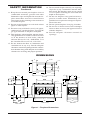
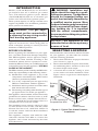
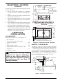
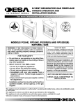
36" CORNER UNIT, B-VENT DECORATIVE GAS FIREPLACE
OWNER’S OPERATION AND INSTALLATION MANUAL
(V)GL36CR(E) Right Side
Corner, Natural Gas
(V)gl36crp(e) Right Side
Corner, Propane/LP
(V)gl36cl(e) Left Side
Corner, Natural Gas
(V)gl36clp(e) Left Side
Corner, Propane/LP Gas
WARNING: If the information in these instructions is
not followed exactly, a fire or explosion may result
causing property damage, personal injury or death.
FOR YOUR SAFETY
— Do not store or use gasoline or any other flammable
vapors or liquids in the vicinity of this or any other
appliance.
— WHAT TO DO IF YOU SMELL GAS :
• Do not try to light any appliance.
• Do not touch any electrical switch;
• Do not use any phone in your building.
• Immediately call your gas supplier from a neighbor’s
phone. Follow the gas supplier’s instructions.
• If you cannot reach your gas supplier, call the fire
department.
— Installation and service must be performed by a qualified installer, service agency or the gas supplier.
INSTALLER: Leave this manual with the appliance.
CONSUMER: Retain this manual for future reference.
For more information, visit www.desatech.com
TABLE OF CONTENTS
Safety Information................................................ 2
Dimensions........................................................... 4
Introduction........................................................... 5
Selecting Location................................................ 5
Fireplace Installation............................................ 6
Operating Fireplace.............................................11
Inspecting Burner............................................... 13
Cleaning and Maintenance................................. 14
Technical Service............................................... 14
Specifications..................................................... 15
Wiring Diagrams................................................. 15
Troubleshooting.................................................. 16
Replacement Parts and Accessories.................. 18
Limited Warranty..................................Back Cover
Safety Information
WARNING: Improper installation, adjustment, alteration, service or maintenance can cause injury or property damage. Refer to this manual for correct installation
and operational procedures. For assistance or additional information consult a qualified installer, service
agency or the gas supplier.
NOT FOR USE WITH SOLID FUEL
CHECK LOCAL CODES PRIOR TO INSTALLATION
SAVE THIS BOOK
This book is valuable. In addition to instructing you on
how to install and maintain your appliance, it also contains information that will enable you to obtain replacement parts or optional accessory items when needed.
Keep it with your other important papers.
This appliance may be installed in an aftermarket* permanently manufactured (mobile) home, where not prohibited by state or local codes. This appliance is only for
use with the type of gas indicated on rating plate. This
appliance is not convertible for use with other gases,
unless a certified kit is used and installed by a qualified
technician.
*Aftermarket: Completion of sale, not for purpose of resale, from the manufacturer.
www.desatech.com
112301-01D
Safety Information
Continued
WARNING: This product contains and/or generates chemicals
known to the State of California
to cause cancer or birth defects
or other reproductive harm.
IMPORTANT: Read this owner’s
manual carefully and completely
before trying to assemble, operate or service this fireplace.
Improper use of this fireplace
can cause serious injury or death
from burns, fire, explosions,
electrical shock and carbon
monoxide poisoning.
DANGER: Carbon monoxide
poisoning may lead to death!
This fireplace is a vented product. This fireplace
will not produce any gas leakage into your home if
properly installed. This fireplace must be properly
installed by a qualified service person. If this unit is
not properly installed by a qualified service person,
gas leakage can occur.
Carbon Monoxide Poisoning: Early signs of
carbon monoxide poisoning resemble the flu, with
headaches, dizziness or nausea. If you have these
signs, the fireplace may not have been installed
properly. Get fresh air at once! Have fireplace
inspected and serviced by a qualified service
person. Some people are more affected by carbon
monoxide than others. These include pregnant
women, people with heart or lung disease or
anemia, those under the influence of alcohol and
those at high altitudes.
Propane/LP gas and natural gas are both odorless.
An odor-making agent is added to each of these
gases. The odor helps you detect a gas leak. However, the odor added to these gases can fade. Gas
may be present even though no odor exists.
Make certain you read and understand all warnings.
Keep this manual for reference. It is your guide to
safe and proper operation of this fireplace.
WARNING: Any change to
this fireplace or its controls can
be dangerous.
112301-01D
1. This appliance is only for use with the type
of gas indicated on the rating plate. This appliance is not convertible for use with other
gases.
2. For propane/LP fireplace, do not place propane/
LP supply tank(s) inside any structure. Locate
propane/LP supply tank(s) outdoors. To prevent
performance problems, do not use propane/LP
fuel tank of less than 100 lbs. capacity.
3. If you smell gas
• shut off gas supply
• do not try to light any appliance
• do not touch any electrical switch; do not
use any phone in your building
• immediately call your gas supplier from a
neighbor’s phone. Follow the gas supplier's
instructions
• if you cannot reach you gas supplier, call the
fire department.
4. Never install the fireplace
• in a recreational vehicle
• where curtains, furniture, clothing or other
flammable objects are less than 42" from
the front, top or sides of the fireplace
• in high traffic areas
• in windy or drafty areas
5. This fireplace reaches high temperatures. Keep
children and adults away from hot surfaces to
avoid burns or clothing ignition. Fireplace will
remain hot for a time after shutdown. Allow
surfaces to cool before touching.
6. Carefully supervise young children when they
are in the room with fireplace.
7. A hearth extension is not required with this
appliance. If one is installed, it is for aesthetic
purposes only and does not have to meet the
standard requirements.
8. Turn fireplace off and let cool before servicing
or repairing. Only a qualified service person
should install, service or repair this fireplace.
Have fireplace inspected annually by a qualified service person.
9. You must keep control compartments, burners and circulating air passages clean. More
frequent cleaning may be needed due to excessive lint and dust from carpeting, bedding
material, etc. Turn off the gas valve and pilot
light before cleaning fireplace.
10. Have venting system inspected annually by a
qualified service person. If needed, have venting system cleaned or repaired. See Cleaning
and Maintenance, page 14.
www.desatech.com
16. Do not install fireplace directly on carpeting,
vinyl tile or any combustible material other
than wood. The fireplace must set on a metal
or wood panel extending the full width and
depth of the fireplace.
17. Do not use fireplace if any part has been exposed to or under water. Immediately call a
qualified service person to arrange for replacement of the unit.
18. Do not operate fireplace if any log is broken.
19. Do not use a blower insert, heat exchanger
insert or other accessory not approved for use
with this fireplace.
20. Provide adequate clearances around air
openings.
Safety information
Continued
11. Keep the area around your fireplace clear of
combustible materials, gasoline and other
flammable vapor and liquids. Do not run fireplace where these are used or stored. Do not
place items such as clothing or decorations on
or around fireplace.
12. Do not use this fireplace to cook food or burn
paper or other objects.
13. Do not use any solid fuels (wood, coal, paper,
cardboard, etc.) in this fireplace. Use only the
gas type indicated on fireplace nameplate.
14. This appliance, when installed, must be electrically grounded in accordance with local codes
or, in the absence of local codes, with the
National Electrical Code, ANSI/NFPA 70 or
the Canadian Electrical Code, CSA C22.1.
15. Do not obstruct the flow of combustion and
ventilation air in any way. Provide adequate
clearances around air openings into the combustion chamber along with adequate accessibility
clearance for servicing and proper operation.
Dimensions
6" O.D.
6"
2 1/2"
24"
9 1/2"
19 3/8"
20 5/8"
40"
4"
19 1/4"
2 1/2"
19 1/4"
TOP VIEW
4 1/2"
3 1/4"
16" 12"
16"
2 1/2"
12"
52 1/2"
20 1/2"
37 1/2"
5 1/4"
8"
9"
13"
5 /2"
1
36 1/2"
40"
24"
FRONT VIEW
23"
24"
SIDE VIEW
BACK VIEW
Figure 1 - Fireplace Dimensions www.desatech.com
112301-01D
Introduction
Models (V)GL36CR(P)/CL(P) are decorative
gas fireplaces that use a millivolt gas control
valve with millivolt ignition system. Models
(V)GL36CR(P)E/CL(P)E use an electronic gas
control valve with electronic ignition system.
These systems require a 6" B-type vent that is not
supplied by DESA. For installation guidelines,
check your B-vent instructions.
WARNING: This gas appliance must not be connected to
a chimney flue servicing a solid
fuel burning appliance.
If you are uncertain as to what gas your unit is
approved and tested for, check rating plate on
inside of fireplace opening or consult your local
distributor of DESA products.
BEFORE YOU BEGIN
Before beginning the installation of your appliance, read these instructions through completely.
This DESA appliance and its approved components are safe when installed according to this
installation manual and are operated as recommended by DESA. Unless you use DESA approved
components tested for this appliance, YOU MAY
CAUSE A FIRE HAZARD!
The DESA warranty will be voided by and DESA disclaims any responsibility for the following actions :
A) Modification of the appliance or any of the
components manufactured by DESA unless
otherwise permitted by DESA.
B) Use of any component part not approved by
DESA in combination with this appliance.
C) Installation and/or operation in a manner other
than instructed in this manual.
D) The burning of anything other than the type of
gas approved for use in this gas appliance.
This appliance, when installed, must be electrically
grounded in accordance with local codes or, in the
absence of local codes, with the National Electrical Code, ANSI/NFPA 70-1987 and the CSA C22.1
Canadian Electrical Code for Canada.
The installation must conform with local codes
or, in the absence of local codes, with the current
National Fuel Gas Code, ANSI Z223.1/NFPA 54
or with the current CAN/CGA B149 Installation
Codes for Canada.
This appliance complies with ANSI Z21.50B1990 and CAN/CGA-2.22-M89 as a Vented Gas
Appliance and is listed and tested by the Omni
Test Laboratories.
112301-01D
WARNING: Installation and
repair should be done by a qualified service person. The appliance
should be inspected before use
and at least annually thereafter by
a qualified service person. More
frequent cleaning may be required
due to excessive lint from carpeting, bedding etc. It is important
that the control compartments,
burners and circulating air systems
be kept clean.
NOTICE: This appliance is not
intended to be used as a primary
source of heat.
Selecting Location
To determine the safest and most efficient location
for your appliance, you must take into consideration the following guidelines:
1. The location must allow for proper clearances
(see Clearances, page 6).
2. The location should be in a place where drafts,
air conditioning ducts, windows or doors will
not affect fireplace heat output.
3. A location that avoids the cutting of joists
or roof rafters will make installation easier.
Figure 2 shows a typical two-sided fireplace
installation.
Existing
Side
Wall
4" From Opening to
Perpendicular Wall
Access
Control Panel
Figure 2 - Typical Two Sided Fireplace
Installation www.desatech.com
Selecting Location
Continued
In selecting a location, the following precautions
must be observed:
1. Do not connect this appliance to a chimney
system used for a solid fuel burning fireplace.
2. Install in an area providing ventilation and
adequate combustion air.
3. Due to high temperatures, do not locate this
appliance in high traffic areas or near furniture
and draperies.
4. Never obstruct the front opening of the appliance or the flow of combustion and ventilation
air. Keep control compartments accessible.
5. DO NOT locate in the vicinity where gasoline
or other flammable liquids may be stored. The
appliance area must be kept clear and free
from these combustible materials.
Fireplace
Installation
1" Min. Clearance
from Pipes to Combustibles
Doublewall
6" B-Vent
35" Min. to
Effective
Opening
to Ceiling
Do Not Pack Space
Between Spacer with
Any Type of Insulation
63 7/8"
Minimum
0" to
Floor
Figure 3 - Minimum Clearances,
Side View
1" Minimum
Clearance to Combustibles
1" Minimum
Clearance from Pipe
to Combustibles
22 3/4"
19"
11 3/8"
CLEARANCES
Minimum clearances to combustibles are:
• Back and side. . . . . . . . . . . . . . . . . . . . . . . 1"
• Vent surfaces (side and bottom). . . . . . . . . 1"
• Ceiling to opening . . . . . . . . . . . . . . . . . . 35"
• Floor. . . . . . . . . . . . . . . . . . . . . . . . . . . . . . 0"
• Wall to front of glass . . . . . . . . . . . . . . . . 36"
• Perpendicular wall to opening of unit . . . . 4"
• Top spacer. . . . . . . . . . . . . . . . . . . . . . . . . . 0"
See Figures 3 and 4.
CAUTION: Do not block
required air spaces with insulation or any other material. Do
not obstruct effective opening
of appliance with any type of
facing material.
21 5/8"
6" O.D.
4" Min. from the Perpendicular
Side Wall to the Fireplace Opening (Typ.)
Figure 4 - Clearances from Top View
Mantel Clearances
Woodwork, such as wood trims, mantels and other
combustible materials, should not be placed within
7" of the opening of this appliance (see Figure 5).
Combustible material above the fireplace projecting more than 1 1/2" from the appliance’s front face
must not be less than 12" from the appliance opening (ref. NFPA Standard 211 Sec. 7-3.3.3).
12 1/4"
(Ref.)
33°
Header
Drywall
Fireplace Top
Combustible
Materials
6" (Ref.)
12" Min.
7" Min.
to Effective
Opening
Note: Mantel clearances apply
to both sides of the applliance.
3" Nom.
1 1/2" Max.
Figure 5 - Mantel Clearances
www.desatech.com
112301-01D
Fireplace
Installation
1" Min. to
Combustibles
Continued
Nailing
Flange
framing
Construct framing using dimensions shown if
Figures 6, 7 and 8. (Use the figure applicable to
your application.) Figure 6 shows the framing
dimensions prior to having the appliance in place.
If installing on a platform, platform must be solid,
flat and fully supported (see Figure 7). Once the unit
has been fitted, bring studs in against nailing flanges
located on the side of the appliance making sure
a 1" clearance is maintained as shown in Figure 8.
If the fireplace is to be installed directly on carpeting,
tile (other than ceramic) or any combustible material other than wood flooring the fireplace must be
installed upon a metal or wood panel extending the
full width and depth of the fireplace.
/ 8"
5
25
41
"
52 3
/
Mi 4"
n.
Figure 6 - Framing Dimensions Prior to
Placing Appliance
Prepared
Framing
Nails or
Screws
Figure 8 - Securing Appliance with
Nailing Flanges
vent pipe installation
A 6" B-1 type gas vent pipe is a double wall, venting system (not supplied) which must be installed
during rough framing of the appliance. Any B-1
type gas vent system may be used for proper venting as long as the vent system is installed per the
vent manufacturer’s recommendations.
DESA supplies this appliance with a tapered starter
pipe for a snug fit. Slide B-1 type vent pipe over
this starter pipe until vent pipe is fully seated.
Secure this first section of B-vent pipe by strapping the connector around the vent pipe and then
tightening the strap with any 1/8" nut and bolt (see
Figure 9). Note: Visually inspect for proper vent
connection by looking inside top of appliance. If
connection does not appear to be correct, contact
your local service technician.
B-1 Type
Vent (Not
Supplied)
"
24
Strap
(Fasten with
1/8" Screw
or Bolt)
52 3/4"
Min.
*As required by design as
long as ceiling clearance is
maintained
*
Figure 9 - Installing B-Vent Pipe
Figure 7 - Framing Dimensions Prior to
Placing Appliance Using a Platform
112301-01D
www.desatech.com
The installation of an outside air kit should be
completed during the rough framing of the fireplace due to the nature of it's location. Outside
combustion air is accessed through a vented
crawl space.
CAUTION: Air inlet ducts
must not be terminated in an
attic space.
Avoid installing outside air eyebrow in areas where
inlet opening may be blocked by snow, bushes or
other obstacles (see Figure 10).
The maximum height for the air inlet termination
cannot exceed 3 feet below the B-vent termination
exhaust height.
Secure to Collars with Duct Tape or
Screws
Connect 18 ga. wires from wall switch to gas
control valve terminals marked TH and TPTH
or to ignition module using pigtails and wire nut
connectors supplied with appliance.
Note: If any of the original supplied wire must be
replaced, use type 18 AWG-105 C (25 ft. maximum length) or equivalent only.
CAUTION: Due to high temperatures, make sure wires are
not touching upper firebox.
To Thermopile
Wall Switch
(Supplied)
T
PI L O
ON
TH
Optional Outside air Kit
(Model ak-4)
CAUTION: Do not connect
the remote wall switch to a
regular 120v power source! Gas
valve will be damaged beyond
repair.
7
Continued
PI LOT
Fireplace
Installation
FF
TP
O
TPTH
Air Inlet
Location
Must Allow
For Bushes
or Snow
Back View
Route Millivolt Wires
(Supplied) Through
Electrical Conduit Bushing
Figure 11 - Wall Switch Installation
GAS SUPPLY TESTING
Note: This section is intended as a guide for qualified technicians installing gas to this appliance.
Air Inlet
Eyebrow
Vent Hood
Vented Crawl Space
Required for
(Check Local Codes
Wall Installation
Before Installing in a
Vented Crawl Space)
Figure 10 - Outside Air Kit
Wall Switch Installation
The electronic version uses a 24 VAC current supplied from a transformer mounted on the ignition
module and is prewired for easy connection to a
wall switch. The millivolt version uses a self-generated millivolt current that allows you to activate
the gas control valve directly without the use of
normal household electricity. Both versions are
supplied with a wall switch kit for ready connection and mounting.
CAUTION: Do not connect
appliance before pressure testing gas piping. Damage to gas
valve may result and an unsafe
condition may be caused.
The appliance and its individual shutoff valve must
be disconnected from the gas supply piping system
during any pressure testing of that system at test
pressures in excess of 1/2 psig (3.5 kPa).
The appliance must be isolated from the gas supply piping system by closing its individual manual
shutoff valve during any pressure testing of the gas
supply piping system at test pressures equal to or
less than 1/2 psig (3.5 kPa).
www.desatech.com
112301-01D
Fireplace
Installation
Continued
This unit has been tested for installation at high
altitude in accordance with Canadian test standard CAN/CGA-2.17. Higher altitudes affect the
atmospheric pressure and heat valve of gaseous
fuels. When installing this unit at high altitudes,
the rated input will be lower than at sea level. The
lowered oxygen content in the air and the lowered
gas density require installation of a different size
orifice in order to achieve clean combustion of
the unit. Consult the unit data plate for the proper
high-altitude orifice size. Fill out the information
sticker attached to the unit when field converting.
See Specifications, page 14, when derating.
ON/OFF
Knob
Pilot Gas Line
Do Not Kink To Pilot
Pilot
Adjustment
Burner
Cap
To Main
Burner
Inlet
Outlet
Pressure Pressure
Figure 12 - Millivolt Control Valve
To
Main
Burner
From
Gas
Supply
E
A manual shutoff valve has been included in the
appliance’s gas supply system. You may consider
installing an extra gas shutoff valve outside the
appliance’s enclosure (check with local codes)
where it can be accessed more conveniently with a
key through a wall as shown in Figure 14.
Route a 1/2" NPT gas line towards appliance
coming in from back of appliance. If installation
permits, you may alternately route your incoming
gas line from bottom of appliance toward either
end. It is recommended to route gas pipe from back
of fireplace if possible.
CAUTION: Do not kink flexible gas line.
CAUTION: Compounds used
on threaded joints of gas piping
shall be resistant to the action of
Liquefied Petroleum (propane/
LP) and should be applied lightly
to ensure excess sealant does
not enter the gas line.
1. Install a sediment trap between incoming gas
line and gas control valve (see Figure 15).
Sediment trap should extend down center of
pipe. Refer to your local codes.
Key
Shutoff
Valve
A
Outlet
Inlet
Pressure
Pressure
Figure 13 - Electronic Control Valve
GAS LINE HOOK-UP
Extension
Figure 14 - Typical Exterior Wall Gas
Shutoff Installation
Incoming 1/2" Gas Line
Permitted by Local Codes
WARNING: Gas line hookup
should be done by your gas
supplier or a qualified service
person.
WARNING: Before you proceed, make sure your gas supply
is OFF.
Sediment
Trap (Not
Supplied)
3" Min.
(76 mm)
all
eW e
Sid plianc
f Ap
O
Figure 15 - Sediment Trap
112301-01D
www.desatech.com
Fireplace
Installation
Noncombustible
Facing Material
Continued
2. Prepare incoming gas line and check with local
codes regarding use of Teflon tape. Complete
gas line installation by connecting incoming
gas line with flexible gas line. Secure tightly
with wrench. Do not overtighten.
WARNING: All gas piping
and connections must be tested
for leaks after the installation is
completed.
After ensuring that the gas valve
is on, apply a commercial leak
detection solution to all connections and joints. If bubbles
appear, leaks can be detected
and corrected.
Do not use an open flame for leak
testing and do not operate any
appliance if a leak is detected.
Log Set Placement
Carefully remove log set from packaging. Place
the two bottom logs over grate and align with pins.
Place three loose logs, or twigs, onto alignment
pins on two bottom logs (see Figure 16).
Bottom Logs
"L" Shaped
Metal Support
Do Not
Block
Effective
Opening
Noncombustible
Facing Material
Figure 17 - Fireplace Facing Material
Glass Door
When fireplace is in operation, glass doors must
be either fully open or fully closed position (see
Figure 18).
Right
Corner
Opening
Left
Corner
Opening
Glass Doors Must be Fully Open
(as Shown) or Fully Closed when
Appliance is in Operation
Figure 18 - Glass Doors Shown Fully
Open
Top Logs (Twigs)
Figure 16 - Log Placement
Fireplace Facing
Any noncombustible material may be used for
facing (glass, tile, brick, etc.) as long as the proper
clearances are adhered to and the fireplace openings are not blocked or obstructed in any way. See
Clearances, page 6, and Figure 17.
Use only heat resistant, noncombustible mortar
or adhesive when securing facing material to the
front of the fireplace.
10
www.desatech.com
112301-01D
Operating Fireplace
Millivolt models
FOR YOUR SAFETY
READ BEFORE LIGHTING
WARNING: If you do not follow these instructions exactly,
a fire or explosion may result
causing property damage, personal injury or loss of life.
A. This appliance has a pilot which must be
lighted by hand. When lighting the pilot,
follow these instructions exactly.
B. BEFORE LIGHTING smell all around the
appliance area for gas. Be sure to smell next
to the floor because some gas is heavier than
air and will settle on the floor.
WHAT TO DO IF YOU SMELL GAS
• Do not try to light any appliance.
• Do not touch any electric switch; do not
use any phone in your building.
• Immediately call your gas supplier from
a neighbor’s phone. Follow the gas
supplier’s instructions.
• If you cannot reach your gas supplier,
call the fire department.
C. Use only your hand to push in or turn the
gas control knob. Never use tools. If the
knob will not push in or turn by hand, don’t
try to repair it. Call a qualified service technician or gas supplier. Force or attempted
repair may result in a fire or explosion.
D. Do not use this appliance if any part has
been under water. Immediately call a
qualified service technician to inspect the
appliance and to replace any part of the
control system and any gas control which
has been under water.
1.
2.
3.
4.
5.
LIGHTING
INSTRUCTIONS
6. Wait five (5) minutes to clear out any gas.
Then smell for gas, including near the floor.
If you smell gas, STOP! Follow “B” in the
safety information in column 1. If you don’t
smell gas, go to the next step.
7. Turn control knob counterclockwise
to the PILOT position.
8. Push in control knob all the way and hold
in. Immediately light the pilot by pressing
the red ignitor button until a flame appears. Continue to hold the control knob
in for about (1) minute after the pilot is lit.
Release knob and it will pop back up. Pilot
should remain lit. If it goes out, repeat steps
5 through 7. The pilot is located by main
burner (see Figure 20).
• If knob does not pop up when released,
stop and immediately call your service
technician or gas supplier.
• If the pilot will not stay lit after several
tries, turn the gas control knob to OFF
and call your service technician or gas
supplier.
9. Turn gas control knob counterclockwise
to ON. Knob can be turned to ON
only if the control knob is popped out.
10. Replace control access panel.
11. Turn on all electric power to the appliance.
Gas Control Knob
Position Indicator
Figure 19 - Millivolt Control Valve
Pilot
Burner
Ignitor
STOP! Read the safety information above.
Turn wall switch to the OFF position.
Turn off all electric power to the appliance.
Open control access panel.
Push in gas control knob and turn clockwise
to the OFF position (see
Figure 19). Note: It is recommended that
you maintain the gas control knob in the
full OFF position during lengthy periods
of seasonal non usage.
112301-01D
Thermopile
www.desatech.com
Figure 20 - Pilot
11
OPERATING FIREPLACE
LIGHTING
INSTRUCTIONS
Continued
TO TURN OFF GAS
TO APPLIANCE
1. Turn off the wall switch.
2. Turn off all electric power to the appliance
if service is to be performed.
3. Remove control access panel.
4. Push in gas control knob and turn clockwise
to OFF. Do not force.
5. Close shutoff valve (see Figure 14, page 9).
6. Replace control access panel.
Electronic models
FOR YOUR SAFETY
READ BEFORE LIGHTING
WARNING: If you do not follow these instructions exactly,
a fire or explosion may result
causing property damage, personal injury or loss of life.
A. This appliance is equipped with an ignition
device which automatically lights the pilot.
Do not light the pilot by hand.
B. BEFORE LIGHTING smell all around the
appliance area for gas. Be sure to smell next
to the floor because some gas is heavier than
air and will settle on the floor.
WHAT TO DO IF YOU SMELL GAS
• Do not try to light any appliance.
• Do not touch any electric switch; do not
use any phone in your building.
• Immediately call your gas supplier from
a neighbor’s phone. Follow the gas
supplier’s instructions.
• If you cannot reach your gas supplier,
call the fire department.
C. Use only your hand to push in or turn the
gas control knob. Never use tools. If the
knob will not push in or turn by hand, don’t
try to repair it, call a qualified service technician or gas supplier. Force or attempted
repair may result in a fire or explosion.
D. Do not use this appliance if any part has
been under water. Immediately call a
qualified service technician to inspect the
appliance and to replace any part of the
control system and any gas control which
has been under water.
12
NOTICE: During initial operation
of new heater, burning logs will
give off a paper-burning smell.
Orange flame will also be present. Open window to vent smell.
This will only last a few hours.
1. STOP! Read the safety information,
column 1.
2. Set the thermostat to lowest setting (if
applicable).
3. Turn off wall switch.
4. Open control access panel or louver.
5. Smell for gas, including near the floor. If you
smell gas, STOP! Follow “B” in the safety
information in column 1. If you don’t smell
gas, go to the next step.
6. Turn the main burner wall switch to the ON
position for ignition. There will be a spark
at the electrode. The electrode is located by
main burner (see Figure 21).
7. Replace control access panel or louver once
there is a flame at the burner.
8. If burner will not stay lit after several tries,
flip the wall switch to OFF and call your
service technician or gas supplier.
Figure 21 - Pilot
To
Main
Burner
From
Gas
Supply
E
A
Inlet Pressure Outlet Pressure
Figure 22 - Electronic Control Valve
TO TURN OFF GAS
TO APPLIANCE
1. Turn off all electric power to the appliance
if service is to be performed.
2. Remove control access panel.
3. Close shutoff valve (see Figure 14, page 9).
www.desatech.com
112301-01D
Inspecting Burner
Pilot Assembly Adjustment
The pilot assembly is factory preset for the proper
flame height. Alteration to factory settings may
have occurred during shipping. If this is the case,
some minor readjustments may be necessary and
should be done by a qualified technician.
The pilot assembly is located behind the burner
next to the rear refractory piece at the right-hand
side. The thermopile (in millivolt models) or the
sensor (in electronic models) should be engulfed
with the pilot flame approximately 3/8" to 1/2" in
order for the regulator to receive proper signal (see
Figures 23 and 24).
Ignitor
1/8" (3 mm)
3/8" to 1/2"
(10 mm - 13 mm)
Pilot Burner
Thermopile
CAUTION: Make certain orifice is fully inside venturi tube’s
air shutter and that air shutter is
adjusted accordingly.
CORRECT
LONG, BLUE FLAME
WITH YELLOW TIPS
INCORRECT
CLOSE
SHUTTER
INCORRECT
OPEN
SHUTTER
LONG, UNEVEN
YELLOW FLAME
Figure 23 - Correct Pilot Flame Pattern
Millivolt Assembly
Pilot 1/8" to 1/4"
Burner
SHORT, SHARP
BLOWING FLAME
Figure 25 - Burner Flame Patterns
Flame
Sensor
Burner Pan
3/8" to 1/2"
Pan
Burner
Ignitor
Air Shutter
Screw
Orifice
Figure 24 - Correct Pilot Flame Pattern
Electronic Assembly
Gas Valve
Burner Flame Adjustment
The air shutter, located at the base of the main
burner tube, has been factory preset to the proper
air to gas ratio which results in an even, clean burning flame across the burner (see Figure 25).
If readjustment is necessary, you can restore proper
flame setting by loosening air shutter screw and
rotate air shutter until proper flame setting is
achieved (shutters normal setting is fully opened).
Retighten air shutter screw. See Figure 26 for air
shutter location.
112301-01D
Figure 26 - Air Shutter Adjustment
www.desatech.com
13
Cleaning and
Maintenance
When lit for the first time, the appliance may
emit a slight odor for about 16 to 24 hours. This
is normal and is due to “curing” of logs and
“burn in” of internal paints and lubricants used
in manufacturing.
Keep compartments, logs, burners and area surrounding logs clean by vacuuming or brushing at
least twice a year. Temporary removal of log set
may ease cleaning of burner and pilot assembly.
In cleaning, take care not to alter pilot or burner
location. Be sure appliance is cool before each
maintenance session.
WARNING: Installation and
repair should be done by a qualified service person. The appliance should be inspected before
each use and at least annually
by a qualified service person.
More frequent cleaning may be
required due to excessive lint
from carpeting, bedding material, pet hair, etc. It is imperative
that the control compartments,
burners and circulating air system be kept clean.
WARNING: The logs can be
hot. Handle only when cool.
WARNING: Do not operate
appliance with panel(s) and
glass removed, cracked or broken. Replacement of panel(s)
should be done by a licensed and
qualified service person.
CAUTION: If glass breaks,
be cautions of fragments on
floor. Keep children away from
area. Do not run unit. Use proper
safety gloves to remove broken
glass. Discard glass safely. A
glass door kit can be ordered
through your local distributor.
Do not substitute other material
for glass.
Do not use abrasive liquids or cleaners for cleaning
glass doors and trims. Use any household glass
cleaner. Do not clean doors when hot. Allow appliance to cool before cleaning.
Technical Service
You may have further questions about installation,
operation or troubleshooting. If so, contact DESA’s
Technical Service Department at 1-866-672-6040.
When calling please have your model and serial
numbers of your heater ready.
You can also visit DESA’s Technical Services web
site at www.desatech.com.
WARNING: Turn off gas and
electrical power before servicing appliance. Any safety screen
or guard removed for servicing
must be replaced prior to operating the appliance.
WARNING: Make certain
that wires and gas lines are not
touching underside of firebox.
WARNING: Do not abuse,
strike or slam glass doors.
14
www.desatech.com
112301-01D
Specifications
(V)GL36CR, (V)GL36CRE, (V)GL36CL,
(V)GL36CLE
• Maximum Input Rating at Altitudes: 0-2,000 ft. 42,000 Btu/hr., 2,000-4,000 ft. - 37,800 Btu/hr.
• Manifold Pressure: 3.5 W.C. (.87 kPa)
• Supply Pressure (in. of water): Minimum* - 4.5"
(1.12 kPa), Maximum - 11.0" (2.74 kPa)
• Orifice Size at Altitudes: 0-2,000 ft. - #30,
2,000-4,000 ft. - #31
(V)GL36CRP, (V)GL36CRPE, (V)GL36CLP,
(V)GL36CLPE
• Maximum Input Rating at Altitudes: 0-2,000 ft. 42,000 Btu/hr., 2,000-4,000 ft. - 37,800 Btu/hr.
• Manifold Pressure: 11.0 W.C. (2.74 kPa)
• Supply Pressure (in. of water): Minimum* 12.0" (2.89 kPa), Maximum - 13.0" (3.23 kPa)
• Orifice Size at Altitudes: 0-2,000 ft. - #49,
2,000-4,000 ft. - #51
* For the purpose of input adjustment
Wiring Diagrams
PILOT
THERMOPILE
IGNITOR
DO NOT
CONNECT
TO 120V
N.C.SW
HEAT LIMIT SWITCH
TH
PI L OT
ON
TP
O
FF
TH/TP
INCOMING
MAIN GAS
SUPPLY
PILOT SAFETY WIRE
WALL SWITCH
(SUPPLIED)
millivolt wiring diagram
USE ONLY CL2 THRMST WIRE
18 GA. RED/WHT (PROVIDED)
OR EQUIVALENT
WALL SWITCH
(SUPPLIED)
IGNITOR
SENSOR
CONNECTORS
(NOT SUPPLIED)
OFF
PILOT
ON
INCOMING
MAIN GAS
SUPPLY
FIELD WIRE
BLACK
MV
WHITE
INCOMING
120V AC
(FUSE BOX
OR BREAKER)
BLACK
WHITE
GREEN
TH PV/MV TR GND PV
N.C.SW
HEAT LIMIT
SWITCH
EV1
GREEN
WIREWAY
IGN
EV2
ELECTRICAL RATING:
120v, 60Hz, 0.7A
24V AC
STEP DOWN
TRANSFORMER
120V AC
OPTIONAL
REMOTE
CONTROL
GAS LINE
TO
BURNER
Electronic wiring diagram
112301-01D
www.desatech.com
15
Troubleshooting
Millivolt system
Note: Before troubleshooting the system, make sure the gas shutoff valve is ON.
The two most common causes of a malfunctioning gas appliance are:
1. Loose wiring connections
2. Construction debris clogging the pilot and/or gas control valve filter
OBSERVED PROBLEM
POSSIBLE CAUSE
Pilot will not light
1. No gas supply or shutoff
valve is OFF
2. Air in gas line
REMEDY
Pilot will not stay lit
1. Loose wiring on thermopile to 1. Check wiring connections (see
regulator. No millivolt current
Wiring Diagrams, page 15)
being sent back to regulator
2. If valve knob and wall switch 2. Have a qualified technician
are in the ON position, probreplace valve
able defective control valve
1. Check to see if you have gas
supply
2. Hold regulator control valve in
PILOT position for 2-3 minutes
to purge air. If you smell gas
stop and wait a few minutes
before trying to light fireplace
3. Construction debris clog- 3. Remove debris and dirt, inging pilot orifice
spect and clean any other
possible obstructions
4. Low gas pressure
4. Contact your gas supplier
5. Control valve knob is not on 5. Turn control knob to pilot
the PILOT position
6. Kinked pilot line
6. Have a qualified technician
replace pilot line
7. Bad control valve
7. Have a qualified technician
replace valve
No gas to burner, although wall 1. Wall switch wires defective
1. Check electrical connections
switch and valve are set to the
and wires for continuity
ON position
2. Thermopile or sensor not 2. See Pilot will not stay lit,
generating sufficient voltage
above
Frequent pilot outage
1. Pilot flame may be too 1. Clean and adjust pilot flame
low, causing safety pilot to
for maximum flame impinge“drop out”
ment on thermopile
Pilot goes out when wall switch 1. Millivolt output on thermo- 1. Have a qualified technician
is ON
pile too high
replace thermopile
Spark ignitor will not light pilot 1. Defective ignitor (no spark at 1. Check for spark at electrode
after repeated triggering of red
electrode)
and pilot. If no spark and
button
electrode wire is properly
connected, replace ignitor
2. Defective pilot or misaligned 2. Check gap at electrode and
electrode at pilot (spark at
pilot. Gap should be 1/8" for
electrode)
strong spark. If gap is correct
but no spark, replace pilot
3. Low line pressure
3. Contact your local NG or LP
gas supplier
4. No propane/LP gas in tank 4. Refill supply tank (propane/LP
(Propane/LP units only)
only)
16
www.desatech.com
112301-01D
Troubleshooting
Electronic ignition system
Note: Before troubleshooting the system, make sure the gas shutoff valve is ON.
The two most common causes of a malfunctioning gas appliance are:
1. Loose wiring connections
2. Construction debris clogging the pilot and/or gas control valve filter
OBSERVED PROBLEM
POSSIBLE CAUSE
REMEDY
Ignitor will not spark or burner 1. No gas supply or shutoff
will not light
valve is OFF
2. Air in gas line
1. Check to see if you have gas
supply
2. Repeat lighting procedure
until air is removed. If after
repeated attempts fireplace
does not light, call a qualified
service and repair technician
3. Construction debris clog- 3. Remove debris and dirt, inging pilot orifice
spect and clean any other
possible obstructions
4. Low gas pressure
4. Contact your local NG or LP
gas supplier
5. Control valve knob is not 5. Replace control valve
opening
6. Kinked pilot line
6. Have a qualified technician
replace pilot line
7. No power to unit or ignition 7. Check that main power is on
module/power transformer is
and that all wire connections
bad
are made correctly to ignition
module (see Wiring Diagram,
page 15)
Burner will not stay lit
1. Loose wiring on ignition 1. Check ignition wire connecmodule
tion (see Wiring Diagrams,
page 15)
2. Poor ground to ignition 2. Check ground wire to ignition
module
module
3. Main burner flame too low
3. Clean and adjust main burner,
check supply and inlet pressure to unit.
4. Bad ignition assembly
4. Have a qualified technician
replace ignition assembly
No gas to main burner, although 1. Wall switch wires defective
wall switch and valve are set to
the ON position
Frequent main burner outage
112301-01D
1. Check electrical connections
1. Burner flame is too low or 1. Clean and adjust main burner
ignitor is misaligned casing
flame or adjust ignitor location
safety main burner to ”drop
for maximum flame impingeout”
ment on sensor
www.desatech.com
17
Replacement Parts and Accessories
Purchase these fireplace replacement parts and
accessories from your local dealer. If they can not
supply these parts, call DESA at 1-866-672-6040
for referral information. You can also write to the
address listed on the back page of this manual.
Before ordering, please have your appliance’s
model name or number and part number of the
item(s) you are ordering ready. The model name or
number for your particular appliance may be found
on the rating label located inside the appliance.
Brushed Brass Cabinet Style
Door Kit - DBBGL36C
Millivolt Valve
For Millivolt Units Only - Batteries required for
receiver and transmitter.
Natural Gas - 14512
Propane/LP Gas - 14513
Right Panel Assembly - 22367
Left Panel Assembly - 22368
End Panel Assembly - 22369
For use with all models.
Burner Assembly - 23439
For use with all models.
Remote Control Kit - RC
Remote Control Kit - 00825
For Millivolt Units Only - No batteries required
for receiver or transmitter.
Electronic Valve
Natural Gas - 14569
Propane/LP Gas - 14570
Millivolt Pilot Assembly
Natural Gas - 112784-01
Propane/LP Gas - 112784-02
Remote Control Kit - WRC
For use with all models.
Vent Hood - AK4
Electronic Pilot Assembly
Natural Gas - 108866-01
Propane/LP Gas - 108866-02
For use with all models.
Refractory
For use with all models.
Side Refractory - 23519
Bottom Refractory - 23516
Bottom Side Refractory - 23519
Bottom Rear Refractory - 23516
Face - 112139-01
For use with all models.
orifice
Grate Assembly - 11159
Transformer - 14129
For use with all models.
piezo igniter - 14261
For use with all models.
Natural Gas - 23105
Propane/LP Gas - 23106
For use with all models.
Log Set Assembly - 25793
Wall Switch Kit - 22180
Wall Switch - 14112
Cover Plate - 14113
For use with all models.
Ignition Control - 110286-01
Bottom Rear Log - 25795
Bottom Front Log - 25794
Top Left Log - 25797
Top Center Log - 25672
Top Right Log - 25796
For use with all models.
For use with all models.
Gas Valve Conversion Kit
Millivolt Propane/LP Gas: PC-GL36
Millivolt Natural Gas: NC-GL36
Electronic Propane/LP Gas: PC-GL36E
Electronic Natural Gas: NC-GL36E
18
www.desatech.com
112301-01D
NOTES
_____________________________________________________
______________________________________________________
______________________________________________________
______________________________________________________
______________________________________________________
______________________________________________________
______________________________________________________
______________________________________________________
______________________________________________________
______________________________________________________
______________________________________________________
______________________________________________________
______________________________________________________
_____________________________________________________
______________________________________________________
______________________________________________________
______________________________________________________
______________________________________________________
______________________________________________________
______________________________________________________
______________________________________________________
______________________________________________________
112301-01D
www.desatech.com
19
Limited Warranty
DESA warrants this gas appliance to be free from the defects in material or workmanship at the time of manufacture.
REMEDY AND EXCLUSIONS
The coverage of this warranty is limited to all components of the gas appliance manufactured by DESA, with the
exception of glass and refractory. The glass is warranted for 90 days. There will be no cost for replacement of glass
within 90 days of installation, provided that breakage is due to heat from the appliance. We do not warranty breakage
occurring during installation or transportation.
If the decorative gas appliance covered by this warranty is found to be defective within one year from the date of installation,
DESA will, at its option, replace or repair defective components of the decorative gas appliance manufactured by DESA
at no charge or will pay for reasonable costs incurred in replacing or repairing such components. These charges should be
pre-approved by DESA before any work is done. During the second year of the warranty, DESA shall supply replacement
parts, if readily available, at the current minimum wholesale price. DESA will not be responsible for any other expense.
REFRACTORY WARRANTY
FIRST YEAR: DESA warrants the refractory (except the hairline cracks less than 1/16” in width) one year from the
date of manufacture to be free from defect in material and workmanship. If the original owner of a DESA fireplace
believes that any of the refractory parts have failed during the above one year period, the current owner should notify
the nearest (DESA) distributor or dealer. DESA will pay for the refractory replacement and reasonable labor charges.
DESA will be responsible for the freight charges.
SECOND YEAR: DESA will supply the refractory replacement parts at the current list price that is in effect at time
of the replacement. DESA will assume no responsibility for any labor and freight charges incurred.
This warranty covers only parts and labor as provided above. In no case shall DESA be responsible for materials,
components or construction which are not manufactured or supplied by DESA. DESA will not be responsible for any
labor charges to remove such materials, components or construction. All replacement parts will be shipped. F.O.B.,
Santa Ana, to purchasers’ address or the nearest DESA distributor.
QUALIFICATIONS TO THE WARRANTY
The decorative gas appliance warranty outlined above is further subject to the following qualifications:
1. The gas appliance must be installed as per the DESA installation instructions and local building codes. The use of
components manufactured by others with this DESA gas appliance (except for the Type B venting system as outlined
in the installation instructions, if applicable) could create serious safety hazards may result in denial of certification
by recognized national safety agencies and could be in violation of local building codes. This warranty does not
cover any damages occurring from the use of my components not manufactured or supplied by DESA.
2. The DESA appliance must be subjected to normal use. The decorative gas appliances are designed to burn either
natural or propane/LP gas only. Burning conventional fireplace fuels such as wood, coal or any other solid fuel will
cause damage to the decorative gas appliance, will produce excessive temperatures and will result in a fire hazard.
LIMITATION OF LIABILITY
It is expressly understood that DESA’s sole obligation and purchaser’s exclusive remedy under this warranty, expressed
or implied, or in contract, tort or otherwise, shall be limited to replacement or repair as specified above. In no event shall
DESA be responsible for any incidental or consequential damages caused by defects in its products, whether such damage occurs or is discovered before or after replacement or repair and whether or not such damage is caused by DESA’s
negligence. Some states do not allow the exclusion or limitation of incidental or consequential damages, so the above
limitation or exclusion may not apply to you. The duration of any implied warranty with respect to this DESA decorative
gas appliance is limited to the duration of the foregoing warranty.
investigation of claims against warranty
DESA reserves the right to investigate any and all claims against this warranty and to decide upon method of settlement. DESA is not responsible for work done without written consent. DESA shall in no event be responsible for any
warranty work done without first obtaining DESA’s written consent.
How to register a claim
A (DESA) dealer or distributor should be contacted directly by the owner for any service, including service under
these warranties. The repair and replacement of any defective part covered by these warranties is the responsibility
of the nearest (DESA) dealer or distributor.
OTHER
This warranty gives you specific rights and you may also have other rights which vary from state to state,. These
warranties are given in lieu of any other expressed warranties. DESA does not authorize any person or representative
to make representations to the contrary in connection with the sale of a decorative gas appliance.
112301 01
NOT A UPC
2701 Industrial Drive
P.O. Box 90004
Bowling Green, KY 42102-9004
www.desatech.com
112301-01
Rev. D
09/06