1
INSTALLATION
Relocating Wall Switch (Cont.)
Installing Variable Speed Blower Accessory
11
11
INSTALLATION
Continued
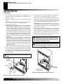
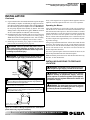
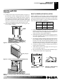
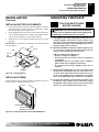
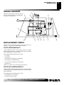
16. Position switch/plate assembly vertically over wall openings
with decal lettering upright (see Figure 13).
17. Insert mounting screws, removed in step 2 of Relocating Wall
Switch on pages 9 and 10, through holes in wall plate and into
wall anchors.
18. Tighten screws until wall plate is firmly attached to wall. Do
not overtighten.
Opening in
Wall or
Mantel Wall
Wall Plate/
Switch
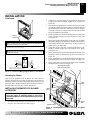
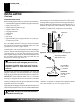
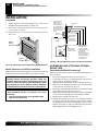
13. Position switch/plate assembly vertically over opening with
decal lettering upright. Make sure wires freely pass through
wall without binding. Align holes in wall plate with 1/8" pilot
holes in mantel wall.
14. Drive mounting screws, removed in step 2 of Relocating Wall
Switch on pages 9 and 10, through wall plate holes and into
pilot holes in mantel wall.
15. Tighten screws until wall plate is firmly attached to mantel.
Do not overtighten.
INSTALLING VARIABLE SPEED BLOWER
ACCESSORY
NOTICE: Shut off gas supply and disconnect heater
from gas supply if installing blower into previously
installed fireplace. Contact a qualified service person
to do this.
Screws
1.
2.
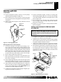
Figure 13 - Securing Wall Switch
3.
Mounting Wall Switch to Side of Mantel
7.
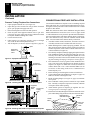
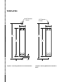
Create three openings in the mantel wall according to Template 2, page 39. This is best done by making a pattern to work
with on the mantel. Carefully cut page 39/40 from manual and
tape paper template vertically onto mantel wall at preferred
location. Pierce the paper at the centers of the 2 holes with a
nail or sharp pencil, leaving a mark on the wall. Do the same
at centers of the four circles near the corners of the rectangle.
8. Remove paper template from mantel wall.
9. Drill 1/8" pilot holes at each mark for top and bottom screw
holes. Drill 3/8" holes at each mark for centers of four circles
near corners of rectangle.
10. Using a straight edge and pencil, connect the outer edges of the 4
holes for the rectangle (see Figure 10, page 10). This will give
you cutting lines for the rectangle you will cut in the mantel wall.
11. Using a keyhole saw, hack saw blade, drill, file, or other suitable tool, carefully cut out the rectangular opening. Note: The
corners of the rectangle may be round. IMPORTANT: Do not
exceed the size of the rectangle on template.
12. Carefully pass switch/plate assembly through rectangular opening from inside mantel (see Figure 13).
4.
If fireplace screen and floor are still installed, see Removing
Fireplace Screen and Floor Assembly, page 8.
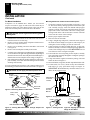
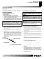
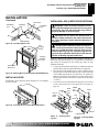
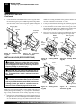
Attach the power cord to the blower motor by firmly pushing
the two female terminals at the end of the power cord onto the
two spade terminals on the blower motor.
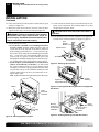
Attach green ground wire from power cord to blower housing
using screw provided (see Figure 14). Tighten screws securely.
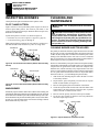
Place the blower against lower rear wall of firebox outer wrapper with the exhaust port directed upward. Align the holes in
top mounting tabs of blower with holes in wall of wrapper
(see Figure 14). Using 2 screws provided, mount blower and
tighten screws securely.
Blower
Lower Rear
Wall of
Firebox
Screws
Exhaust
Port
Top
Mounting
Tab
Screw
Green Ground Wire
Figure 14 - Mounting Blower to Firebox
For more information, visit www.desatech.com
108117-01H