1
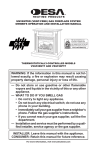
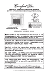
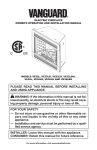
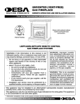
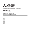
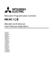
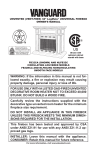
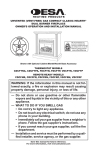
ELECTRIC FIREPLACE/INSERT
26" MODELS CGEF26B, VEF26B, ES301
32" Models CGEF32D, VEF32B
SAFETY INFORMATION AND INSTALLATION MANUAL
Patent No. 7,219,456 B1
Read these instructions completely before beginning
installation. Failure to follow them could cause a heater
malfunction resulting in serious injury and/or property
damage.
WARNING: All electric heaters have hot and arcing
or sparking parts inside. Do not use it in areas where
gasoline, paint or flammable liquids are or are stored.
This fireplace meets the construction and safety standards of H.U.D. for application in manufactured homes
when installed according to these instructions.
INSTALLER: Leave this manual with the appliance.
CONSUMER: Retain this manual for future reference.
For more information, visit www.desatech.com
Table of Contents
Safety................................................................... 2
Listing Approvals.................................................. 3
Product Dimensions............................................. 3
Product Identification............................................ 4
Unpacking and Testing......................................... 4
Locating Fireplace................................................ 4
Installation............................................................ 5
Finishing............................................................... 7
Operation.............................................................. 7
Cleaning and Maintenance................................... 8
Technical Service............................................... 12
Replacement Parts............................................. 12
Troubleshooting.................................................. 13
Wiring Diagram................................................... 14
Accessories........................................................ 15
Parts................................................................... 16
Warranty...............................................Back Cover
Safety
WARNING: Improper installation, adjustment, alteration, service or maintenance can cause
injury or property damage. Refer
to this manual. For assistance or
additional information, consult
a qualified installer.
CAUTION: Do not expose the
heater to the elements (such as
rain, etc).
Do not place clothing or other
flammable material on or near
firebox. Never place any objects
on the fireplace.
Carefully supervise young children when they are in the room
with fireplace.
Fireplace becomes very hot
when running. Keep children and
adults away from hot surfaces to
avoid burns or clothing ignition.
Fireplace will remain hot for a
time after shutdown. Allow surfaces to cool before touching.
Do not install fireplace directly
on carpet or similar surface
which may restrict air circulation
beneath unit.
When using electrical heaters, basic precautions should always be followed to reduce
the risk of fire, electric shock and injury to
persons, including the following:
1. Read all instructions before using this
heater.
2. Keep combustible materials, such as
furniture, pillows, bedding, papers, clothes
and curtains at least 3 feet (0.9 m) from
front of heater.
3. This heater is hot when in use. To avoid
burns, do not let bare skin touch hot surfaces. The grill directly in front of heater outlet
becomes hot during heater operation.
4. Extreme caution is necessary when any
heater is used by or near children or invalids and whenever heater is left operating
and unattended.
5. Always unplug heater when not in use.
6. Do not operate any heater with a damaged
cord or plug or if heater malfunctions or
has been dropped or damaged in any way.
Return heater to authorized service facility
for examination, electrical or mechanical
adjustment or repair.
7. Do not use outdoors.
8. This heater is not intended for use in
bathrooms, laundry areas and similar
indoor locations. Never locate heater
where it may fall into a bathtub or other
water container.
9. Do not run cord under carpeting. Do not
cover cord with throw rugs, runners or the
like. Arrange cord away from traffic area
and where it will not be tripped over.
10.To disconnect heater, turn controls to the
OFF before removing plug from outlet.
11.Do not insert or allow foreign objects to
enter any ventilation or exhaust opening
as this may cause an electric shock or fire
or damage the heater.
12.To prevent possible fire, do not block air
intakes in any manner. Do not use on soft
surfaces, like a bed, where openings may
become blocked.
13.Always use properly grounded fused and
polarized outlets.
www.desatech.com
120927-54B
SAFETY
Continued
14.A heater has hot and arcing or sparking
parts inside. Do not use it in areas where
gasoline, paint or flammable liquids or
vapors are used or stored.
15.Use this heater only as described in this
manual. Any other use not recommended
by the manufacturer may cause fire, electric shock or injury to persons.
16. Avoid the use of an extension cord because the extension cord may overheat
and cause a risk of fire. However, if you
have to use an extension cord, the cord
should be No. 14 AWG minimum size and
rated not less than 1875 WATTS.
17.Always use ground fault protection where
required by electrical codes.
18.Always disconnect power before performing any cleaning, maintenance or relocation of heater.
19.To prevent a possible fire, do not burn
wood or other materials in this heater.
20.To prevent electric shock or fire, always
use a certified electrician should new
circuits or outlets be required.
21.When transporting or storing heater, keep
in a dry place.
22.Control panel door gets hot during heater
operation. Open door by pressing on right
corner. A spring magnet will disengage.
Pull door down to open.
Listing Approvals
This heater has been tested in accordance
with the CSA Standards for fixed and location-dedicated electric room heaters in the
United States. All components are UL or CSA
safety certified.
If you need assistance during installation,
please contact your local dealer or the DESA
Heating Products Technical Services Department at 1-866-672-6040.
Please have the Distributor’s model and serial
numbers when you call.
Description:
Voltage:
Watts:
Amps:
26" and 32" Fireplace/Inserts
120
1500
15 Amp
Grounded Circuit
Note: This heater must be electrically wired and
grounded in accordance with local codes or, in
the absence of local codes, with National Electric
Code ANSI/NFPA 70-latest edition or the Canadian Electric Code, CSA C22.1 as appropriate.
Product Dimensions
9.25"
10"
26"
33.25"
29.25"
37.5"
27"
26" Models
34"
32" Models
Figure 1 - Heater Dimensions
120927-54B
www.desatech.com
Product Identification
Control
Panel Door
Handle
Remote Hide
Magnetic
Catch
Flame Control
Ember Control
Backlight
Control
Heat Vents
(Behind Door)
Front Glass
Heater
Flame
Ember
Backlight
Power
Back Glass
Heater
Control
Remote
ON/OFF
Power
Button
Log Set
Figure 2 - Product Identification
Unpacking and Testing
Carefully remove unit from box. Prior to
permanently installing unit, test to make sure
unit operates properly. To do this, plug unit's
power supply cord into a conveniently located
120-volt grounded outlet.
CAUTION; The unit's power
supply cord must be connected
to a properly grounded and protected 120-volt outlet. Always use
ground fault protection where
required by the electrical code.
WARNING: Do not operate
the unit if it is damaged or has
malfunctioned. If you suspect the
unit is damaged, return the unit
to an authorized service facility
for examination, electrical or mechanical adjustment or repair.
Locating Fireplace
WARNING: Due to high temperatures, this heater should
be located out of traffic. Keep
combustible materials such
as furniture, pillows, bedding,
papers, clothes and curtains at
least 3 feet (0.9 m) from the front
of the heater.
WARNING: Never locate this
heater where it may fall into a bathtub or other water container.
NOTICE: Minimum and maximum
clearances must be maintained at
all times. Illustrations throughout
these instructions reflect typical
installations and are for design
purposes only. Actual installations may vary slightly due to
individual preferences.
WARNING: To prevent
contact with sagging or loose
insulation, the heater must not
be installed against vapor barrier
or exposed insulation. Localized
overheating could occur and a
fire could result.
www.desatech.com
120927-54B
Locating Fireplace
Continued
CAUTION: Do not expose the
heater to the elements (such as
rain, etc.)
Figure 3 illustrates a variety of ways the heater
may be located in a room. The heater may
be installed directly on the floor or raised on
a hearth.
Corner Mantel
Installation
CAUTION: Wear gloves
and safety glasses for protection during installation and
maintenance.
This electric fireplace can be installed in a
mantel, framed into a wall or installed into an
existing fireplace. If installing into a mantel,
follow mantel’s assembly instructions.
Wall Mantel
Installation
Framed
Into Wall
or Existing
Fireplace
Figure 3 - Heater Locations
Installation
WARNING - RISK OF FIRE!
The power cord must not be
pinched or against a sharp edge.
Secure cord to avoid tripping or
snagging to reduce the risk of fire,
electric shock or personal injury.
Do not run cord under carpeting.
Do not cover cord with throw
rugs, runners or the like. Arrange
cord away from traffic areas and
where it will not be tripped over.
WARNING - RISK OF FIRE!
To prevent a possible fire, do
not block air intake or exhaust
in any manner. Do not use on
soft surfaces where openings
may become blocked.
WARNING - RISK OF FIRE!
Do not blow or place insulation
against the firebox.
WARNING: If the information
in these instructions is not followed exactly, a fire or explosion
may result causing property damage, personal injury or death.
120927-54B
Do not store or use gasoline or
other flammable vapors in the vicinity of this or any other heater.
Installing fireplace
Select a suitable location that is not susceptible to moisture and is a safe distance from
drapes, furniture and high traffic areas.
Note: Follow all national and local electrical
codes. This insert can be installed into either
an existing fireplace or as new construction/
renovation.
Installing in Mantel
1. Assemble mantel according to mantel
instructions.
2. Locate mantel near a wall (or corner
depending on mantel type) close to a
power source. You may have to alter base
boards to fit mantel flush against wall.
3. Insert fireplace into front of mantel. Be
careful not to scratch finish on base. Fireplace will fit flush against front of mantel.
4. Plug fireplace into power source. Push
mantel with fireplace into final location.
Existing Fireplace Installation
1. Thoroughly clean out existing fireplace
and hearth area.
2. Seal all drafts, vents or ash clean-outs
with fiberglass insulation. Seal flue. Once
sealed, close damper to stop debris from
falling onto unit.
3. If existing fire box is susceptible to moisture, cap top of chimney flue to prevent
infiltration of water.
www.desatech.com
Installation
Continued
Note: It is strongly advised that you hire
a qualified professional to undertake this
step in order to prevent personal injury.
Once flue is capped, chimney is no longer
suitable for wood burning.
Note: Do not install this unit into a fireplace
that is prone to dampness; the area of installation must be dry.
4. Plan the power supply. If an existing
grounded outlet is near fireplace, power
cord can run along front of fireplace. If
cord is not long enough to reach outlet, a
grounded extension cord minimum AWG
No. 14 and rated to a minimum of 1875
watts, may be used. If you plan to cut or drill
a hole in existing fireplace for wiring, it is
best to hire a professional to do this step in
order to prevent personal injury. To reduce
the risk of fire, do not run power cord under
rugs, carpets, etc. Arrange power supply
cord away from high traffic areas where it
may pose a tripping hazard.
WARNING: The solid fuel/gas
fireplace has been converted for
use with an electric insert and
cannot be used for original fuels
unless all original parts have
been replaced and the fireplace
has been reapproved by the authority having jurisdiction.
New Construction or Renovation
1. Select a location at least 3 feet (0.9 m)
away from combustible materials such
as curtains or drapes, furniture, bedding,
paper, etc.
2. Mark desired location on floor and store
unit in a safe, dry and dust free location.
3. Frame in an opening leaving at least 1/4"
(6 mm) around the edge of the unit (see
Framing). Any new wiring must be done in
compliance with local and national codes
and other applicable regulations in order to
reduce the risk of fire, electric shock or other
injuries. Therefore, it strongly recommended
that you hire a professional to complete any
such work.
4. Plan you power supply route. See step 4
of Existing Fireplace Installation.
Framing
Figure 4, shows a typical framing of this heater
using combustible materials. All required
clearances to combustibles must be adhered
to. Header height is measured from the base
of the heater.
Tools and building supplies required for
installation:
• Saw
• Square
• Pliers
• Gloves
• Hammer
• Level
• Phillips screwdriver
• Surround
• Framing materials
• Electric drill/bits
• Tape measure
• Wall-finishing materials
• Caulking material
Header
Height
Length
Depth
Model Depth Length
26"
32"
9.75"
10.5"
27"
34"
Header
Height
26"
32"
0.75"0.50"
Note: The height that a
combustible mantel is
fitted above the heater is
dependent on the height
of the front selected. The
minimum height is 1" above
the front.
Figure 4 - Framing Heater for New
Construction/Renovation
www.desatech.com
120927-54B
INSTALLATION
Continued
CAUTION: Provide adequate
clearances around the air openings and adequate accessibility
clearances for servicing and
proper operations.
Installing as Insert
Once the site has been prepared, your fireplace insert can be installed.
1. Make sure power switch is in the OFF
position.
2. Plug fireplace into a 15-amp/120 volt,
grounded outlet.
3. Push fireplace insert so trim is against finished mantle or wall surface.
Finishing
WARNING: Control panel door
on this heater cannot, in any way,
be covered as it may create a fire
hazard.
Combustible Finishing Material: Materials
made of or surfaced with wood, compressed
paper, plant fibers, plastics or any material
capable of igniting and burning, whether flame
proofed or not, plastered or unplastered (this
includes drywall).
Noncombustible Finishing Material : Materials which will not ignite and burn. Such
materials are those consisting entirely of
steel, iron, brick, tile, concrete, slate, glass
or plasters or combinations thereof or have a
fire rating of zero.
Finishing checklist
• Power supply service must be completed
prior to finishing to avoid reconstruction.
• Grills and air openings cannot be covered
in any circumstances.
Note: The heater is a zero clearance fireplace
and may be finished with combustible or noncombustible finishing materials.
When using paint or lacquer to finish the
mantel, they must be heat resistant to prevent
discoloration.
Operation
The controls (see Figure 5) are located behind
hinged control panel door. If using heater, control panel door will be hot during and immediately after operation. Open door by pressing
on right side. A spring magnet will push door
forward. Pull door down to open.
1. Plug in electric fireplace.
2. Turn on lighted power switch (see Figure 5).
3. Adjust Flame/Ember/Backlight/Heater
to desired settings using the control pad
on fireplace (Figure 5) or remote control
(Figure 6, page 8). Figure 7, page 8,
shows fireplace settings available. Default
settings are circled. Press control pad or
remote control buttons once and release
to adjust settings.
Note: When on, ember bed will lighten
and darken automatically to simulate real
embers.
The heater is pre-set to the following
temperatures:
High will shut off when room reaches approximately 86° F (30° C).
120927-54B
Medium will shut off when room reaches
approximately 79° F (26° C).
Low will shut off when room reaches approximately 72°F (22° C).
Note: Fan on heater will continue to run
for 5-7 seconds after heater has been
turned off.
4. When using remote control, aim remote
at sensor located in center of unit just
above log set. IMPORTANT: This remote
control must remain within 20 feet (6 m)
of fireplace to be effective.
5. When power switch is turned off, fireplace
settings go back to default (see Figure 7,
page 8).
Heater Flame
Backlight
Ember
Control Control
Control Control
Heater
Flame
Ember
Backlight
Power
Lighted Power Switch
Figure 5 - Controls For Electric Fireplace
www.desatech.com
Operation
Continued
HEATER
Off Low Medium High
FLAME
Off Low Medium High
EMBER
Off Low Medium High
BACKLIGHT
Off Low
High
Figure 7 - Fireplace Settings (Default
Settings are Circled)
Figure 6 - Remote Control For Electric
Fireplace
Cleaning and Maintenance
WARNING: Always disconnect power and allow the heater
to cool before performing any
cleaning, maintenance or relocation of this heater. Turn controls
to OFF and remove plug from
outlet or turn off circuit breaker
to heater.
Glass Bracket
Screws
Screws
To service electric fireplace it may be necessary to remove it from the mantel or enclosure
in which it is installed. Let unit cool completely
before cleaning or servicing.
Control Panel
Door
Magnets on
Back of Trim
Cleaning Firebox
1. Open control panel door by pressing on
right side. A spring magnet will push door
forward. Pull door down to open.
2. Remove 2 screws holding front trim in
place. Pull gently to remove trim (see
Figure 8). There are magnets on the lower
portion of trim (see Figure 8)
3. With gloves and safety glasses in place,
remove 4 screws from glass retainer
brackets (see Figure 8).
4. Carefully remove front glass and brackets
(see Figure 9).
5. Using a brush vacuum attachment, gently
clean compartment.
6. After cleaning compartment, replace front
glass, brackets and trim.
Trim
Figure 8 - Removing Trim
Bracket
Bracket
Front Glass
Figure 9 - Removing Brackets and Front
Glass
www.desatech.com
120927-54B
Cleaning and Maintenance
Continued
Replacing log
1. Follow steps 1 through 4 of Cleaning
Firebox, page 8.
2. Remove screws from each side of log that
secure log to sides and remove log (see
Figure 10).
3. Install new log using screws removed in
step 2.
4. Replace front glass and brackets.
5. Replace trim.
Screw
Ember LED
Strip with
Standoffs
6. Remove brackets from heater/blower (see
Figure 12). Save brackets and screws.
7. To remove heater from blower, remove 4
screws (2 per side).
8. If replacing blower, remove screws from
brackets on blower (see Figure 13,
page 10). Install brackets to new blower.
9. Replace blower or heater. Replace screws
removed in step 7.
10.Hold heater/blower with brackets in place
against top panel and replace screws
removed in step 5.
11.Reconnect wires to main circuit board (see
Wiring Diagram, page 14).
12.Replace glass with brackets, and top
panel.
13.Replace trim.
Top Panel Screws
Screws Securing
Heater/Blower
Log
Figure 10 - Removing Log and Ember
LED
Replacing Ember Strip
1. Follow steps 1 and 2 under Replacing Log.
2. Locate ember LED strip (see Figure 10).
Disconnect wire (right side).
3. Remove ember LED strip by squeezing
top of standoffs and discard.
4. Connect new ember LED strip using existing standoffs.
5. Reconnect wire to LED strip.
6. Follow steps 3 through 5 under Replacing Log.
Figure 11 - Removing Top Panel and
Heater/Blower
Brackets
Replacing Heater/Blower
1. Follow steps 1 and 4 of Cleaning Firebox,
page 8.
2. Remove screws from around top panel of
firebox (see Figure 11).
3. There are several wires attached to the
top panel. Carefully lift top panel.
4. Disconnect heater/blower wires from main
circuit board.
5. Remove screws holding heater/blower to
top panel (see Figure 11).
120927-54B
Figure 12 - Removing Brackets from
Heater/Blower
www.desatech.com
Cleaning and Maintenance
Continued
Blower
Heater
4. Gently push new control board onto
standoffs to install.
5. Reconnect wires to main control board
(see Wiring Diagram, page 14).
6. Replace glass with brackets, and top
panel.
7. Replace trim
Main Control
Transformer
Board
Figure 13 - Removing Heater from
Blower
Standoffs
Replacing Transformer
1. Follow steps 1 through 3 under Replacing
Heater/Blower, page 9.
2. Disconnect transformer wires from control
board.
3. Remove screws and nuts from firebox
surround to remove transformer (see
Figure 14).
4. Remove and discard transformer.
5. Place new transformer against inside of
firebox surround and replace screws and
nuts removed in step 3.
6. Reconnect transformer wires to control
board (see Wiring Diagram, page 14).
7. Replace glass with brackets, and top
panel.
8. Replace trim
Transformer
Screws
Figure 15 - Control Board
Replacing Backlight LED
Strip
1. Follow steps 1 and 3 under Replacing
Heater/Blower, page 9.
2. Disconnect wires from main control
board.
3. Squeeze top of standoffs to remove backlight LED strip and discard.
4. Place new backlight LED strip onto standoffs and push gently.
Nuts
Figure 14 - Removing Transformer
Backlight
LED Strip
Replacing Main Control Board
1. Follow steps 1 through 3 under Replacing
Heater/Blower, page 9.
2. Disconnect wires to main control board.
3. Squeeze top of standoffs to remove main
control board and discard.
10
Standoffs
Figure 16 - Replacing Backlight LED
Strip
www.desatech.com
120927-54B
Cleaning and Maintenance
Continued
5. Connect wires to main control board (see
Wiring Diagram, page 14).
6. Replace glass with brackets, and top
panel.
Replacing Settings Control
Board
1. Follow steps 1 through 3 under Replacing
Heater/Blower, page 9.
2. Disconnect wires from main control
board.
3. Remove screws from bracket to remove
settings control board.
4. Place new settings control board into position making sure each control is aligned
with slot in panel. Install using screws
from step 3. DO NOT overtighten. This
will damage control board.
5. Reconnect wires to main control board
(see Wiring Diagram, page 14).
6. Replace glass with brackets, and top
panel.
7. Replace trim
Screws
5. There are several wires attached to bottom panel. Carefully remove panel.
6. Disconnect wires from motor and LED
drum assembly.
7. Remove screws from bottom panel to
remove assembly.
8. If motor on assembly fails, loosen clamps
(see Figure 18). Remove screws from
motor. Hold universal joint while removing
motor and discard.
9. Install new motor. Slide motor shaft into
universal joint and tighten clamps.
10.Hold LED drum assembly in place on
bottom panel and replace screws.
11.Reattach wires to motor and LED drum.
Note: LED drum wires are polarity sensitive and must be connected correctly.
White wire plugs onto left terminal and red
wire plugs onto right terminal. Motor wires
can be connected to either terminal.
12.Replace fireplace bottom panel. Set fireplace upright and replace screws.
13.Replace log, glass and brackets.
14.Reinstall fireplace and replace trim.
White Wire
Red
Wire
LED Drum
Assembly
Motor
Settings
Control
Board
Screws
Clamps
Figure 17 - Replacing Settings Control
Board
Replacing Flame Generation
LED
1. Follow steps 1 through 4 under Cleaning
Firebox, page 8
2. Remove screws from each side of log that
secure log to base and remove log (see
Figure 10, page 9).
3. Remove screws from sides and back of
bottom panel of firebox.
4. Gently lay unit on its back.
120927-54B
Figure 18 - Flame Generation LED Drum
Assembly
www.desatech.com
11
Cleaning and Maintenance
Continued
Cleaning or Replacing back
screen (Glass)
1. The glass is cleaned in the factory during
assembly. During shipment, installation,
handling, etc. glass surface may collect
dust particles. These can be removed
by buffing lightly with a clean damp cloth
(water only). Glass should be completely
dried with a lint free cloth or paper towel.
2. In the event of glass breakage, vacuum all
remaining glass pieces with a shop vac. DO
NOT VACUUM WHILE PIECES ARE HOT.
Replace glass only with replacement part
specifically for this heater. Never substitute
material. Only fully tempered soda lime
safety glass may be used on this heater.
3. To access glass to clean or replace, follow steps 1 and 7 under Replacing Flame
Generation LED, page 11. Set aside bottom panel.
4. Using gloves, gently remove glass panel
by sliding it toward you. There is a rubber
bumper on each corner of glass.
5. Clean glass as instructed in step 1 or
replace glass.
6. Using gloves, reinstall glass by gently
sliding, smooth side toward fireplace front,
into brackets on either side that hold glass
in place.
7. Replace log base.
8. Follow steps 11 and 14 under Replacing
Flame Generation LED, page 11.
Technical Service
You may have further questions about installation, operation or troubleshooting. If so,
contact DESA Heating Products’ Technical
Service Department at 1-866-672-6040.
When calling please have your DESA model
and serial numbers of your heater ready.
You can also visit DESA Heating Products’
technical services web site at
www.desatech.com.
Replacement Parts
Note: Use only original replacement parts.
This will protect your warranty coverage for
parts replaced under warranty.
Parts Under Warranty
Contact authorized dealers of this product. If
they can’t supply original replacement part(s),
call DESA Heating Products’ Technical Service Department at 1-866-672-6040.
When calling DESA Heating Products, have
ready
• your name
• your address
• DESA (distributor) model number and serial
number of your heater
• how heater was malfunctioning
• purchase date
Usually, we will ask you to return the part to
the factory.
12
Parts Not Under Warranty
Contact authorized dealers of this product. If
they can’t supply original replacement part(s),
call DESA Heating Products at 1-866-672-6040
for referral information.
When calling DESA Heating Products, have
ready
• DESA model number of your heater
• the replacement part number
www.desatech.com
120927-54B
Troubleshooting
WARNING: Turn off appliance and let cool before servicing. Only
a qualified service person should service and repair heater.
OBSERVED PROBLEM
POSSIBLE CAUSE
REMEDY
Fireplace turns off and will not
turn on
1.Fireplace has overheated
and safety devise has cause
thermal switch to disconnect
or home circuit breaker has
opened
1.Reset switch by turning main
power switch off and waiting
5 minutes then turning it back
on or reset circuit breaker
Flame is not moving
1.Loose wiring
1.Inspect wiring for loose
connections
2.Call a qualified service technician to replace flame motor
2.Flame motor defective
Flame is not visible
1.Wiring is loose
1.Disconnect from power
source and inspect wiring for
loose connections and repair
or replace if necessary
Log set and/or ember is not
glowing
1.Wiring is loose
1.Disconnect from power
source and inspect wiring for
loose connections and repair
or replace if necessary
Flame sputters/flashes
1.Flame motor is defective
1.Call a qualified service technician to replace flame motor
2.Disconnect power. Follow
steps to replace flame generation LED. Clean contacts
with dry cloth.
2.Flame generation contacts
dirty/obstructed
Remote control does not work
1.Low batteries
2.Not aiming control correctly
3.Defective remote control
and/or sensor
Fireplace will not come on when
switch is flipped to ON
1.Fireplace is not plugged in
to an electrical outlet
2.Control failure
3.Breaker tripped
Heater does not provide heat
when turned on
1.Thermal switch has been
tripped
2.Circuit breaker has been
tripped
3.Wiring is loose
4.Heater is defective
5.Thermostat cycled off
120927-54B
www.desatech.com
1.Replace AAA batteries in
remote control
2.Aim control at sensor located
directly behind glass screen in
center of unit just above logs
3.Replace remote control and/
or sensor
1.Check plug
2.Call a qualified service technician to replace control
3.Reset breaker
1.Turn unit off and unplug unit
for 5 minutes. Plug back
in and turn unit on. If plug
cannot be reached, follow
directions for tripped circuit
breaker
2.Turn off circuit breaker that
supplies electricity to unit.
Wait 5 minutes then flip circuit breaker back on
3.Disconnect from power
source and inspect wiring for
loose connections and repair
or replace if necessary
4.Replace heater
5.Change to higher setting
13
TF1
TRANSFORMER
BLACK
120V/650W*2 120V/14W
BRW BLU BRW
BROWN
SCT
BROWN
24V/15W
120V/4W
LDA
24V/1W
MTR
LDS
120V/60HZ
RED
WHITE
1
ON/OFF POWER
BLK WHT RED
P/N F801-0015-9000 (Rev. A)
2
24V/0.5W
LBS
RCS
TF
1
1
V36
SCB
26" 32" 36" FIREPLACE MAIN CONTROL BOARD
PCB BOARD AND FUNCTION CONTROL ASSEMBLY
(12V+12V)/700MA
9
9
F801-0017-9000 (Rev. A)
SETTINGS CONTROL BOARD
Wiring Diagram
THM
SCARLET
BLUE
WHITE
BLOWER
SCARLET
Syn. MOTOR
BLUE
BROWN
THERMOCOUPLE
HEATER
POWER CORD SETS
V33
D
HEATER
HEATER/BLOWER
ASSEMBLY
REMOTE
SENSOR
LED
LED FLAME
STRIP
THERMOSTAT
BROWN
BLACK
BLACK
MODEL
MF500
LED EMBER STRIP LED BACKLIGHT
STRIP
14
www.desatech.com
120927-54B
Accessories
Purchase these accessories from your local
dealer. If they can not supply these accessories, call DESA Heating Products Sales
Department at 1-866-672-6040 for information. Always refer to the DESA (distributor)
model number when referencing your heater.
You can also write to the address listed on
back this manual.
26" Wall Mantels with Base
and Trim (For 26" Models)
CMA204FA - Oak, Traditional
CMA210W - White, Traditional
GMC61UD - Unfinished, Slim Line
GMC61D - Dark Espresso, Slim Line
WD26CPA - White, Cottage
WD26GOSA - Dark Oak, Mission
GMC80FB - Light Oak, Georgian
W26LC - Cherry, "Louis Philippe"
W26ME - Espresso, Metropolitan
32" Wall Mantels with Base
and Trim (For 32" Models)
CMA306FA - Oak, Traditional with Dentil
Molding
CMA310F - Cherry, Arched
GMC90FA - Light Oak, Georgian
W32AOSA - Light Oak, Traditional
W32AUA - Unfinished, Traditional
W32GOSA - Dark Oak, Mission
W32KPA - White, Neo-Classical
W32MF - Fruitwood, Metropolitan
W32CC - Cherry, Chateau
32" Corner Mantels with Base
and Trim (For 32" Models)
C32AOSA - Light Oak Traditional
C32AUA - Unfinished Traditional
C32HSA - Dark Oak Classic
26" Corner Mantels with Base
and Trim (For 26" Models)
CMA208FB - Oak, Traditional
GMC63UD - Unfinished, Slim Line
GMC63D - Dark Espresso, Slim Line
GMC83FB - Light Oak, Georgian
120927-54B
www.desatech.com
15
Parts
Models CGEF26B, VEF26B, ES301, CGEF32D and VEF32B
12
19
2
21
18
9
16
5
6
13
7
8
1
14
15
4
17
10
11
3
20
16
www.desatech.com
120927-54B
PARTS
KEY
NO. PART NO.
1
2
3
4
5
6
7
8
9
10
11
12
13
14
15
16
17
18
19
20
21
DESCRIPTION
120925-30
120927-06
120928-06
120927-05
120928-05
120927-07
120928-07
120927-08
120927-09
120927-10
120927-11
120927-12
120927-13
120928-13
120927-14
120927-15
120927-20
120927-21
120927-22
120927-24
120927-03
120928-03
120927-02
120928-02
120927-25
120928-25
120927-01
120928-04
120926-32
Blower
Rear Glass (Screen)
Rear Glass (Screen)
Log Set
Log Set
Flame Effect Mirror
Flame Effect Mirror
Handles
Main Control Board and Standoffs (5)
Transformer
Heater
Settings Control Board
LED Drum Assembly
LED Drum Assembly
Motor (Drum)
LED Ember Strip
Remote Control
Remote Control Sensor
Power Cord
ON/OFF Switch
Front Glass
Front Glass
Control Panel Door (Black)
Control Panel Door (Black)
Top (Black)
Top (Black)
Front Trim
Front Trim
Magnetic Catch
120927-17
120928-17
120927-18
120928-18
120927-19
120928-19
120927-23
Wire (Flame Effect)
Wire (Flame Effect)
Wire (Ember Bed)
Wire (Ember Bed)
Wire (Backlight)
Wire (Backlight)
Thermocouple
CGE
F
VEF 26B,
26B
CGE , ES3
01
F
VEF 32D,
32B
,
This list contains replaceable parts used in your fireplace. When ordering parts, follow the
instructions listed under Replacement Parts on page 12 of this manual.
QTY.
•
•
•
•
•
•
•
•
•
•
•
•
•
•
•
•
•
•
•
•
•
•
•
•
•
•
•
•
•
•
•
•
•
•
•
•
•
•
•
•
•
•
1
1
1
1
1
1
1
2
1
1
1
1
1
1
1
1
1
1
1
1
1
1
1
1
1
1
1
1
1
PARTS AVAILABLE NOT SHOWN
120927-54B
www.desatech.com
•
•
•
•
•
•
•
•
1
1
1
1
1
1
1
17
NOTES
_____________________________________________________
______________________________________________________
______________________________________________________
______________________________________________________
______________________________________________________
______________________________________________________
______________________________________________________
______________________________________________________
______________________________________________________
______________________________________________________
______________________________________________________
______________________________________________________
______________________________________________________
_____________________________________________________
______________________________________________________
______________________________________________________
______________________________________________________
______________________________________________________
______________________________________________________
______________________________________________________
______________________________________________________
______________________________________________________
18
www.desatech.com
120927-54B
NOTES
_____________________________________________________
______________________________________________________
______________________________________________________
______________________________________________________
______________________________________________________
______________________________________________________
______________________________________________________
______________________________________________________
______________________________________________________
______________________________________________________
______________________________________________________
______________________________________________________
______________________________________________________
_____________________________________________________
______________________________________________________
______________________________________________________
______________________________________________________
______________________________________________________
______________________________________________________
______________________________________________________
______________________________________________________
______________________________________________________
______________________________________________________
______________________________________________________
______________________________________________________
______________________________________________________
_____________________________________________________
______________________________________________________
______________________________________________________
______________________________________________________
______________________________________________________
______________________________________________________
______________________________________________________
______________________________________________________
______________________________________________________
120927-54B
www.desatech.com
19
Warranty
KEEP THIS WARRANTY
Model ______________________________
Serial No. ___________________________
Date Purchased ______________________
Always specify model and serial numbers when communicating with the factory.
The only warranty applicable is our standard written warranty. We make no other warranty, expressed or
implied.
LIMITED WARRANTY
ELECTRIC FIREPLACE/INSERT
DESA Heating, LLC warrants this product to be free from defects in materials and components for one
(1) year from the date of first purchase, provided that the product has been properly installed, operated
and maintained in accordance with all applicable instructions. To make a claim under this warranty the
Bill of Sale or cancelled check must be presented.
This warranty is extended only to the original retail purchaser. This warranty covers the cost of part(s)
required to restore this heater to proper operating condition and an allowance for labor when provided by
a DESA Heating, LLC Authorized Service Center. Warranty part(s) MUST be obtained through authorized
dealers of this product and/or DESA Heating, LLC who will provide original factory replacement parts.
Failure to use original factory replacement parts voids this warranty. The heater MUST be installed by
a qualified installer in accordance with all local codes and instructions furnished with the unit.
This warranty does not apply to parts that are not in original condition because of normal wear and tear
or parts that fail or become damaged as a result of misuse, accidents, lack of proper maintenance or
defects caused by improper installation. Travel, diagnostic cost, labor, transportation and any and all
such other costs related to repairing a defective heater will be the responsibility of the owner.
TO THE FULL EXTENT ALLOWED BY THE LAW OF THE JURISDICTION THAT GOVERNS THE SALE
OF THE PRODUCT; THIS EXPRESS WARRANTY EXCLUDES ANY AND ALL OTHER EXPRESSED
WARRANTIES AND LIMITS THE DURATION OF ANY AND ALL IMPLIED WARRANTIES, INCLUDING
WARRANTIES OF MERCHANTABILITY AND FITNESS FOR A PARTICULAR PURPOSE TO ONE
(1) YEAR ON ALL COMPONENTS FROM THE DATE OF FIRST PURCHASE; AND DESA Heating,
LLC’S LIABILITY IS HEREBY LIMITED TO THE PURCHASE PRICE OF THE PRODUCT AND DESA
Heating, LLC SHALL NOT BE LIABLE FOR ANY OTHER DAMAGES WHATSOEVER INCLUDING
INDIRECT, INCIDENTAL OR CONSEQUENTIAL DAMAGES.
Some states do not allow a limitation on how long an implied warranty lasts or an exclusion or limitation
of incidental or consequential damages, so the above limitation on implied warranties or exclusion or
limitation on damages may not apply to you.
This warranty gives you specific legal rights and you may also have other rights that vary from state
to state.
For information about this warranty write:
DESA Heating, LLC
2701 Industrial Drive
P.O. Box 90004
Bowling Green, KY 42102-9004
www.desatech.com
120926 26
NOT A UPC
120927-54
Rev. B
06/07