1
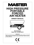
HIGH PRESSURE
PORTABLE
FORCED
AIR HEATERS
OWNER’S MANUAL
600 SIDE
PV 027
350 SIDE
PV 026
Heater Sizes: 350,000 and 600,000 Btu/Hr
Models: B350D and B600D
IMPORTANT: Read and understand this manual before assembling, starting, or servicing heater. Improper use of heater can cause serious injury.
Keep this manual for future reference.
ARL LOGO
®
G 004
HIGH PRESSURE PORTABLE FORCED AIR
HEATER 350,000 AND 600,000 BTU/HR
SAFETY
INFORMATION
WARNING ICON
G 001
WARNINGS
IMPORTANT: Read this Owner’s
Manual carefully and completely
before trying to assemble, operate, or service this heater. Improper use of this heater can
cause serious injury or death from
burns, fire, explosion, electrical
shock, and carbon monoxide
poisoning.
DANGER: Carbon monoxide
poisoning may lead to death!
Carbon Monoxide Poisoning: Early
signs of carbon monoxide poisoning resemble the flu, with headaches, dizziness,
and/or nausea. If you have these signs, the
heater may not be working properly. Get
fresh air at once! Have heater serviced.
Some people are more affected by carbon
monoxide than others. These include pregnant women, persons with heart or lung
disease or anemia, those under the influence
of alcohol, and those at high altitudes.
•
•
•
Make certain you read and understand all
Warnings. Keep this manual for reference.
It is your guide to safe and proper operation
of this heater.
•
•
Use only kerosene or No. 1 fuel oil to
avoid risk of fire or explosion. Never
use gasoline, naphtha, paint thinners,
alcohol, or other highly flammable fuels.
Fueling
a) Personnel involved with fueling shall
be qualified and thoroughly familiar
with the manufacturer's instructions
and applicable federal, state, and local regulations regarding the safe
fueling of heating units.
b)Only the type of fuel specified on the
heater's data plate shall be used.
c) All flame, including the pilot light,
if any, shall be extinguished and the
heater allowed to cool, prior to fueling.
•
•
•
•
d)During fueling, all fuel lines and fuelline connections shall be inspected for
leaks. Any leaks shall be repaired prior
to returning the heater to service.
e) At no time shall more than one day's
supply of heater fuel be stored inside a building in the vicinity of the
heater. Bulk fuel storage shall be
outside the structure.
f) All fuel storage shall be located a
minimum of 25 feet from heaters,
torches, welding equipment, and
similar sources of ignition (exception: the fuel reservoir integral with
the heater unit).
g)Whenever possible, fuel storage
shall be confined to areas where
floor penetrations do not permit
fuel to drip onto or be ignited by a
fire at lower elevation.
h)Fuel storage shall be in accordance
with the federal, state, or local authority having jurisdiction.
Never use heater where gasoline, paint
thinner, or other highly flammable vapors are present.
Follow all local ordinances and codes
when using heater.
Heaters used in the vicinity of tarpaulins, canvas, or similar enclosure materials shall be located a safe distance
from such materials. The recommended
minimum safe distance is 10 feet. It is
further recommended that these enclosure materials be of a fire retardant nature. These enclosure materials shall be
securely fastened to prevent them from
igniting or from upsetting the heater
due to wind action.
Use only in well vented areas. Before
using heater, provide at least a threesquare-foot opening of fresh, outside
air for each 100,000 Btu/Hr of rating.
This heater produces carbon monoxide, which is listed by the State of California as a reproductive toxin under
Proposition 65.
Use only in places free of flammable
vapors or high dust content.
Use only with the electrical voltage and
frequency specified on model plate.
Use only a three-prong, grounded extension cord.
2
•
•
•
•
•
•
•
•
•
•
•
Minimum heater clearances from
combustibles:
Outlet: 8 Ft. Sides: 4 Ft.
Top: 4 Ft. Rear: 4 Ft.
Locate heater on a stable and level
surface while hot or running or a fire
may occur.
When moving or storing heater, keep
heater in a level position or fuel spillage may occur.
Keep children and animals away
from heater.
Unplug heater when not in use.
This heater has a built-in thermostat.
Plugged-in heater may start at anytime.
Never use heater in living or sleeping
areas.
Never block air inlet (rear) or air outlet
(front) of heater.
Never move, handle, refuel, or service
a hot, operating, or plugged-in heater.
Never attach duct work to front or rear
of heater.
Warning to New York City Residents
For Use Only At Construction Sites
in accordance with applicable NYC codes
under NYC Board of Standards and
Appeals calender number 62-59-SA.
099507
OWNER’S MANUAL
PRODUCT
IDENTIFICATION
UNPACKING
1.
2.
3.
Hot Air Outlet
Upper Shell
Motor and
Pump
Assembly
Lower Shell
Fuel Cap
Thermostat
Power Cord
Fuel Tank
Flame-Out Control
Reset Button
Figure 1 - 350,000 Btu/Hr Model
Hot Air Outlet
Upper Shell
Motor and
Pump
Assembly
Lower
Shell
Fuel Cap
Thermostat
Power Cord
Flame-Out Control
Reset Button
Figure 2 - 600,000 Btu/Hr Model
099507
3
Fuel Tank
Remove all protective packing applied
to heater for shipment.
Remove heater from shipping container.
Check heater for any shipping damage.
If heater is damaged, promptly inform
dealer where you bought heater.
HIGH PRESSURE PORTABLE FORCED AIR
HEATER 350,000 AND 600,000 BTU/HR
THEORY OF
OPERATION
FUELS
WARNING: Use only kerosene
or No. 1 fuel oil to avoid risk of fire
or explosion. Never use gasoline, naphtha, paint thinners, alcohol, or other highly flammable
fuels.
The Fuel System: The motor turns the
fuel pump. The fuel pump pulls fuel from
the fuel tank. The fuel pump pushes fuel
through a filter and a solenoid valve and out
the burner head nozzle. A fine mist of fuel is
sprayed into the combustion chamber.
Do not use heavy fuels such as No. 2 fuel oil
or No. 2 diesel. Using heavy fuels will result
in:
• clogged fuel filter and nozzle
• carbon build-up on spark plug
• the need of non-toxic anti-icer in fuel
during very cold weather
The Air System: The motor turns the fan.
The fan pushes air into and around the
combustion chamber. This air is heated and
provides a stream of clean, hot air.
The Ignition System: The electronic ignitor sends voltage to the spark plug. The
spark plug ignites the fuel and air mixture.
IMPORTANT: Use a KEROSENE ONLY
storage container. Be sure storage container
is clean. Foreign matter such as rust, dirt, or
water will cause flame-out control to shut
down heater. Foreign matter may also require you to clean fuel system often.
The Flame-Out Control System: This
system causes the heater to shut down if the
flame goes out. It also allows the fan to
continue running after normal shutdown of
heater. This cools the combustion chamber.
Combustion
Chamber
VENTILATION
Spark
Plug
Solenoid
Valve
Burner
Fan
Head
WARNING: Follow the minimum fresh, outside air ventilation requirements. If proper fresh,
outside air ventilation is not provided, carbon monoxide poisoning can occur. Provide proper
fresh, outside air ventilation before running heater.
Fresh Air Opening
Requirements
Heater Size
Square Feet
Opening
350,000 Btu/Hr
10.5
600,000 Btu/Hr
18.0
Note: If you use more than one heater,
provide extra fresh air. Provide a fresh air
opening of at least three square feet for each
100,000 Btu/Hr rating.
Fuel Pump/
Fuel Filter
Motor
Clean
Heated
Air Out
Cool
Air In
Fuel
Pickup
Line
Fuel Tank
Nozzle
Fuel Line To
Solenoid Valve
Air for Combustion
and Heating
Electronic Ignitor
Fuel
Filter
Fuel
Figure 3 - Cross Section Operational View
4
099507
OWNER’S MANUAL
OPERATION
WARNING: Review and understand the warnings in the
Safety Information Section. They
are needed to safely operate this
heater.
TO START HEATER
1.
2.
3.
4.
5.
Follow all ventilation and safety information.
Fill fuel tank with kerosene or No. 1
fuel oil.
Attach fuel cap.
Set thermostat dial to desired temperature. Note: Thermostat setting must be
higher than surrounding air temperature.
Plug power cord of heater into threeprong, grounded extension cord. Extension cord must be at least six feet long.
WARNING: Use only a threeprong, grounded extension cord.
Use cord with proper wire size to
assure 120 volt operation. See
Extension Cord Wire Size Requirements below.
6.
7.
Extension Cord Wire Size
Requirements
6 to 100 feet long, use 14 AWG rated
cord
101 to 200 feet long, use 12 AWG rated
cord
201 to 300 feet long, use 10 AWG rated
cord
301 to 400 feet long, use 8 AWG rated
cord
401 to 500 feet long, use 6 AWG rated
cord
Plug extension cord into standard 120
volt/60 hertz, three-hole, grounded outlet.
The motor will start when extension
cord is plugged into outlet. The heater
should ignite at once. If heater does not
ignite, restart heater. To restart heater,
wait 60 seconds, then push in flameout control reset button. Flame-out control reset button is at rear of heater near
power cord (see Figure 4).
099507
Note: A cold heater may affect the termostat
setting. This thermostat is a general-heating
control. It is not intended for precise temperature control. Adjust thermostat until
heater cycles at the desired setting.
Note: If starting heater for first time, you
may need to restart heater several times
before heater ignites. You may also have to
do this after taking heater out of storage. To
facilitate starting, remove the canister bottom from the pump's fuel filter and fill with
fuel. Reassemble filter (see Pump Fuel
Filter, page 12).
Flame-Out Control
Reset Button
Figure 4 - Flame-Out Control Reset Button
TO STOP HEATER
CAUTION: Never unplug
heater while heater is running.
Heater must go through purge
cycle. The purge cycle cools the
combustion chamber. Damage to
heater can occur if combustion
chamber is not cooled. Do not
restart heater until purge cycle is
complete.
1.
2.
3.
Turn thermostat dial to lowest temperature setting. This will cause heater
flame to go out. The motor will continue to run during the purge cycle. This
allows the fan to cool the combustion
chamber. When the purge cycle is
finished, the motor will stop. Do not
unplug heater until purge cycle is finished.
Unplug extension cord from outlet.
To temporarily stop heater, set thermostat at a temperature lower than air
around heater. Heater will cycle back
on if air temperature around heater
matches thermostat setting.
5
TO RESTART HEATER
CAUTION: Do not restart
heater until purge cycle is
finished. The purge cycle cools
the combustion chamber.
1.
2.
Wait until purge cycle is finished after
stopping heater.
Repeat steps under To Start Heater.
STORING,
TRANSPORTING,
OR SHIPPING
Note: If shipping transport companies require fuel tanks to be empty.
1. Drain all fuel from fuel filters, fuel
lines, and pump (see Fuel Filters [Tank
Fuel Filter], page 12).
2. Clean and flush fuel filter and canister
attached to fuel pump (see Fuel Filters
[Pump Fuel Filter], page 12).
3. Remove drain plug and drain fuel tank.
4. Replace drain plug.
5. If any debris is noted in old fuel, add 1
or 2 quarts of clean kerosene to tank,
stir, and drain again. This will prevent
excess debris from clogging filters during future use.
6. Replace fuel cap or drain plug. Properly dispose of old and dirty fuel. Check
with local automotive service stations
that recycle oil.
7. Add two gallons (350,000 Btu/Hr) or
three gallons (600,000 Btu/Hr) of clean
kerosene or No. 1 fuel oil to fuel tank.
8. Replace fuel cap.
9. Operate heater for 5 minutes (see
Operation).
10. Stop heater and let cool completely.
11. Remove drain plug and drain fuel tank.
12. Replace drain plug.
13. Properly dispose of old and dirty fuel.
14. If storing, store heater in a dry location. Make sure storage place is free of
dust and corrosive fumes.
IMPORTANT: Do not store kerosene over
summer months for use during next heating
season. Using old fuel could damage heater.
HIGH PRESSURE PORTABLE FORCED AIR
HEATER 350,000 AND 600,000 BTU/HR
PREVENTATIVE
MAINTENANCE
SCHEDULE
WARNING: Never service
heater while it is plugged in, operating, or hot. Severe burns and
electrical shock can occur.
Item
How Often
How To
Fuel tank
Flush every 150-200 hours of operation or
as needed
See Storing, Transporting, or Shipping,
page 5
Filler neck screen
Check for particles in fuel when filling fuel
tank. Clean when dirty
Lift out of fuel tank and rinse with clean
kerosene
Fuel filter assembly (Fuel tank)
Clean twice a heating season or replace as
needed
See Fuel Filters, page 12
Fuel filter lines
Check and tighten loose connections occasionally
See Fuel Lines, Page 12
Fuel filter (Pump)
Clean fuel filter element every 250 hours
See Fuel Filters, page 12
Spark plug
Clean and regap every 300 hours of operation or replace as needed
See Spark Plug, page 10
Fan blades and air deflectors
Clean each season or as needed
See Fan Blades and Air Deflectors, page 10
Air passages around burner head
Check each season for dirt and debris
Remove debris and trash with a clean, soft cloth
Motor
Not required, permanently lubricated
6
099507
OWNER’S MANUAL
TROUBLESHOOTING
WARNING: Never service heater while it is plugged in, operating, or
hot. Severe burns and electrical shock can occur. Only a qualified service
person should service and repair heater.
Note: For additional help, visit DESA
International’s Technical Service web
site at www.desatech.com.
OBSERVED PROBLEM
POSSIBLE CAUSE
REMEDY
Motor does not start when heater is plugged
in and thermostat setting is higher than
surrounding air temperature
1. No power or low voltage at heater due
to:
A) Damaged power cord or extension cord
B) Wrong size extension cord
C) Heater plugged into outlet with voltage lower than 120 volt
1. A) Check condition of power cord or
ex tension cord. Repair or replace
damaged
B) Use extension cord with proper wire
size (see To Start Heater, page 5)
C) Make sure heater is plugged into 120
volt/60 hertz outlet
2. Check connections. Tighten if loose
3. A) See Fan Blades and Air Deflectors,
page 10
B) Remove debris from fan and fan
guard area
C) Turn fan by hand. If fan is hard to
turn, see Pump, page 11
D) See steps B and C under item 1 above
2. Loose electrical connections
3. Motor overload protector tripped due to:
A) Dirty fan
B) Debris pulled into fan area by fan
C) Binding pump
D) Low voltage
4. Flame-out control not reset
4.
5.
6.
7.
8.
5.
6.
7.
8.
Damaged flame-out control
Damaged power relay
Damaged thermostat
Binding pump
www.desatech.com
099507
7
Note: Be sure to reset motor overload
protector by pressing reset button on top
of motor.
Press and release flame-out control reset button. See Figure 4, page 5 for button location
Replace flame-out control
Replace power relay
Replace thermostat
Turn fan by hand. If fan is hard to turn,
see Pump, page 11
Continued
HIGH PRESSURE PORTABLE FORCED AIR
HEATER 350,000 AND 600,000 BTU/HR
TROUBLESHOOTING
Continued
OBSERVED PROBLEM
POSSIBLE CAUSE
REMEDY
Heater will not ignite, but motor runs for a
short period of time
1. A) Fuel tank empty
B) Water in fuel
C) Wrong fuel
1. A) Add fuel to tank.
B) Check fuel tank for bubbles of water
in bottom. If found, remove fuel (see
Storing, Transporting, or Shipping,
page 5). Clean tank and fuel filters
(see Fuel Filters, page 12). Fill with
clean fuel.
C) Remove wrong fuel (see Storing,
Transporting, or Shipping, page 5).
Clean tank and fuel filters (see Fuel
Filters, page 12). Fill with correct fuel
2. Replace nozzle (see Nozzle, page 10)
3. Move heater to warmer place until fuel
flows freely
4. Clean fuel filters (see Fuel Filters, page 12)
5. Adjust pump pressure (see Pump Pressure Adjustment, page 11)
6. Connect spark plug wire to spark plug
7. A) Adjust electrode gap to .075" (see
Spark Plug, page 10)
B) Clean fuel from spark plug with
clean, soft cloth
C) Replace plug if heavily coated with
carbon (see Spark Plug, page 10)
D) Inspect plug for worn or eroded elec
trodes. If found, replace plug (see
Spark Plug, page 10)
8. Check electrical connections and voltage to solenoid. If good, replace solenoid valve
2. Dirt in nozzle
3. Very low temperature may cause fuel to
thicken and not flow
4. Dirty fuel filters
5. Wrong pump pressure
6. Spark plug wire disconnected from plug
7. Spark plug problems due to:
A) Wrong gap
B) Plug wet with fuel
C) Carbon deposits on plug
D) Damaged plug
8. Solenoid valve not opening
WARNING: High Voltage!
9. Damaged electronic ignitor
9. Replace electronic ignitor
www.desatech.com
8
099507
OWNER’S MANUAL
TROUBLESHOOTING
Continued
OBSERVED PROBLEM
POSSIBLE CAUSE
REMEDY
Heater ignites, but flame-out control shuts
off heater after a short period of time
1. Wrong pump pressure
1. Adjust pump pressure (see Pump Pressure Adjustment, page 11)
2. Clean fuel filters (see Fuel Filters,
page 12)
3. Replace nozzle (see Nozzle, page 10)
4. Clean photocell lens with clean cotton
swab
5. Replace photocell
6. Replace flame-out control
7. Replace fan switch
2. Dirty fuel filters
3. Dirt in nozzle
4. Dirty photocell lens
5. Open or damaged photocell
6. Bad flame-out control
7. Damaged fan switch
Heater burns, but puffs of smoke can be seen
Heater does not burn steady
Heater burns with odor
Heater smokes continuously
1. Wrong pump pressure
1. Adjust pump pressure ( see Pump Pressure Adjustment, page 11)
2. A) Heater almost out of fuel
B) Water condensation in fuel tank
C) Wrong fuel
2. A) Add fuel to tank
B) Check fuel tank for bubbles of water
in bottom. If found, remove fuel (see
Storing, Transporting, or Shipping,
page 5). Clean tank and fuel filters
(see Fuel Filters, page 12). Fill with
clean fuel
C) Remove wrong fuel (see Storing,
Transporting, or Shipping, page 5).
Clean tank and fuel filters (see Fuel
Filters, page 12. Fill with correct fuel
3. Clean fuel filters (see Fuel Filters,
page 12)
4. Tighten all fuel line connections (see
Fuel Lines, page 12)
5. Replace nozzle (see Nozzle, page 10)
6. Check voltage at heater. Voltage at heater
should be not less than 90% of rated voltage (108V minimum for 120V heaters)
7. Check and tighten all fuel line connections (see Fuel Lines, page 12)
3. Dirty fuel filters
4. Air leak in suction system
5. Dirty nozzle
6. Low voltage causing motor to operate
below rated speed
7. Loose fuel line
www.desatech.com
099507
9
HIGH PRESSURE PORTABLE FORCED AIR
HEATER 350,000 AND 600,000 BTU/HR
SERVICE
PROCEDURES
NOZZLE
Air Deflector
1.
2.
WARNING: Never service
heater while it is plugged in, operating, or hot. Severe burns and
electrical shock can occur. Only
a qualified service person should
service and repair heater.
3.
4.
5.
UPPER SHELL REMOVAL
1.
2.
Remove screws along each side and top
of heater using 5/16" nut-driver. These
screws attach upper and lower shells
together (see Figure 5).
Lift upper shell off.
Upper Shell
6.
Fan Blade
7.
Figure 6 - Fan Blades and Air Deflectors
8.
SPARK PLUG
1.
2.
3.
4.
5.
6.
7.
8.
Remove upper shell (see column 1).
Remove spark plug wire from spark
plug (see Figure 7).
Remove spark plug from burner head
using 13/16" open-end wrench (see
Figure 7).
Replace spark plug if damaged or
heavily coated with carbon.
Clean and regap spark plug electrodes
to .075 inch (see Figure 8).
Install spark plug in burner head.
Attach spark plug wire to spark plug.
Replace upper shell.
9.
10.
11.
12.
13.
14.
15.
Remove upper shell (see column 1).
Remove fuel line from solenoid valve
using 7/16" wrench.
Remove spark plug wire from spark plug.
Remove spark plug from burner head
using 13/16" open-end wrench.
Remove five screws using 5/16" nutdriver and remove burner head from
combustion chamber.
Place burner head into vise and
lightly tighten.
Carefully remove nozzle from burner
head using 5/8" socket wrench (see Figure 9, page 11).
Inspect nozzle for damage. If damaged
or clogged, replace nozzle.
Make sure plug is in place on burner head.
Replace nozzle into burner head and
tighten firmly (175-200 inch-pounds).
Attach burner head to combustion
chamber.
Install spark plug in burner head.
Attach spark plug wire to spark plug.
Attach fuel line to solenoid valve.
Tighten firmly.
Replace upper shell.
Burner Head
Spark Plug
Figure 5 - Upper Shell Removal, 600,000
Btu/Hr Model
FAN BLADES AND AIR
DEflECTORS
1.
2.
3.
4.
Remove upper shell (see column 1).
Clean fan blades and air deflectors with
clean, soft cloth moistened with kerosene or solvent (see Figure 6).
Dry fan blades and air deflectors thoroughly.
Replace upper shell.
Spark
Plug Wire
Figure 7 - Spark Plug Removal
.075
inch
Figure 8 - Spark Plug Gap
10
099507
OWNER’S MANUAL
PUMP
SERVICE
PROCEDURES
(Procedure if Pump is Binding)
1.
2.
Continued
Nozzle
Plug
Spark
Plug
3.
4.
5.
6.
Solenoid
Valve
Burner
Head
Remove upper shell (see page 10).
Loosen hex screw on flange clamp at
rear of motor with 5/16" nut-driver (see
Figure 11).
Turn fan with hand (see Figure 12).
If fan turns freely, tighten screw on
flange clamp.
If fan does not turn freely, replace pump.
Replace upper shell.
Spark
Plug
Wire
Hex Screw
On Flange
Clamp
Fuel
Line
Figure 9 - Replacing Nozzle
Pump Pressure Adjustment
1.
Remove pressure gage plug from fuel
pump port marked “GAGE.”
Install accessory pressure gage (part
number M4574) to fuel pump port
marked “GAGE” (see Figure 10).
2.
Pressure
Gage
3.
4.
5.
6.
Start heater (see Operation, page 5).
Allow motor to reach full speed.
Adjust pressure. Use small flat blade
screwdriver to turn slotted screw at fuel
pump port marked “PRESS ADJ.” Turn
screw clockwise to increase pressure.
Turn screw counterclockwise to decrease pressure. See specifications at
right for correct pressure for each model.
Stop heater (see page 5).
Remove pressure gage. Replace pressure gage plug in fuel pump port
marked “GAGE.”
Figure 11 - Location of Screw on Flange
Clamp
Figure 12 - Turning Fan with Hand
i
ps
Fuel Pump Port
Marked “GAGE”
Fuel Pump Port
Marked “PRESS
ADJ”
Model
350,000 Btu/Hr
600,000 Btu/Hr
Pump Pressure
100 PSI
110 PSI
Figure 10 - Adjusting Pump Pressure
Continued
099507
11
HIGH PRESSURE PORTABLE FORCED AIR
HEATER 350,000 AND 600,000 BTU/HR
SERVICE
PROCEDURES
FUEL FILTERS
Continued
1.
1.
A. Tank Fuel Filter
FUEL LINES
(Procedure for Tightening
Fuel Lines)
2.
1.
2.
3.
4.
3.
B. Pump Fuel Filter
Remove upper shell (see page 10).
Use an adjustable wrench as a backup
on 90° fittings.
Use 7/16" wrench and tighten fuel
lines at solenoid valve (see Figure
13), pump, and pump fuel filter assembly (see Figure 14).
Burner Head
5.
6.
Disconnect fuel lines from pump and
pump fuel filter assembly with 7/16"
wrench (see Figure 15).
Carefully pry fuel filter loose from fuel
tank with flat end of screwdriver.
Inspect fuel filter for water or dirt.
Rinse fuel filter and fuel lines with
clean kerosene.
Replace fuel filter into fuel tank.
Connect fuel lines to pump and pump
fuel filter assembly.
Pump Fuel
Filter
Assembly
2.
3.
4.
5.
6.
7.
8.
9.
Unscrew canister bottom from canister top with adjustable pliers.
Remove fuel filter and gasket from canister bottom (see Figure 16).
Inspect canister bottom and fuel filter
for water droplets or dirt.
Rinse canister bottom in clean kerosene.
Wipe inside of canister bottom dry with
clean cloth.
Rinse fuel filter in clean kerosene.
Put clean fuel filter and gasket back in
canister bottom.
Screw canister bottom into canister top.
Tighten securely.
Canister Top
Fuel
Lines
Fuel
Line
Solenoid
Valve
Gasket
Fuel Filter
Figure 13 - Fuel Line at Solenoid Valve
Fuel Filter
Pump
Fuel Filter
Assembly
Figure 15 - Removing Tank Fuel Filter
Canister
Bottom
Pump
Figure 16 - Fuel Pump Filter and Canister
Fuel
Lines
Figure 14 - Fuel Lines at Pump and Pump
Fuel Filter Assembly
12
099507
OWNER’S MANUAL
SPECIFICATIONS
350,000 Btu/Hr
600,000 Btu/Hr
350,000
600,000
Use Only Kerosene or No. 1 Fuel Oil
30
36
2.5
4
120V/60 Hz
120V/60 Hz
7.1
11
1725
1725
100
110
.075"
.075"
180
285
390
550
Output Rating (Btu/Hr)
Fuel
Fuel Tank Capacity (U.S. Gallons)
Fuel Consumption (Gallons Per Hr)
Electric Requirements
Amperage (Normal Run)
Motor RPM
Fuel Pump Pressure (PSI)
Spark Plug Gap
Weight (approx. lbs.) Dry
With Full Fuel Tank
WIRING DIAGRAM
BLACK
7
THERMOSTAT
5
B
BLACK
B
WHITE
A
RED
RELAY
Flame-Out Control
Spark Plug
HA3003
HA3012
ACCESSORY
Purchase this heater accessory from your
nearest dealer or service center. If they cannot supply this accessory, either contact
your nearest Parts Central or DESA
International's Parts Department at 1-800972-7879 for information. Parts Centrals
are listed in the Authorized Service Center
booklet supplied with heater. You can also
write to the address listed on the back page
of this manual.
MOTOR
RED
BLACK
YELLOW
RED
TERMINAL
TERMINAL
BOARD
BOARD
WHITE
FUEL PRESSURE GAGE
M4574
WHITE
YELLOW
BLACK
2
SPARK
PLUG
WHITE
WHITE
FAN
SWITCH
3
RED
TECHNICAL
SERVICE
ELECTRONIC
IGNITOR
BLACK
GREEN
WHITE
120V
60Hz
ORANGE
Special tool to check fuel pump pressure
YELLOW
SOLENOID
VALVE
WHITE
BLUE
PHOTOCELL
You may have further questions about installation, operation, or troubleshooting.
If so, contact DESA International’s Technical Service Department at 1-800-323-5190.
You can also visit DESA International’s
Technical Services web site at
www.desatech.com.
Figure 17 - Wiring Diagram
099507
Part Number
ORANGE
WHITE
PLUG
Kit
RESET
FLAME-OUT
CONTROL R BUTTON
BLUE
WHITE
1
MAINTENANCE
KITS
13
HIGH PRESSURE PORTABLE FORCED AIR
HEATER 350,000 AND 600,000 BTU/HR
ILLUSTRATED
PARTS
BREAKDOWN
2
1
2
350,000 BTU/HR
3
4
5
21
2
9
6
7
8
19
10
20
14
4
21
13
22
11
12
15
25
13
16
23
17
26
31
30
28
27
18
24
29
20
41
32
34
2
33
34
39
35
2
36
38
37
4
40
37
14
099507
OWNER’S MANUAL
PARTS LIST
This list contains replaceable parts used in your heater. When ordering parts, follow the instructions listed
under Repair Service on the back page of this manual.
350,000 BTU/HR
REF.
NO.
PART NO.
DESCRIPTION
1
2
3
4
5
6
7
8
9
10
11
12
13
14
15
16
17
18
19
20
21
22
23
24
25
26
27
28
29
30
31
32
33
34
35
36
37
38
39
40
41
099329-02
M11084-27
M50542-01
M30865-02
M50086
†
M16656-18
M50121
M50097-01AA
M51336-02
M51160-01
M50278
M11084-26
†
099896-01
M50295
M50050
102482-04
099329-01
M11271-8
M11084-3
M50104-02
099509-01
M50115-01
M50062-03
097702-01
HA2210
HC4-18C
M51043-01
M50062
098513-05
M50063
M18774
NTC-4C
M50389
C5-10C
WP-10C
M50296
M27417
099895-01
M11084-29
Upper shell model B350D (Yellow)
Screw, #10-16 x 1/2"
Combustion chamber & shield
Bushing
Air deflector
Burner head assembly
Photocell assembly
Fan
Fan guard
Fan switch
Fan switch cover
Sleeve
Screw, #10-16 x 3/8"
Motor & pump assembly
Power cord
Fuel line
Ignition boot
Electronic Ignitor
Lower shell model B350D (Yellow)
Clip nut
Screw, #12-14 x 1/2"
Bushing
Wire harness
Fuel line assembly
Front handle
Fuel cap
Filler neck screen
Screw, 1/4-20 x 2 1/4"
Screw, 1/4-20 x 1 1/2"
Rear handle
Fuel tank
Wheel support frame
Axle
Hex lock nut, 1/4-20
Wheel
Cotter pin, 5/32 x 1 1/4"
Flatwasher, 5/8"
Wheel spacer
Drain plug
Thermostat
Screw, #10-16 x 3/4"
†Not available as complete assembly. See page 18.
099507
15
QTY.
1
15
1
7
5
1
1
1
1
1
1
1
13
1
1
1
1
1
1
16
14
2
1
1
1
1
1
6
2
1
1
1
1
8
2
2
4
2
1
1
2
HIGH PRESSURE PORTABLE FORCED AIR
HEATER 350,000 AND 600,000 BTU/HR
ILLUSTRATED
PARTS
BREAKDOWN
1
2
600,000 BTU/HR
2
3
4
5
9
13
2
6
8
45
7
15
10
46
16
14
4
13
12
11
17
18
24
19
2
21
23
4
22
25
20
28
26
31
27
32
33
34
30
25
29
47
16
35
37
2
36
15
38
15
39
41
40
42
44
43
2
43
16
099507
OWNER’S MANUAL
PARTS LIST
600,000 BTU/HR
This list contains replaceable parts used in
your heater. When ordering parts, follow
the instructions listed under Repair Service
on the back page of this manual.
REF.
NO.
1
2
3
4
5
6
7
8
9
10
11
12
13
14
15
16
17
18
19
20
21
22
23
24
25
26
27
28
29
30
31
32
33
34
35
36
37
38
39
40
41
42
43
44
45
46
47
PART NO.
DESCRIPTION
099329-04
M11084-27
M50543-01
M30865-02
M50157
†
104679-01
M50194
M50186-01AA
M51336-02
M51160-01
M50278
M11084-26
†
NTC-4C
M11271-8
M11084-3
M50104-02
099329-03
M50119-01
099896-01
M50388AB
HC4-3C
M50224
M51043-01
097702-01
HA2210
099509-02
M28872-01
M50115-02
M50050
102482-04
098513-07
HC4-22C
M28140-02
M18774
M27417
RC1-3C
099895-01
M25121B
M50389
C5-10C
WP-10C
M50296
104413-01
M10908-2
M11084-29
**
NPC-1C ∆
Upper shell model B600D (Yellow)
Screw, #10-16 x 1/2"
Combustion chamber & shield
Bushing
Air deflector
Burner head assembly
Photocell assembly
Fan
Fan guard
Fan switch
Fan switch cover
Sleeve
Screw, #10-16 x 3/8"
Motor & pump assembly
Hex nut, 1/4-20
Clip nut
Screw, #12-14 x 1/2"
Bushing
Lower shell model B600D (Yellow)
Fuel line
Power cord
Support bracket model B600D (Yellow)
Screw, 1/4-20 x 3/8"
Front handle
Screw, 1/4-20 x 1 1/2"
Fuel cap
Filler neck screen
Wire harness
Rear handle
Fuel line assembly
Ignition boot
Electronic Ignitor
Fuel tank
Screw, 1/4-20 x 2 3/4"
Wheel support frame
Axle
Drain plug
Screw, #6-32 x 3/8"
Thermostat
Thermostat bracket (Black)
Wheel
Cotter pin, 5/32 x 1 1/4"
Flatwasher, 5/8"
Wheel spacer
Photocell Bracket
Screw, #6-32 x 3/8"
Screw, #10-16 x 3/4"
Internal lockwasher No. 6
Nut, 6-32
† Not available as complete assembly. See page 18.
∆ Not shown.
** Standard hardware item
099507
17
QTY.
1
28
1
5
5
1
1
1
1
1
1
1
15
1
18
18
4
2
1
1
1
2
4
1
6
1
1
1
1
1
1
1
1
8
1
1
1
2
1
1
2
2
4
2
1
2
2
2
2
HIGH PRESSURE PORTABLE FORCED AIR
HEATER 350,000 AND 600,000 BTU/HR
Burner Head Assembly 350,000 and 600,000 Btu/Hr
REF
NO.
PART NO.
DESCRIPTION
1
M10908-2
Screw, #6-32 x 3/8"
(350,000 Btu/Hr Only)
Photocell bracket
(350,000 Btu/Hr Only)
Spark plug
Nozzle (350,000 Btu/Hr)
Nozzle (600,000 Btu/Hr)
Plug
Burner head body
Straight nipple
Solenoid valve
Compression elbow
2
3
4
5
6
7
8
9
099229-01
HA3012
M50112
M30765
M51170-01
M50924-02
69246
M50077
M50297
3
QTY.
1
2
1
1
1
1
1
1
1
1
1
4
5
2
6
7
8
9
Figure 18 - Burner Head Assembly
Motor and Pump Assembly 350,000 and 600,000 Btu/Hr
REF.
NO.
1
2
3
4
5
6
7
8
9
10
11
12
13
14
15
16
17
18
19
20
21
22
23
24
25
PART NO.
DESCRIPTION
097495-02AA
HF5-5C
WLE-5
M11084-26
099562-01
099562-02
M50116
Wiring cover
Screw, 5/16-24 x 5/16"
External lockwasher, 5/16"
Screw, #10-16 x 3/8"
Motor (350,000 Btu/Hr)
Motor (600,000 Btu/Hr)
Flange clamp
(holds pump to motor)
099520-01AA Motor support
(350,000 Btu/Hr)
101552-01
Motor support
(600,000 Btu/Hr)
57413
Street elbow
M17499-2
Pipe nipple
098102-01
Fuel filter assembly
098103-01
Filter element
(inside fuel filter
assembly, includes
rubber gaskets)
M50114-02
90˚ Male elbow
M50297
Compression elbow
M50113-02
Straight fitting
098560-01
Fuel pump
**
Lockwasher, 5/16"
NPF-5C
Hex nut, 5/16-24"
HA3003
Flame-out control
097491-01
Power relay
101547-01
Snap bushing
M10908-2
Screw, #6-32 x 3/8"
101504-01
Strain relief bushing
M10908-14
Screw, #8-32 x 3/8"
099125-05
Terminal board
099125-04
Terminal board
099157-01
Rivet
1
QTY.
1
4
4
3
1
1
4
2
3
1
11
5
10
1
9
6
1
2
1
1
8
14
12
13
1
1
1
1
1
4
4
1
1
3
2
1
1
1
1
2
20
8
19
(3)
22
18
17
21
7
24
23
15
16
25
(2)
Figure 19 - Motor And Pump Assembly
** Standard hardware item
18
099507
OWNER’S MANUAL
NOTES
_______________________________________________________________________________________________
_______________________________________________________________________________________________
_______________________________________________________________________________________________
_______________________________________________________________________________________________
_______________________________________________________________________________________________
_______________________________________________________________________________________________
_______________________________________________________________________________________________
_______________________________________________________________________________________________
_______________________________________________________________________________________________
_______________________________________________________________________________________________
_______________________________________________________________________________________________
_______________________________________________________________________________________________
_______________________________________________________________________________________________
_______________________________________________________________________________________________
_______________________________________________________________________________________________
_______________________________________________________________________________________________
_______________________________________________________________________________________________
_______________________________________________________________________________________________
_______________________________________________________________________________________________
_______________________________________________________________________________________________
_______________________________________________________________________________________________
_______________________________________________________________________________________________
_______________________________________________________________________________________________
_______________________________________________________________________________________________
_______________________________________________________________________________________________
_______________________________________________________________________________________________
_______________________________________________________________________________________________
_______________________________________________________________________________________________
_______________________________________________________________________________________________
_______________________________________________________________________________________________
_______________________________________________________________________________________________
_______________________________________________________________________________________________
_______________________________________________________________________________________________
_______________________________________________________________________________________________
099507
19
WARRANTY AND REPAIR SERVICE
PARTS AND SERVICE UNDER
WARRANTY
LIMITED WARRANTY
DESA International warrants this product and any parts
thereof, to be free from defects in materials and workmanship for one (1) year from the date of first purchase when
operated and maintained in accordance with instructions.
This warranty is extended only to the original retail purchaser, when proof of purchase is provided.
This warranty covers only the cost of parts and labor required to restore the product to proper operating condition.
Transportation and incidental costs associated with warranty repairs are not reimbursable under this warranty.
Warranty service is available only through authorized dealers and service centers.
This warranty does not cover defects resulting from misuse,
abuse, negligence, accidents, lack of proper maintenance,
normal wear, alteration, modification, tampering, contaminated fuels, repair using improper parts, or repair by anyone
other than an authorized dealer or service center. Routine
maintenance is the responsibility of the owner.
THIS EXPRESS WARRANTY IS GIVEN IN LIEU OF
ANY OTHER WARRANTY EITHER EXPRESSED OR
IMPLIED, INCLUDING WARRANTIES OF MERCHANTABILITY AND FITNESS FOR A PARTICULAR
PURPOSE.
DESA International assumes no responsibility for indirect,
incidental or consequential damages. Some states do not
allow the exclusion or limitation of incidental or consequential damages, or limitations or exclusions may not apply to
you. This Limited Warranty gives you specific legal rights
and you may also have other rights which vary from state to
state.
Should your heater require service, return it to your nearest
authorized service center. Proof of purchase must be presented
with the heater. The heater will be inspected. A defect may be
caused by faulty materials or workmanship. If so, DESA International will repair or replace the heater without charge. If they
cannot supply original replacement part(s), either contact your
nearest Parts Central or call DESA International’s Technical
Service Department at 1-800-323-5190.
When calling DESA International, have ready
• your name
• your address
• model number of your heater
• how heater was malfunctioning
• proof of purchase
Usually, we will ask you to return the defective part to the factory.
PARTS AND REPAIR SERVICE
Return your heater to your nearest authorized service center.
Repairs not covered by the warranty will be billed at standard
prices. If they cannot supply original replacement part(s), either
contact your nearest Parts Central or call DESA International’s
Parts Department at 1-800-972-7879 for information.
When calling DESA International, have ready
• model number of your heater
• the replacement part number
A service manual may be purchased from the address listed
below. Send a check for $5.00 payable to DESA International.
When writing for information regarding your heater, be sure to
include the model number and serial number as shown on the
model plate.
Each service center is independently owned and operated.
We reserve the right to amend these specifications at any time
without notice.
KEEP THIS WARRANTY
Model No. _______________________________
Serial No. _______________________________
Date of Purchase _________________________
(To be filled in by purchaser)
Corporate Headquarters
2701 Industrial Drive
P.O. Box 90004
Bowling Green, Kentucky 42102-9004
www.desatech.com
099507 01
NOT A UPC
For information, write: DESA International, P.O. Box 90004
Bowling Green, Kentucky 42102-9004 ATTN: Customer Service Department
When writing, always include Model number and Serial number.
099507-01
Rev. L
06/99