1
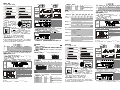
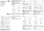
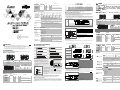
Model
Power
Input unit
Points
DVP32HN00R
Type
Output unit
Points
0
DVP32HP00R
32
16
DVP48HP00R
24
100 ~ 240V
AC
DVP32HN00T
0
MP U
24
32
DVP32HP00T
16
16
DVP48HP00T
24
24
Transistor: 5 ~ 30V DC 0.3A/1 point at 40°C
Specifications
Model
08HM11N
16HM11N
Power supply voltage
08HN11R/T 08HP11R/T 16HP11R/T 32HN00R/T
24V DC (20.4 ~ 28.8V DC) (-15% ~ 20%)
Power consumption
32HP00R/T
48HP00R/T
100~240V AC (-15%~10%), 50/60Hz ± 5%
1W/1.5W
1.5W
1.5W
2W
30VA
30VA
30VA
NA
NA
NA
NA
NA
500mA
500mA
24V DC supply current
Model
Output
points
Power protection
24V DC output with short-circuit protection
Voltage withstand
1,500V AC (Primary-secondary), 1,500V AC (Primary-PE), 500V AC (Secondary-PE)
Insulation resistance
> 5 MΩ at 500V DC (Between all input/output and earth)
Noise immunity
ESD: 8KV Air Discharge, EFT: Power Line: 2KV, Digital I/O: 1KV, Analog &
Communication I/O: 250V,
Digital I/O: 1KV, RS: 26MHz ~ 1GHz, 10V/m
Grounding
The diameter of grounding wire cannot be smaller than the wire diameter of the terminals Land
N (All DVP units should be grounded directly to the ground pole.)
Environment
Operation: 0°C ~ 55°C (temperature), 50 ~ 95% (humidity), Pollution degree 2;
Storage: -25°C ~ 70°C (temperature), 5 ~ 95% (humidity)
MPU
16EH/32EH/64EH
8/16/32
8/16/32
X0~X7/X0~X17/X0~X37
Y0~Y7/Y0~Y17/Y0~Y37
EXT1
32HP
16
16
X20~X37/X20~X37/X40~X57
Y20~Y37/Y20~Y37/Y40~Y57
EXT2
48HP
24
24
X40~X67/X40~X67/X60~X107
Y40~Y67/Y40~Y67/Y60~Y107
EXT3
08HP
4
4
X70~X73/X70~X73/X110~X113
Y70~Y73/Y70~Y73/Y110~Y113
EXT4
08HN
0
8
-
Vibration/shock
resistance
Standard: IEC61131-2, IEC 68-2-6 (TEST Fc)/IEC61131-2 & IEC 68-2-27 (TEST Ea)
Weight (g)
124/160
Active level
Reaction time
Circuit isolation
/operation indicator
Power Input Wiring and Specification
130/120
136/116
225/210
5
Voltage specification
Below 250V AC, 30V DC
660/590
438/398
616/576
1
4
5
7
5
4
30V DC
9W
Off→On 15us
7
3
3
DVP08HM11N
Length
Width
Height
90
40
82
DVP16HM11N
90
55
82
DVP08HN11R/T
90
40
82
On→Off 25us
90
55
82
X0 X2
X 4 X6
S/S X1 X3
Y0 Y1 Y3
Y4 Y5 Y7
C0 Y2
C1 Y6
X 5 X7
Y0 Y1 Y 3
C0 Y2
S /S X 0 X1
X2 X 3 X4 X5
C0
Y1
Y2
DVP-16HP (8in/8out)
S /S X4 X5 X6 X7
Y4 Y5 Y 6 Y 7
X0 X 1 X 2 X3
C 0 Y 0 Y 1 Y2 Y3
DVP-32HP(16in/16out)
(AC Power IN,DC Signal IN)
Y4 Y5 Y7 Y1 0 Y11 Y13 Y1 4 Y1 5 Y17
C1 Y6
C2 Y1 2
C3 Y16
Y3
C2
Y5
Y7 Y11 C3
Y6 Y10 Y12
Y16
C4
Y21 Y22 Y23 Y25
Y20
C5 Y24
Y1 Y3
C0 Y2
Y4 Y5 Y7 Y10 Y11 Y13 Y14 Y15 Y17 Y20 Y22 Y24 Y26
C1 Y6
C2 Y12
C3 Y16 C4 Y21 Y23 Y25 Y27
9
2
8
6
1
6
Model
Length
Width
Height
DVP32HN00R/T
90
143.5
82.2
DVP32HP00R/T
90
143.5
82.2
DVP48HP00R/T
90
174
82.2
4
10
11
3
3
3
7
1. Power, low voltage indicators
5. Extension wiring
9. Cover
2. I/O terminals
6. Extension port cover
10. Input indicators
3. DIN rail clip
7. Direct mounting holes
11. Output indicators
4. DIN rail
8. Model name
DVP EH Series Model
Model
Power
DVP08HM11N
Input unit
Points
DVP16HM11N
0
DVP08HP11R
4
24V DC
8
Points
0
16
DVP08HN11R
DVP16HP11R
Type
8
Output unit
0
Type
N/A
8
DC Type
Sink/Source
4
Relay: 250V AC/30V DC 2A/1point
8
DVP08HN11T
0
8
DVP08HP11T
4
4
DVP16HP11T
8
8
Transistor: 5 ~ 30V DC 0.3A/1point at 40°C
9
D V P MP U
Environment:
1. DO NOT store the PLC in an airborne dust, smoky, metallic particles, corrosive or flammable gases.
2. DO NOT store the PLC in a location where temperatures and humidity will exceed specification.
3. DO NOT mount the PLC in a location where vibration and shock will exceed specification.
I/O Point Serial Sequence
長
尺寸 (mm)
寬 (w)
高
DVP32HN00R/T
90
143.5
82.2
DVP32HP00R/T
90
143.5
82.2
DVP48HP00R/T
90
174
82.2
6
機種名稱
3
3
3
7
電源、低電壓指示燈
輸出 入端子
軌固定扣
軌固定槽
1.
2.
/
3. DIN
4. DIN
機種型號
機種
5.
6.
7.
8.
電源
點數
擴充排線
擴充機連接口上蓋
直接固定孔
機種名稱
輸入單元
形式
9.
10.
11.
8
DVP16HM11N
16
DVP08HN11R
0
8
DVP08HP11R
4
4
24V DC
0
0
DC Type
Sink/Source
8
S/S X0
X1
X2
Sink Type
Input point loop equivalent circuit
Wiring loop
SOURCE
+24V
+5V
24G
SOURCE Mode
(Current flows out of
common terminal S/S)
S/S
+24V 24G
S/S X0
X1
X0
Source Type
Relay output wiring
C0
Y0
C1
Y1
Y2
C2
2
8
3
9
Y4
Y3
MC2
5
X2
Y5
1
MC1
2
7
MC1
5
MC2
7
6
4
10
DO NOT wire to the No Function terminals
•
Fuse
Diode in reverse direction to protect the relay*1
Mutually exclusive outputs*2
Emergency stop: use an external switch
Surge absorber*3
Conductive loading
Incandescent lamp (resistive loading)
DC supply
AC supply
*1: There is no protection circuit for the Relay output in the PLC. If DC conductive loading is on, add a diode in reverse direction in
parallel to extend the life of the Relay. The diode in reverse direction should correspond to the following specification:
- The diode is able to withstand 5~10+ times loading voltage as maximum.
- The forward current of the diode must be greater than loading current.
*2: Use external hardware interlock and those in the PLC program to secure any emergent errors with safety protection.
*3: There is no protection circuit for the Relay in the PLC. If AC conductive loading is on, connect a surge absorber (0.1uF+ “100ohm to
120ohm”) to reduce interference and extend the life of the Relay.
Transistor output wiring
C0
Y0
C1
Y1
C2
Y2
Y3
MC2
5
7
3
8
Y4
Y5
1
MC1
6
MC1
MC2
3
6
4
DO NOT wire to the No Function terminals
•
Emergency stop
Fuse
Mutually exclusive output*1
DC apply
Incandescent lamp (resistive loading)
Diode in reverse direction to protect the transistor*2
Conductive loading
Resistive loading
*1: Use external hardware interlock and those in the PLC program to secure any emergent errors with safety protection.
*2: Use Zener diode (39V) inside the PLC to protect the transistor. If conductive loading is on, adding a diode in reverse direction in
parallel is recommended.
輸入單元
形式
@40°C
0
32
16
16
DVP48HP00R
24
24
100 ~ 240V
AC
DC Type
Sink/Source
0
輸出單元
形式
點數
DVP32HP00R
繼電器 Relay 250V AC/30V DC 2A/1 點
電晶體 Transistor 5 ~ 30V DC 0.3A/1 點
@40°C
32
DVP32HP00T
16
16
規格
24
24
電氣規格
機種
項目
電源電壓
消耗電力
24V DC 供應電流
24V DC 輸出具短路保護
突波電壓耐受量
絕緣阻抗
雜訊免疫力
接地
操作/儲存環境
耐振動/衝擊
重量(約)(g)
認證
電晶體 Transistor 5 ~ 30V DC 0.3A/1 點
8
點數
DVP48HP00T
+24V 24G
繼電器 Relay 250V AC/30V DC 2A/1 點
8
DVP32HN00R
DVP32HN00T
Wiring loop
電源
上蓋
輸入指示燈
輸出燈示燈
輸出單元
形式
無
點數
DVP08HM11N
機種
+5V
X0
9
When connecting MPU with less than 32 points to extension unit, the input number of 1 extension unit is
started from X20 in sequence and the output number is started from Y20 in sequence. If connecting MPU with
more than 32 points to extension unit, the input number of the 1st extension unit is started from the last input
number of the MPU in sequence and the output number is started form the last output number of the MPU in
sequence.
6
1
11
SINK
24VDC
2
st
8
10
S/S
> 5 0 mm
•
2
4
X0
> 5 0 mm
Dimension (mm)
82
82
Source = Current flows out of common terminal S/S
S/S
82
40
55
4
Output Point Wiring
DIN Rail Installation:
For heat dissipation. Make
The DVP-PLC can be secured to a cabinet by using the DIN
sure to provide a minimum
rail that is 35mm high with a depth of 7.5mm. When
clearance of 50mm between
mounting the PLC on the DIN rail, be sure to use the end
the unit and all sides of the
bracket to stop any side-to-side motion of the PLC, thus to
cabinet. (shown as below)
reduce the chance of the wires being pulled loose. On the
bottom of the PLC is a small retaining clip. To secure the
PLC to the DIN rail, place it onto the rail and gently push up
on the clip. To remove it, pull down on the retaining clip and
gently pull the PLC away from the DIN rail. Please see the
figure on the right:
Direct Mounting: Use the specified dimensions and install with M4 screws.
1. Please use O-type or Y-type terminals for I/O wiring terminals. The
specification for the terminals is as shown on the left. PLC terminal screws
Wiring:
should be tightened to between 5 ~ 8 kg-cm (4.3 ~ 6.9 in-lbs). Use copper
conductor only, 60°C/75°C.
2. DO NOT wire to the No Function terminals
. I/O signal wires or power
Below 6.2
supply should not run through the same multi-wire cable or conduit.
3.
When
tightening
the
screws
and
performing
wiring,
please avoid that
To suit M3.5 screw terminal
metallic particles fall into PLC. After completing wiring, please remove the
label which is used to obstruct the metallic particles on the ventilation hole
Below 6.2
for well heat dissipation.
4. There should be a 50mm or more distance between the PLC and other
control component. Also, keep the PLC away from high voltage line and
power equipment.
55
90
90
8
DC Type
(DC Signal IN)
DVP-48HP(24in/24out)
Y0
90
DVP16HP11R/T
8
Y26 Y27 Y31 Y32 Y34 Y36
C6 Y30 C7 Y33 Y35 Y37
(AC Power IN,DC Signal IN)
82
DVP16HP11T
S/S X0 X2 X4 X6 X10 X12 X14 X16 X20 X22 X24 X26
X1 X3 X5 X7 X11 X13 X15 X17 X21 X23 X25 X27
48HP
40
There are SINK and SOURCE types for the input signal of the input point with DC input. Definition as follows:
DVP-32HN(32out)
(AC Power IN)
32HN
高
90
4
SINK Mode
(Current flows into the
common terminal S/S)
X14
X15
尺寸 (mm)
寬
0
24VDC
Y4
長
DVP08HN11R/T
24G
X6 X7
C1
3
DVP08HP11T
DVP-16HM (16in)
S/S X10 X 11 X12 X13 X 14 X15 X16 X 17
7
3
DVP08HN11T
+24V
1
3
DVP16HP11R
Input point loop equivalent circuit
7
7
Input/Output Point Wiring
DC Type
(DC Signal IN)
16HM
X0 X2
S /S X 1 X3
5
Input Point Wiring
08HN
2
5
4
1
DVP16HM11N
+5V
Sourcing
> 5 0mm
6
7
X2
AC: 100 ~ 240V AC, 50/60Hz
DC: 24V DC
> 5 0 mm
DVP16HP11R/T
6
DVP-08HN (8out)
Mounting Arrangements and Wiring Notes
Dimension (mm)
Model
X1
DVP PLC MPU (main processing unit)
Class three grounding.
Power supply:
7
N
6
X0
Y0 Y1 Y3
C0 Y2
X0
electromagnetic contactor and the relay to be the isolation unit of
the power circuit to prevent the possible instability of the system
when the power is supplied on and off.
MC
S/S
S/S X0 X2 X4 X6 X1 0 X12 X14 X16
X1 X3 X5 X7 X11 X13 X15 X1 7
3
S/S
Sinking
1
7
3
Sink = Current flow into common terminal S/S
DVP-08HM (8in)
32HP
3
L
24 VDC OV
Digital I/O Terminal Wiring
4
1
+24V 24G
Circuit isolation device (System Power Disconnect): use
1
Transistor-T
55°C 0.1A/1point, 50°C 0.15A/1point,
45°C 0.2A/1point, 40°C 0.3A/1point (2A/COM)
7
5
機種名稱
to disconnect system power.
2
Guard
Lim it
75VA (inductive)
90W (resistive)
About 10ms
2
3
Power supply for AC loads
Fuse for circuit protection (3A limit)
Power on pilot indicator
Emergency stop: a manual stop button is provided for emergency
8
Installation and Wiring
16HP
5
The +24V supply output is rated at 0.5A as max. from MPU. DO NOT connect external power
supply to this termianl. Moreover, it takes 6 ~ 7mA to drive each input point, so total of 100mA
is needed for 16 input points. As a result, the output load of +24V should not exceed 400mA.
Photocoupler/LED On
08HP
7
N
DC/DC
5
DVP-08HP (4in/4out)
2
產品外觀及各部介紹
4
2.0 A
AC Input
MC
1.5A/1point (5A/COM)
Thank you for choosing Delta DVP-EH series PLC. The main processing units offer 8 ~ 48 points and the
maximum input/output can be extended up to 256 points.
2
DVP08HM11N
L
DC
DC (SINK or SOURCE)
24V DC 5mA
Off→On, above 16.5V DC
On→Off, below 8V DC
About 20ms
Current specification
Reaction time
5
產品簡介
謝謝您採用台達 DVP-EH 可程式控制器。EH 8 ~ 48 點擴充,含主機最大數位輸入/輸出擴充分別可達 256 點。
Since the PLC is in control of numerous devices, operation of either one device could affect the operation of
other devices; therefore, the breakdown of either one device would consequently be detrimental to the whole
auto control system, and danger will thus be resulted. Please use the recommended wiring below for the power
input:
Relay-R
Maximum load
Product Profile and Outline
6
Output point
Output point type
Introduction
Y74~Y103/Y74~Y103/Y114~Y123
The power input for DVP-EH series PLC is AC input. Please pay particular attention to the following notes:
1. Connect the AC input (100 ~ 240V) to terminals L and N. Any 110V AC or 220V AC connected to the +24V
terminal or input points will permanently damage the PLC.
2. The AC power inputs for the MPU and the I/O Extension Unit should be ON or OFF at the same time.
3. Please use wires of 1.6mm or above for the grounding of the MPU.
4. If the power-cut time is less than 10ms, the PLC still operates unaffectedly. If the power-cut time is too long or
the power voltage drops, the PLC will stop operation and all outputs will be off. Once power is on again, the
PLC will resume automatically. (There are latched auxiliary relays and registers inside of the PLC, please be
aware when programming.)
Input point
08HM
繁體中文
請在使用之前,詳細閱讀本使用說明書。
本機為開放型 (OPEN TYPE) 機殼,因此使用者使用本機時,必須將之安裝於具防塵、防潮及免於電擊/衝擊
意外之外殼配線箱內。另必須具備保護措施 (如: 特殊之工具或鑰匙才可打開) 防止非維護人員操作或意外衝
擊本體,造成危險及損壞。
交流輸入電源不可連接於直流類型之輸入/出信號端,否則可能造成嚴重的損壞,因此請在上電之前再次確認
電源配線。請勿在上電時觸摸任何端子。
7
Input point type
Input type
Input current
Always read this instruction sheet thoroughly before using DVP EH digital I/O extension unit.
This is an OPEN TYPE extension unit. The extension unit should be kept in an enclosure away from airborne, dust,
high humidity, electric shock risk and vibration. Also, it is equipped with protective methods such as special tools or
keys to open the enclosure, so as to avoid the hazard to users and damage the extension unit.
DO NOT connect AC main circuit power supply to any of the input/output terminals, as it will damage the extension
unit. Check all the wiring prior to power up. DO NOT touch terminals when power on.
Type
I/O Terminal Specification
ENGLISH
Output number
100~240VAC
Approvals
Warning
Input number
In system application example, if the input/output of the 1st MPU are less than 16, its input/output will be defined
as 16 and thus there are no corresponding input/output for higher numbers. The input/output number of
extension number is the sequential number from the last number of the MPU.
Electrical Specification
Item
PLC
Input
points
Relay: 250V AC/30V DC 2A/1point
16
DC Type
Sink/Source
注意事項
EXT1 EXT2 EXT3 EXT4
Type
輸入/出點規格
輸入點形式
輸入形式
輸入電壓電流
動作位準
反應時間
電路隔離/操作指示
輸出點形式
電流規格
電壓規格
最大負載
反應時間
08HM11N
16HM11N
08HN11R/T 08HP11R/T 16HP11R/T 32HN00R/T 32HP00R/T 48HP00R/T
24V DC (20.4V DC ~ 28.8V DC) (-15% ~ 20%)
100 ~ 240V AC (-15% ~ 10%),
50/60Hz ± 5%
1W / 1.5W
1.5W
1.5W
2W
30VA
30 VA
30 VA
NA
NA
NA
NA
NA
500 mA
500 mA
輸出具短路保護
5 MΩ 以上(所有輸出/入點對地之間 500V DC)
24V DC
1,500V AC (Primary-secondary), 1,500V AC (Primary-PE), 500V AC (Secondary-PE)
ESD: 8KV Air Discharge, EFT: Power Line: 2KV, Digital I/O: 1KV, Analog &
Communication I/O: 250V,
Digital I/O: 1KV, RS: 26MHz ~ 1GHz, 10V/m
接地配線之線徑不得小於電源端 L, N 之線徑(多台 PLC 同時使用時,請務必單點接地)
操作:0 ~ 55°C(溫度), 50 ~ 95%(濕度), 污染等級 2
儲存:-25 ~ 70°C(溫度),5 ~ 95%(濕度)
國際標準規範 IEC61131-2, IEC 68-2-6 (TEST Fc)/IEC61131-2 & IEC 68-2-27 (TEST Ea)
124/160
130/120
136/116
225/210
660/590
438/398
616/576
輸入點電氣規格
直流
直流(SINK 或 SOURCE)
24V DC 5mA
以上
以下
Off → On 16.5V DC
On → Off 8V DC
約 20ms
光耦合器/LED On
輸出點電氣規格
繼電器-R
電晶體-T
55°C 0.1A/1 點、50°C 0.15A/1 點、
1.5A/1 點(5A/COM)
45°C 0.2A/1 點、40°C 0.3A/1 點(2A/COM)
250V AC,30V DC 以下
30V DC
75VA(電感性)
9W
90 W(電阻性)
約 10 ms
Off → On 15us
On → Off 25us
安裝及配線
數位 I/O 擴充機之端子配置圖
Sink = 電流流入共用端 S/S
Source = 電流流出共用端 S/S
S/S
X0
DVP-08HM (8in)
X0 X 2
DVP-08HN (8out)
Y0 Y1
X5 X7
C0
DVP-08HP (4in/4out)
Y3
Y4 Y5
Y2
S/S X0 X1
C0 Y2
X2 X3 X 4 X5
C0
Y2
DVP-16HP (8in/8out)
16HP
S/S X4 X5 X6 X7
Y4 Y5 Y6 Y7
X0 X1 X2 X3
C0 Y0 Y1 Y2 Y3
Y16
Y21 Y22 Y23 Y25
C4 Y20
C5 Y24
Y4
Y3
Y5
+ 24V
C2 Y7 Y11 C3
Y6 Y10 Y12
X14
X15
SINK
48HP
(AC Power IN,DC Signal IN)
Y4 Y5 Y7 Y1 0 Y11 Y13 Y1 4 Y1 5 Y17
C1 Y6
C2 Y1 2
C3 Y16
輸入點回路等效電路
5 0mm
DVP MPU
50 mm
50 mm
50 mm
6.2
M3.5
6.2
輸出入點序號排列
MPU
PLC
機種
SOURCE
+ 5V
24G
模式
MPU
16EH/32EH/64EH
8/16/32
8/16/32
EXT1
32HP
16
16
輸入點編號
輸出點編號
X0~X7/X0~X17/X0~X37
Y0~Y7/Y0~Y17/Y0~Y37
X20~X37/X20~X37/X40~X57
Y20~Y37/Y20~Y37/Y40~Y57
EXT2
48HP
24
24
X40~X67/X40~X67/X60~X107
EXT3
08HP
4
4
X70~X73/X70~X73/X110~X113 Y70~Y73/Y70~Y73/Y110~Y113
08HN
0
8
-
Y40~Y67/Y40~Y67/Y60~Y107
電源端配線及規格
MC2
5
2
3
1
MC1
7
MC1
5
MC2
7
6
4
10
C0
Y0
C1
Y1
Y2
C2
5
7
Y4
Y3
MC2
L
交流電源
輸入型式
N
+24V 24G
2
S/S
X0
X1
简体中文
请在使用之前,详细阅读本使用说明书。
本机为开放型 (OPEN TYPE) 机壳,因此使用者使用本机时,必须将之安装于具防尘、防潮及免于电击/
冲击意外之外壳配线箱内。另必须具备保护措施 (如: 特殊之工具或钥匙才可打开) 防止非维护人员操作或
意外冲击本体,造成危险及损坏。
交流输入电源不可连接于直流类型之输入/出信号端,否则可能造成严重的损坏,因此请在上电之前再次确
认电源配线。请勿在上电时触摸任何端子。
產品簡介
2
5
5
1
4
8
2
Guard
Limit
MC
3
1
7
N
6
況發生時,切斷系統電源。
使用電磁接觸器、繼電器等開關作為系統電
源回路隔離裝置,可防止電源斷續供應時,造成系統的不穩定。
DVP PLC 本體
第三種接地,接地阻抗 100Ω 以下
電源供應:
交流 (AC): 100 ~ 240V AC, 50/60Hz
直流 (DC): 24V DC
系統回路隔離裝置:
MC
輸入點之入力信號為直流電源 DC 輸入,DC 型式共有兩種接法:SINK 及 SOURCE,其定義如下:
08HN11R/T 08HP11R/T 16HP11R/T 32HN00R/T 32HP00R/T 48HP00R/T
7
7
3
3
尺寸 (mm)
宽
长
1W/1.5W
1.5W
1.5W
2W
30VA
30VA
30VA
NA
NA
NA
NA
NA
500mA
500mA
DC24V
输出具短路保护
1,500V AC(Primary-secondary), 1,500V AC(Primary-PE), 500V AC(Secondary-PE)
5 MΩ
以上 (所有输出/入点对地之间 500V DC)
ESD: 8KV Air Discharge, EFT: Power Line: 2KV, Digital I/O: 1KV, Analog &
Communication I/O: 250V,
Digital I/O: 1KV, RS: 26MHz~1GHz, 10V/m
接地配线之线径不得小于电源端 L, N 之线径(多台 PLC 同时使用时,请务必单点接地)
操作:0°C ~ 55°C 温度 50 ~ 95% 湿度 污染等级 2;
储存:-25°C ~ 70°C 温度 5 ~ 95%(湿度
国际标准规范 IEC61131-2, IEC 68-2-6 TEST Fc /IEC61131-2 & IEC 68-2-27(TEST Ea)
(
(
),
(
90
40
82
DVP16HM11N
90
55
82
DVP08HN11R/T
90
40
82
DVP16HP11R/T
90
55
82
2
8
6
1
),
130/120
136/116
)
225/210
10
11
3
3
3
高
DVP32HN00R/T
90
143.5
82.2
DVP32HP00R/T
90
143.5
82.2
DVP48HP00R/T
90
174
82.2
7
电源、低电压指示灯
输出 入端子
轨固定扣
轨固定槽
1.
2.
/
3. DIN
4. DIN
机种型号
机种
5.
6.
7.
8.
电源
扩充排线
扩充机连接口上盖
直接固定孔
机种名称
点数
输入单元
形式
9.
10.
11.
DVP16HM11N
16
0
DVP08HN11R
0
8
DVP08HP11R
4
4
8
0
DC Type
Sink/Source
上盖
输入指示灯
输出灯示灯
输出单元
形式
无
点数
8
DVP16HP11R
438/398
616/576
输入点电气规格
直流
直流(SINK 或 SOURCE)
继电器 Relay 250V AC /30V DC 2A/1 点
8
DVP08HN11T
0
8
DVP08HP11T
4
4
DVP16HP11T
8
8
晶体管 Transistor 5 ~ 30V DC 0.3A/1 点
@40°C
EXT1
32HP
16
EXT2
48HP
24
EXT3
08HP
EXT4
08HN
EXT1 EXT2 EXT3 EXT4
输入点数 输出点数
输入点编号
输出点编号
X0~X7/X0~X17/X0~X37
Y0~Y7/Y0~Y17/Y0~Y37
16
X20~X37 / X20~X37/X40~X57
Y20~Y37/Y20~Y37/Y40~Y57
24
X40~X67/X40~X67/X60~X107
Y40~Y67/Y40~Y67/Y60~Y107
4
4
X70~X73/X70~X73/X110~X113
Y70~Y73/Y70~Y73/Y110~Y113
0
8
-
Y74~Y103/Y74~Y103/Y114~Y123
电源端配线及规格
系列 PLC 电源输入为交流输入,在使用上应注意下列事项:
交流电源输入电压,范围宽广(100V AC ~ 240V AC),电源请接于 L,N 两端,如果将 110V AC 或 220V AC 接至
+24V 端或输入点端,将使 PLC 损坏,请使用者特别注意。
2. 主机及 I/O 扩展机之交流电源输入请同时作 On 或 Off 的动作。
3. 主机之接地端使用 1.6mm 以上之电线接地。
4. 当停电时间低于 10ms 时,PLC 不受影响继续运行,当停电时间过长或电源电压下降将使 PLC 停止运行,输出
全部 Off, 当电源恢复正常时,PLC 亦自动回复运行。( PLC 内部具有停电保持的辅助继电器及缓存器,使用
者在作程序设计规划时应特别注意使用)
DVP-EH
1.
100~240VAC
L
交流电源
输入型式
N
S/S
4
8
2
G ua rd
Lim it
MC
3
MC
1
L
24 V D C O V
7
N
6
6
输入/出点之配线
交流电源负载
电源回路保护用保险丝 (3A)
电源指示灯
紧急停止:为预防突发状况发生,设置一紧急停止按钮,可在状
况发生时,切断系统电源。
系统回路隔离装置:使用电磁接触器、继电器等开关作为系统电
源回路隔离装置,可防止电源断续供应时,造成系统的不稳定。
DVP PLC 本体
第三种接地,接地阻抗 100Ω 以下
电源供应:
交流 (AC): 100 ~ 240V AC, 50/60Hz
直流 (DC): 24V DC
输入点之配线
输入点之入力信号为直流电源 DC 输入,DC 型式共有两种接法:SINK 及 SOURCE,其定义如下:
Sink =
电流流入共享端 S/S
Source =
X0
Sinking
S/S
DVP-08HN (8out)
Sourcing
Y0 Y1 Y3
Y4 Y5 Y7
C0 Y2
C1 Y6
DVP-08HP (4in/4out)
直流形式
Y0 Y1 Y 3
C0 Y2
X2 X 3 X4 X5
C0
S /S X4 X5 X6 X7
Y4 Y5 Y 6 Y 7
X0 X 1 X 2 X3
C 0 Y 0 Y 1 Y2 Y3
Y4
Y3
C2
Y5
Y7 Y11 C3
Y6 Y10 Y12
X14
X15
SINK
DVP-32HN(32out)
(AC Power IN)
32HN
Y16
C4
Y21 Y22 Y23 Y25
Y20
C5 Y24
DVP-32HP(16in/16out)
(AC Power IN,DC Signal IN)
Y4 Y5 Y7 Y1 0 Y11 Y13 Y1 4 Y1 5 Y17
C1 Y6
C2 Y1 2
C3 Y16
+24V
输入点回路等效电路
Y1 Y3
C0 Y2
S/S
X0
X1
X2
配线回路
Sink Type
SOUR CE
+24 V
24VDC
(DC Signal IN)
(AC Power IN,DC Signal IN)
Y0
24G
X0
+ 5V
24G
S/S
Y4 Y5 Y7 Y10 Y11 Y13 Y14 Y15 Y17 Y20 Y22 Y24 Y26
C1 Y6
C2 Y12
C3 Y16 C4 Y21 Y23 Y25 Y27
盘内安装及配线
SOURCE
+24V
模式
5 0m m
D VP M PU
5 0m m
5 0m m
6.2
M3.5
使用 32 点点数以下的主机连接扩展,所连接的第一台扩展,输入点编号由 X20 依序排列,输出点编号亦由 Y20
开始依序排列,使用 32 点点数以上的主机连接扩展,所连接的第一台扩展,输入点编号以主机最后编号依序排
列,输出点编号亦由主机最后编号依序排列,若使用者所连接的系统如下:
24 G
S/S
X0
X1
X2
X0
Source Type
输出点之配线
5 0m m
输出入点序号排列
模式
DVP-48HP(24in/24out)
铝轨之安装方法:
PLC 在安装时,请装配于封闭式之
控制箱内,其周围应保持一定之空
适合 35mm 之 DIN 铝轨,主机欲挂于铝轨时,先将 PLC
间(如下图所示),以确保 PLC 散热
下方之固定塑料片压入,再将 PLC 由上方挂上再往下压
功能正常。
即可。欲取下 PLC 时,PLC 底部下之固定塑料片,以起
子插入凹槽,向上撑开即可,该固定机构塑料片为保持型,
以上
当所有的固定片撑开后,再将 PLC 往上外方取出,如右
以上
以上
图所示:
以上
直接锁镙丝方式:请依产品外型尺寸并使用 M4 镙丝。
配线:
1. 出/入配线端请使用 O 型或 Y 型端子,端子规格如左所示。PLC 端子镙丝扭力
为 5 ~ 8 kg-cm (4.3 ~ 6.9 in-lbs)。只能使用 60/75°C 的铜导线。
以下
2. 空端子 • 请勿配线。输入点信号线与输出点等动力线请勿置于同一线糟内。
使用 3. 锁镙丝及配线时请避免微小的金属导体掉入 PLC 内部,并在配线完成后,将位
于 PLC 上方散热孔位置的防异物掉入之贴纸撕去,以保持散热良好。
以下
4. PLC 与其它之控制组件应保持 50mm 以上之间隔,并应远离高压线及动力设备。
使用环境:
1. 请勿将 PLC 装置于落尘大、油烟、金属性粉尘及腐蚀性或可燃性气体的环境当中。
2. 请勿将 PLC 装置于高温、结露之环境,勿将 PLC 装置有直接振动及冲击的场所。
3. 输入点信号线与输出点等动力线请勿置于同一线糟内或使用同一多芯之电缆线。
24G
直流形式
Y26 Y27 Y31 Y32 Y34 Y36
C6 Y30 C7 Y33 Y35 Y37
S/S X0 X2 X4 X6 X10 X12 X14 X16 X20 X22 X24 X26
X1 X3 X5 X7 X11 X13 X15 X17 X21 X23 X25 X27
48HP
+5 V
S/S
X6 X7
C1
Y1
Y2
DVP-16HP (8in/8out)
24 VDC
S/S X10 X 11 X12 X13 X 14 X15 X16 X 17
S /S X 0 X1
配线回路
SINK
+24 V
(DC Signal IN)
DVP-16HM (16in)
16HM
X0 X2
输入点回路等效电路
08HN
X 5 X7
S /S X 1 X3
电流流出共享端 S/S
S/S
X0
S/S X1 X3
X2
电源供应输出端,最大为 0.5A,请勿将其它的外部电源连接至此端子。每个输入点驱动
必须
,若以 16 点输入计算,大约需 100mA,因此+24V 输出给外部负载不可大于 400mA。
由于 PLC 控制许多装置,任一装置的动作可能都会影响其它装置的动作,因此任一装置的故障都可能会造成整个
自动控制系统失控,甚至造成危险。所以在电源端输入回路,建议配置如下的保护回路:
24V DC 5mA
X 4 X6
X1
+24V
6 ~ 7mA
Off → On 16.5V DC
X0 X2
X0
+5V
DC/DC
1
以上
On → Off 8V DC 以下
约 20ms
光耦合器/LED On
输出点电气规格
继电器-R
晶体管-T
55°C 0.1A/1 点、50°C 0.15A/1 点、
1.5A/1 点(5A/COM)
45°C 0.2A/1 点、40°C 0.3A/1 点(2A/COM)
250V AC,30V DC 以下
30V DC
75VA(电感性)
9W
90W(电阻性)
约 10 ms
Off → On 15us On → Off 25us
+24V 24G
2.0 A
5
6.2
DVP08HM11N
24V DC
660/590
DIN
长
机种名称
8/16/32
)
DVP-08HM (8in)
08HM
尺寸 (mm)
宽 (w)
6
8/16/32
),
(
124/160
)
Y0 Y1 Y3
C0 Y2
高
16EH/32EH/64EH
数字 I/O 扩展机之端子配置图
32HP
3
9
100 ~ 240V AC (-15% ~ 10%), 50/60Hz
± 5%
24V DC (20.4V DC ~ 28.8V DC) (-15% ~ 20%)
1
DVP08HM11N
7
08HM11N
16HM11N
S/S X0 X2 X4 X6 X1 0 X12 X14 X16
X1 X3 X5 X7 X11 X13 X15 X1 7
机种名称
+24V 電源供應輸出端,最大為 0.5A,請勿將其它的外部電源連接至此端子。每個輸入點驅動
必須 6 ~ 7mA,若以 16 點輸入計算,大約需 100mA,因此+24V 輸出給外部負載不可大於 400mA。
由於 PLC 控制許多裝置,任一裝置的動作可能都會影響其它裝置的動作,因此任一裝置的故障都可能會造成整個
自動控制系統失控,甚至造成危險。所以在電源端輸入回路,建議配置如下的保護回路:
7
晶体管 Transistor 5~30V DC 0.3A/1 点
@40°C
4
3
+5V
2
5
4
X2
交流電源負載
電源回路保護用保險絲 (3A)
電源指示燈
緊急停止: 為預防突發狀況發生,設置一緊急停止按鈕,可在狀
MPU
安裝及配線
16HP
7
1
6
5
机种
系统组合范例中,第 1 台 MPU 主机输入点数 16 点以下会被视为 16 点输入,序号较高的几个输入点则没有对应
实际的输入点,主机输出点数 16 点以下会被视为 16 点输出,序号较高的几个输出点则没有对应实际的输出点。
扩展输出入点编号则依照主机最后编号依序排列。
08HP
产品外观及各部介绍
5
24
規格
谢谢您采用台达 DVP-EH 可编程序控器。EH 8 ~ 48 点扩展,含主机最大数字输入/输出扩展分别可达 256 点。
24
输出点形式
电流规格
电压规格
最大负载
反应时间
3
注意事項
DVP48HP00T
输入点形式
输入形式
输入电压电流
动作位准
反应时间
电路隔离/操作指示
6
4
16
PLC
继电器 Relay250V AC /30V DC 2A/1 点
32
16
输入/出点规格
MC2
DC Type
Sink/Source
0
DVP32HP00T
(
1
4
輸入/出點之配線
X2
Y5
MC1
MC1
2.0 A
DC/DC
24
机种
项目
电源电压
消耗电力
24V DC 供应电流
24V DC 输出具短路保护
突波电压耐受量
绝缘阻抗
噪声免疫力
接地
操作/储存环境
耐振动/冲击
重量 约 (g)
认证
6
8
3
100~240VAC
輸入點之配線
X1
9
2
8
9
系列 PLC 電源輸入為交流輸入,在使用上應注意下列事項:
1. 交流電源輸入電壓,範圍寬廣 (100V AC ~ 240V AC),電源請接於 L,N 兩端,如果將 110V AC 或 220V AC 接 至
+24V 端或輸入點端,將使 PLC 損壞,請使用者特別注意。
2. 主機及 I/O 擴充機之交流電源輸入請同時作 On 或 Off 的動作。
3. 主機之接地端使用 1.6mm 以上之電線接地。
4. 當停電時間低於 10ms 時,PLC 不受影響繼續運轉,當停電時間過長或電源電壓下降將使 PLC 停止運轉,輸出
全部 Off,當電源恢復正常時,PLC 亦自動回復運轉。(PLC 內部具有停電保持的輔助繼電器及暫存器,使用
者在作程式設計規劃時應特別注意使用)
X0
空端子 • 請勿配線
保險絲
反向電流保護二極體*1
C0 Y0 C1 Y1 C2 Y2 Y3 Y4 Y5
互斥輸出*2
緊急停止:使用外部開關
突波吸收器*3
電感性負載
白熾燈(電阻性負載)
直流電源供給
交流電源供給
*1: 在 PLC 的輸出繼電器並沒有內部保護電路,因此若使用在直流電感性負載時,請並聯接上一個反向電流保護二極體,可
增加接點壽命。反向電流保護二極體須符合下列規格:
2. 此二極體正向電流須大於負載電流
1. 此二極體必須能承受最大 5 ~ 10+ 倍的負載電壓
*2: 利用外部電路形成互鎖,配合 PLC 內部程式,確保任何異常突發狀況發生時,均有安全的保護措施。
*3: 在 PLC 的輸出繼電器並沒有內部保護電路,因此若使用在交流電感性負載時,請並聯接上一個突波吸收器 (0.1uF +
“100ohm to 120ohm”) 可減少交流負載上的雜訊,可增加接點壽命。
空端子 • 請勿配線
實用之電晶體輸出回路配線:
緊急停止
保險絲
互斥輸出*1
直流電源供應
白熾燈(電阻性負載)
反向電流保護二極體*2
電感性負載
9 電阻性負載
*1: 利用外部電路形成互鎖,配合 PLC 內部程式,確保任何異常突發狀況發生時,均有安全的保護措施。
*2: 在 PLC 內部使用濟納二極體 (39V) 來保護電晶體輸出,若驅動電感性負載時,建議並聯接上一個反向電流保護二極體。
DVP-EH
L
S/S
Source Type
實用之繼電器輸出回路配線:
Y74~Y103/Y74~Y103/Y114~Y123
系統組合範例中,第 1 台 MPU 主機輸入點數 16 點以下會被視為 16 點輸入,序號較高的幾個輸入點則沒有對應
實際的輸入點,主機輸出點數 16 點以下會被視為 16 點輸出,序號較高的幾個輸出點則沒有對應實際的輸出點。
擴充機輸出入點編號則依照主機最後編號依序排列。
6
24G
X0
輸出點之配線
EXT1 EXT2 EXT3 EXT4
輸入點數 輸出點數
16
24
MP U
电气规格
配線回路
24VDC
9
使用 32 點點數以下的主機連接擴充機,所連接的第一台擴充機,輸入點編號由 X20 依序排列,輸出點編號亦由
Y20 開始依序排列,使用 32 點點數以上的主機連接擴充機,所連接的第一台擴充機,輸入點編號以主機最後編
號依序排列,輸出點編號亦由主機最後編號依序排列,若使用者所連接的系統如下:
24VDC OV
X2
SOUR CE
+24V
鋁軌之安裝方法:
PLC 在安裝時,請裝配於封閉式之控制
箱內,其周圍應保持一定之空間(如下
適合 35mm 之 DIN 鋁軌,主機欲掛於鋁軌時,先將 PLC
下方之固定塑膠片壓入,再將 PLC 由上方掛上再往下
圖所示),以確保 PLC 散熱功能正常。
壓即可。欲取下 PLC 時,PLC 底部下之固定塑膠片,
以上
以起子插入凹槽,向上撐開即可,該固定機構塑膠片為
保持型,當所有的固定片撐開後,再將 PLC 往上外方
以上
以上
取出,如右圖所示:
以上
直接鎖鏍絲方式:請依產品外型尺寸並使用 M4 鏍絲。
配線:
1. 出/入配線端請使用 O 型或 Y 型端子,端子規格如左所示。PLC 端子鏍絲扭力為
5 ~ 8 kg-cm (4.3 ~ 6.9 in-lbs)。只能使用 60/75°C 的銅導線。
以下
2. 空端子 • 請勿配線。輸入點信號線與輸出點等動力線請勿置於同一線糟內。
使用
3. 鎖鏍絲及配線時請避免微小的金屬導體掉入 PLC 內部,並在配線完成後,將位
於 PLC 上方散熱孔位置的防異物掉入之貼紙撕去,以保持散熱良好。
以下
4. PLC 與其它之控制元件應保持 50mm 以上之間隔,並應遠離高壓線及動力設備。
使用環境:
1. 請勿將 PLC 裝置於落塵大、油煙、金屬性粉塵及腐蝕性或可燃性氣體的環境當中。
2. 請勿將 PLC 裝置於高溫、結露之環境,勿將 PLC 裝置有直接振動及衝擊的場所。
3. 輸入點信號線與輸出點等動力線請勿置於同一線糟內或使用同一多芯之電纜線。
X1
S/S
Y4 Y5 Y7 Y10 Y11 Y13 Y14 Y15 Y17 Y20 Y22 Y24 Y26
C1 Y6
C2 Y12
C3 Y16 C4 Y21 Y23 Y25 Y27
盤內安裝及配線
EXT4
X0
Sink Type
+24 V
DVP-48HP(24in/24out)
Y1 Y3
C0 Y2
S/S
24G
X0
(DC Signal IN)
(AC Power IN,DC Signal IN)
Y0
DIN
模式
直流形式
Y26 Y27 Y31 Y32 Y34 Y36
C6 Y30 C7 Y33 Y35 Y37
S/S X0 X2 X4 X6 X10 X12 X14 X16 X20 X22 X24 X26
X1 X3 X5 X7 X11 X13 X15 X17 X21 X23 X25 X27
DVP-32HP(16in/16out)
Y0 Y1 Y3
C0 Y2
S/S
DVP-32HN(32out)
(AC Power IN)
32HN
S/S X0 X2 X4 X6 X1 0 X12 X14 X16
X1 X3 X5 X7 X11 X13 X15 X1 7
32HP
24G
X6 X7
C1
Y1
16
DVP48HP00R
100 ~ 240V
AC
输出单元
形式
点数
DVP32HP00R
DVP32HN00T
+5V
输入单元
形式
32
SINK
24VDC
S /S X 10 X 11 X12 X13 X14 X15 X16 X 17
Y3
配線回路
+24V
(DC Signal IN)
16HM
Y0 Y1
S/S X1 X3
直流形式
DVP-16HM (16in)
08HP
X0 X2
輸入點回路等效電路
Y7
C1 Y6
点数
0
Sourcing
08HN
X4 X 6
S/ S X 1 X 3
电源
DVP32HN00R
S/S
X0
08HM
机种
Sinking
空端子 • 请勿配线
保险丝
反向电流保护二极管*1
C0 Y0 C1 Y1 C2 Y2 Y3 Y4 Y5
互斥输出*2
紧急停止:使用外部开关
突波吸收器*3
电感性负载
白炽灯(电阻性负载)
直流电源供给
交流电源供给
*1: 在 PLC 的输出继电器并没有内部保护电路,因此若使用在直流电感性负载时,请并联接上一个反向电流保护二极管,可
增加接点寿命。反向电流保护二极管须符合下列规格:
1 此二极管必须能承受最大 5 ~ 10+ 倍的负载电压 2. 此二极管正向电流须大于负载电流
*2: 利用外部电路形成互锁,配合 PLC 内部程序,确保任何异常突发状况发生时,均有安全的保护措施。
*3: 在 PLC 的输出继电器并没有内部保护电路,因此若使用在交流电感性负载时,请并联接上一个突波吸收器 (0.1uF +
“100ohm to 120ohm”) 可减少交流负载上的噪声,可增加接点寿命。
空端子 • 请勿配线
实用之晶体管输出回路配线
紧急停止
保险丝
C0 Y0 C1 Y1 C2 Y2 Y3 Y4 Y5
互斥输出*1
直流电源供应
白炽灯(电阻性负载)
反向电流保护二极管*2
电感性负载
9 电阻性负载
*1: 利用外部电路形成互锁,配合 PLC 内部程序,确保任何异常突发状况发生时,均有安全的保护措施。
*2: 在 PLC 内部使用济纳二极管 (39V) 来保护晶体管输出,若驱动电感性负载时,建议并联接上一个反向电流保护二极管。
实用之继电器输出回路配线
MC2
5
2
8
3
9
1
MC1
2
7
MC1
5
MC2
7
6
4
10
.
MC2
5
7
3
8
1
MC1
6
MC1
MC2
6
4
9
2
3
9