1
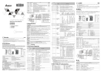
: Right limit input indicator ΦA : A-phase input of manual pulse generator Item LSN : Left limit input indicator ΦB : B-phase input of manual pulse generator : Zero signal input indicator CLR : Output clear signal Connect to DVP-PLC in series 3 Do NOT touch terminals when power on. Please turn off the power before wiring. DOG 3 This is an OPEN TYPE PLC. The PLC should be kept in an enclosure away from airborne dust, humidity, electric shock S/S risk and vibration. Also, it is equipped with protective methods such as some special tools or keys to open the enclosure, in CLR+, CLR- order to prevent hazard to users or damage the PLC. Output prior to power up. RP+, RP- X Introduction 1.1 1.3 Below 6.8 Power input specification #2 #1 H’4191 9 R/W 200KHz 200KHz VX.XX 01PU-H0T4320001 +24VDC IN DVP01PU-H Production No. Production week Production year (2004) Production plant (Taoyuan) START 24V STOP 0V +24V b1 b0 ASDA series 0 0 1 1 0 Motor 1 Machine 0 Combined 1 VDD 17 COM+ 11 LSN FP+ PLS 41 DOG FP- /PLS 43 S/S RP+ SIGN 37 RP- Manual pulse generator Shielded cable ΦA+ A-phase ΦA- Version No. Model name Product Profile and Outline (LED Indicator and Terminal Block) 24V /SIGN 36 CLR+ DI2 10 CLR- COM- 45 5-24VDC 5-24VDC 1 8 5 7 6 3 Unit: mm 1.DIN rail track (35mm) 2.Mounting wire to connect extension module/extension unit 3.Model name 4.Status Indicator (Power, Run and ERROR) 5.DIN rail clip 6.Terminal 7.Mounting hole 8.Terminal layout 9.Extension port to connect extension module/unit 10. RS-485 communication port POWER : Power indicator, +5V internal power START : Start input LV STOP : Stop input DOG ERROR : Error occurred indicator. It will blink when FP RP : DOG (near point signal) input 12 13 14 2.1 15 Function Specifications Item Power supply Max. number of connected axes Distance instruction Speed instruction External input : CW pulse output : CCW pulse output 9 Y Specifications External output LED Display CR#44 is not 0. PG0- 9 8 11 PG0+ 10 6 10 ΦB- 7 bit # 7 ΦB+ B-phase 3 #5 H’4195 9 R/W Delta Servo LSP 4 Setting Range System setting, Read-only (The model number of DVP-01PU is H’0110.) Range: 1 ~ +2,147,483,647 PPS/REV, factory setting: 2,000 Pulse/Revolution (PLS/REV) Range: 1 ~ +2,147,483,647 unit/REV, Factory setting: 1,000 (unit*1/REV) b15 b14 b13 b12 b11 b10 b9 b8 b7 Parameter setting Factory setting: H’0000 b6 b5 b4 b3 b2 b1 b0 Input/Output Circuit Bar code, serial No, firmware version Model type PU:Position control module input power is lower than 19.5V) #4 #3 H’4193 9 R/W Pulse required to rotate motor for 1 revolution (A) Machine travel range while motor rotate for 1 revolution (B) 3. Use copper conductors only, 60/75°C. Differential Line Driver For EH series MPU : Low voltage indicator (lit when external Model No. cable or conduit. 24Vdc 3W Output module specification Number of channels R 2. I/O signal wires or power supply should not run through the same multi-wire Below 6.8 Serial Number 2 #0 H’4190 9 130ms left. The torque of PLC terminal screw should be 5~8 kg-cm (4.3~6.9 in-lbs). To suit M3.5 screw terminals Delta PLC model name Model 1.2 - 1. Please wire I/O by O-type or Y-type terminals as the specification shown at Nameplate Model & Serial Number DVP series Content HW LW Address Wiring Model Explanation and Peripherals 01PU (position control unit) is mainly applied to the speed/position control of step/servo driven system. The maximum output pulse can be up to 200 KPPS, and built-in various route control modes. The DVP-PLC EH series can read/write 01PU via FROM/TO instrucitons. There are 54 CRs(Controlled Register) in 01PU and 16 bits for each register. The 32-bits data is composed of 2 continuous CR number. 1ms START response time 3 Do NOT connect the AC input power to any of the input/output terminals, or it may damage the PLC. Check all the wiring FP+, FP- DVP-01PU Position Control Unit CR No. 1ms Unit setting PG0+, PG0- Z Control Register 200KHz Position rate setting ΦB+, ΦB- Input All places between terminals and ground comply with the spec. START input polarity This Instruction Sheet only provides descriptions for installation, wiring and trial run. For further infromation, please refer to special module of PLC Application Manual. 200KHz Standard: IEC1131-2, IEC 68-2-6 (TEST Fc)/ IEC1131-2 & IEC 68-2-27 (TEST Ea) Pulse output format Position program & data transmission Description DC24V(-15% ~ +20%), Current consumption 140±30mA Power is supplied from EH series or external power supply. 8 units (axes); (All I/O points are not occupied. There are 8 special extension units at most to connect to EH series.) Distance value is set by CR. 1. Setting value: -2, 147,483,648~+2,147,483,647; 2. Selectable unit: um, mdeg, 10-4 inch, Pulse; 3. Selectable rate: 100, 101, 102, 103; 4. Selectable position: absolute and relative position instruction Speed value is set by CR. 1. Setting value: -2,147,483,648~+2,147,483,647 (conversion value of 10~200KPPS pulse); 2. Unit selectable: pulse/s, cm/min, 10deg/min, inch/min Photo coupler is for insulation and there are LED indications for all output/input signals. Outputs: FP and RP (line driver output 5V) Output: CLR is the type of NPN open collector transistor output (5~24VDC, less than 20mA) Photo coupler is for insulation and there are LED indications for all output/input signals. Input point: START, STOP, LSP, LSN, DOG(contact or open collector transistor, 24VDC± 10%, 5±1mA) Inputs:ΦA, ΦB(line driver or open collector transistor, 5~24VDC, 6~15mA) Input: PG0 (line driver or open collector transistor, 5~24VDC, 6~15mA) Three selectable modes: Pulse/Dir, FP(CW)/RP(CCW), A/B (all modes are line driver output) The DVP-PLC EH series can read/write data in CR via FROM/TO instrucitons. The 32-bits data is composed of 2 continuous CR number. The range of 16-bits CR is CR#0~CR#53. Unit Speed Position 3 ΦA+, ΦA- Vibration/Shock immunity Antistatic spec. 1. Operation: 0°C~55°C (Temperature), 50~95%(Humidity), pollution degree 2 2. Storage: -25°C~70°C (Temperature), 5~95%(Humidity) Pulse output format Warning 15ms/50ms 15ms 1ms Environmental specifications Operation/Storage LSP input polarity START STOP LSP / LSN - LSN input polarity Instruction Sheet Power input/DC24V (-15~+20%) Current consumption 100mA Start input terminal Stop input terminal Input right/left limit A-phase terminal (+, -) of manual pulse generator input (line driver input) B-phase terminal (+, -) of manual pulse generator input (line driver input) Zero signal input terminal +, - (line driver input) Offers two different functions depending on operation mode. (1) It is near-point signal in zero return mode. (2) It is start signal on interrupt 1st or interrupt 2nd speed mode. Signal common terminal of these Inputs (START, STOP, DOG, LSP, LSN) Clear signal (clear signal of internal error counter for Servo drive) FP/RP mode: CW pulse output I/O mode: Output pulse AB-phase mode: A-phase output FP/RP mode: CCW pulse output I/O mode: direction output AB-phase mode: B-phase output Other Specification Zero return direction +24V, 0V 2.2 Pulse direction Power supply Response character Explanation DOG trigger time Terminal name STOP input polarity Position Control Module Description DOG polarity Input/Output Terminal Acceleration curve options PG0 Description When DVP-01PU modules are connected to an MPU, the modules are numbered from 0 to 7. 0 is the closest and 7 is the farthest to the MPU. 8 modules is the max and they do not occupy any digital I/O points of the MPU. Attribute 5011627802-1PE2 http://www.delta.com.tw/industrialautomation/ LSP Latched 2006-12-08 Motor Combined Machine unit unit unit pulse um pulse m deg pulse 10-4inch pulse/sec cm/min pulse/sec 10deg/min pulse/sec inch/min b3 b2 0 0 1 1 0 1 0 1 Position rate setting 100 101 102 103 Pulse output format 0 FP + RP 1 Pulse + direction 0 A/B Phase pulse 1 b5 b4 0 0 1 1 Description When b[6]=0: positive logic, LSP input signal is ON, LPS signal is given. When b[6]=1: negative logic, LSP input signal is OFF, LPS signal is given. When b[7]=0: positive logic, LSN input signal is ON, LSN signal is given. When b[7]=1: negative logic, LSN input signal is OFF, LSN signal is given. When b[8]=0: zero return is executed to the direction of CP’s decreasing value. When b[8]=1, zero return is executed to the direction of CP’s increasing value. When CW running is executed: if b[9]=0, CP value is increasing. If b[9]=1, CP value is decreasing. When b[10]=0: DOG rising-edge is triggered. When b[10]=1,DOG falling-edge is triggered. (Interrupt 1st and interrupt 2nd speed position modes are enabled.) When b[11]=0: positive logic, DOG input signal is ON, DOG near point signal is given. When b[11]=1: negative logic, DOG input signal is OFF, DOG near point signal is given. When in zero return mode, interrupt 1st and interrupt 2nd speed position modes are enabled. When b[12]=0: trapezoid acceleration line is chosen. When b[12]=1, S acceleration line is chosen. When b[13]=0: 15ms; when b[13]=1: 50ms(for noise filter). When b[14]=0: positive logic, START input signal is ON, START input. When b[14]=1: negative logic, START input signal is OFF, START input. When b[15]=0: positive logic, STOP input signal is ON, STOP input. When b[15]=1: negative logic, STOP input signal is OFF, STOP input. #7 #6 H’4196 9 R/W Maximum speed Vmax #9 #8 H’4198 9 R/W Bias speed Vbias #11 #10 H’419A 9 R/W JOG speed VJOG #13 #12 H’419C 9 R/W Zero return speed VRT Zero return deceleration speed VCR The number of PG0 #16 H’41A0 9 R/W in zero return mode N The number of pulse #17 H’41A1 9 R/W in zero return mode P #15 #14 H’419E 9 R/W #18 H’41A2 9 R/W Zero return mode Range: 0 ~ +2,147,483,647 unit*1 (10 ~ 200K PPS) *2 Factory setting: 200,000 unit*1 Range: 0 ~ +2,147,483,647 unit*1 (0 ~ 200K PPS pulse transfer value) *2Factory setting: 0 unit*1 Range: 0 ~ +2,147,483,647 unit*1 (10 ~ 200K PPS pulse transfer value) *2Factory setting: 5,000 unit*1 Range: 0 ~ +2,147,483,647 unit*1 (10 ~ 200K PPS pulse transfer value) *2Factory setting: 50,000 unit*1 Range: 0 ~ +2,147,483,647 unit*1 (10 ~ 200K PPS pulse transfer value) *2, factory setting: 1,000 unit*1 Range: 0~+32,767 PLS, factory setting: 0 PLS Range: -32,768 ~+32,767 PLS, factory setting: 0 PLS b0: Zero return mode, b1: detect DOG falling-edge in zero return mode bit # Description 0 b[0]=0: normal mode, b[0]=1: override mode b[1]=0: DOG falling-edge detecting is on in zero return mode. b[1]=1: DOG falling-edge detecting is off in 1 zero return mode. When b[0]=1, Error reset. Error indicator is off and FLAG in CR (CR#43.b[5]) is cleared to 0. When b[1]=0→1 ,this is the same function as external input signal that forces to stop. When external signal that forces to stop is inputted or when b[1]=0→1, PU will decelerate to stop. When b[2]=1, CW running is forbidden, CW running instruction is disabled. When b[3]=1, CCW running is forbidden, CCW running instruction is disabled. When b[4]= 0→1, CW pulse is generated in JOG+ mode. When b[5]= 0→1, CCW pulse is generated in JOG- mode. When b[6]=0→1, zero return is performed. Zero return is performed differently by the different current position (CP) as the four following conditions: Position(1): Start position (as the right picture below [1] ) is at the right of zero point and DOG(near point signal), DOG=Off. Position(2): Start position (as the right picture below [2] ) is at the right of zero point, DOG=On. Position(3): Start position (as the right picture below [3] ) is at the left of zero point and DOG(near point signal), DOG=Off and LSN (hardware limit switch) signal=Off. Position(4): Start position (as the left picture below [4] ) is at the left of zero point and DOG(near point signal), DOG=Off and LSN (hardware limit switch) signal=On. 0→1 Tacc Tdec Vmax P(I) P(II) V(I) V(II) Vbias Time Tacc Tdec Vmax Vjog Vbias Time JOG 1 1 1 1 0→1 [4] [3] Zero point b3 b2 b1 b0 1st-speed position mode start b4 0/1 Interrupt 1st-speed position mode start b5 Vbias 0 Time Vbias Start 9~11 12 0/1 2nd-speed position mode start b6 Interrupt 2nd-speed position mode start Manual pulse generator range setting LSP/LSN stop mode MASK setting Return to factory setting - - ╳ - #32 H’41B0 b7 Variable speed operation mode start 0/1 0t1 0t1 Manual pulse generator input operation Timing STOP mode Description When b[7]=0, it is absolute position. When b[7]=1, it is relative position. When b[8]=0→1, start running by the work mode of CR#32. When b[10]=0→1, current position (CP) is cleared to 0. When b[12]=0, CLR outputs 130ms to Servo when zero return is completed. It is for the clear signal of servo internal error counter. When b[12]=1, CLR is common output point and the status(On/Off) is controlled by b[13]. When b[13]=0, CLR output point is Off. When b[13]=1, CLR output point is On. Work mode R/W factory setting: H’0001 V(I) 8 b15 b14 b13 b12 b11 b10 b9 b8 Tdec Vmax 7 [1] 7 8 10 V(I) P(I) Vbias Time Start DOG Tacc Speed Tdec 10 P(II) V(II) Time Start DOG Description Chart: (1)DOG rising-edge is triggered in normal mode. (2)DOG falling-edge detecting is On in zero return mode (CR#18_b1,0=00). (3)the number of PG0 in zero return mode N(CR#16). (4)the number of pulse in zero return mode P(CR#17). Speed(PPS) R/W #36 #35 H’41B3 ╳ R/W #38 #37 H’41B5 ╳ R/W #40 #39 H’41B7 ╳ R/W #41 H’41B9 9 R/W #42 H’41BA 9 R/W Current position CP(PLS) Current speed CS (PPS) Current position (unit*1) Current speed (unit*1) Communication address Baud Rate Setting The number of pulse in zero return mode (P) b8 b7 b6 b5 b4 b3 b2 b1 b0 Status indication CW pulse is outputting CCW pulse is outputting Zero return is done CP value overflow CR#46 Servo motor FP RP 3. When it arrives the (LSP/LSN) limit, output will stop immediately. When LSP is ON, CCW is allowed. When LSN is ON, CW is allowed. The position complete flag is not turned ON. 4. Position complete indication (CR#43, b6=Off). When position is done, the actual operation is expressed: (CR#43 b6=On). 5. The PU output pulse, pulse frequency of manual pulse generator, and the electronic gearing (CR#45, CR#46) are proportional to each other. Input frequency of The input frequency of manual pulse generator, factory setting: #48 #47 H’41BF ╳ R/W manual pulse 0 generator The count value of CW manual pulse input is “ +” symbol, on Accumulated pulse the contrary, the CCW manual pulse input is “-“symbol. And the #50 #49 H’41C1 ╳ R/W number of manual count value is nothing to do with the ratio setting of manual pulse generator electronic gearing (CR#45, #46). Factory setting: 0. #51 H’41C3 ╳ R/W Response speed of manual pulse generator Value Response speed 4ms (factory ≧5 setting) 4 32ms 3 108ms 2 256ms 1or 0 500ms ╳ R Terminal status #53 H’41C5 9 R System version System version: in hexadecimal system. Ex.: H’0100, the software version is V1.00. #52 H’41C4 Status When response speed setting is faster, the commands of pulse output and manual pulse generator input will be more synchronous. When response speed setting is slower, the command of pulse output is slower than the command of manual pulse generator input. Factory setting: 5 bit # b0 b1 b2 b3 b4 b5 b6 b7 b8 Description START input STOP input DOG input PG0 input LSP input LSN input A phase input B phase input CLR output When START input is On, b0 is On When STOP input is On, b1 is On When DOG input is On, b2 is On When PG0 input is On, b3 is On When LSP input is On, b4 is On When LSN input is On, b5 is On When A phase input is On, b6 is On When B phase input is On, b7 is On When CLR output is On, b8 is On *1: Unit setting is according to the varying of “ b0, b1” unit setting of CR#5. *2: Convert setting value to pulse unit: (1) output the maximum pulse if it exceeds the maximum range. (2) output the minimum pulse if it’s lower than the minimum range. [ Error Code & Troubleshooting It indicates 01PU hardware malfunction or error parameter setting when error LED flashes. ERR code is recorded in CR#44. Error code Error occurred flag Position completed indication - Route paused indication MPG input upward - Execution status factory setting: H’XXXX CR#45 = output pulse B phase The number of PG0 in zero return mode (N) MPG input downward R/W Input pulse X Zero return direction VCR VCR Please refer to “Error Code & Troubleshooting” for detail. Factory setting: H’0000 Servo drive A phase Contact DOG near signal Range display: -2,147,483,648~+2,147,483,647 PLS, factory setting: 0 PLS Range display: 0 ~ +2,147,483,647 PPS, factory setting: 0 PPS Range display: -2,147,483,648~+2,147,483,647 unit*1, factory setting: 0 unit*1 Range display: 0 ~ +2,147,483,647 unit*1, factory setting: 0 unit*1 RS-485 communication address, range: 01~255, factory setting: K1 Baud rate setting: 4800, 9600,19200bps, 38400 bps, 57600 bps, 115200 bps. ASCII mode data format is 7Bit, even bit and 1 stop bit (7 E 1). RTU mode data format is 8Bit, even bit and 1 stop bit (8, E, 1) b0: 4800 bps(bit/sec.), b1: 9600 bps(bit/sec.) (factory setting) b2: 19200 bps(bit/sec.), b3: 38400 bps(bit/sec.) b4: 57600 bps(bit/sec.), b5: 115200 bps(bit/sec.) b6~b14: reserved, b15: 0/1: RTU/ASCII mode(1: factory setting) - The content of this instruction sheet may be revised without prior notice. Please consult our distributors or download the most updated version at http://www.delta.com.tw/industrialautomation ╳ Error code ╳ Isolate from DOG near signal Description #43 H’41BB R VRT b15 b14 b13 b12 b11 b10 b9 When b[0] is triggered and START ON, it starts to execute 1st-speed position program. Step number and speed are decided by P(I)& V(I). When b[1] is triggered, START ON, and DOG external near point signal is performed, it starts to reload the value of the target position (I) P(I). ╳ Electronic gearing R/W numerator of MPG Please refer to the following description. Factory setting: H’1 input Electronic gearing #46 H’41BE ╳ R/W Please refer to the following description. Factory setting: H’1 denominator of MPG input z Input operation of manual pulse generator: 1. Manual pulse generator input operation is ON when b5 of CR#32 is set to 1. 2. 2-phase(A phase/B phase) can be input from the manual pulse generator to ΦA and ΦB. FP/RP I/O pulse is as follows: #45 H’41BD Vbias DOG falling-edge detecting ╳ When b[10]=1, it means manual pulse generator inputs with counting downward. #44 H’41BC V(I) When b[5]= 0→1, manual pulse generator input is started. Please refer to the setting of CR#45~#51. When b[5]=1Æ0, manual pulse generator input is stopped. Also, b[5] can start running by activating START command. b[6]=0: When STOP is input, motor will decelerate to stop under running mode. When rerun instruction is received, the distance that uncompleted will be neglected and motor will go to execute the next position instruction immediately. b[6]=1: When STOP is input, motor will decelerate to stop under running mode. When rerun instruction is received, the distance that uncompleted will be done and then motor will go to execute the next position instruction. b[7]=0: The output pulse of manual pulse generator is unlimited. b[7]=1: The output pulse of manual pulse generator is limited between P(I) and P(II). When the output pulse is out of the range, it will be decelerated and then stopped outputting. b[8]=0: When motor is running, it will decelerate to stop if LSP/LSN signal is received. b[8]=1: When motor is running, it will stop immediately if LSP/LSN signal is received. MASK setting (1st-speed operation, 2nd-speed operation, interrupt 1st-speed operation, interrupt 2nd-speed operation) b[11~9]=K0(000) or other value: NO MASK function. b[11~9]=K1(001) : the rising-edge of input terminal ΦA± will trigger MASK. b[11~9]=K2(010) : the falling-edge of input terminal ΦA± will trigger MASK. b[11~9]=K3(011) : the rising-edge of input terminal ΦB± will trigger MASK. b[11~9]=K4(100) : the falling-edge of input terminal ΦB± will trigger MASK. b[12]=1: All parameters return to factory setting. #34 #33 H’41B1 bit # Description 0 When b[0]=0, system is ready. When b[0]=1, PU is executing position control mode (Pulse is outputting). 1 When b[1]=1, CW pulse is outputting. 2 When b[2]=1, CCW pulse is outputting. When b[3]=1, zero return is completed. b[3] is cleared to 0 by user program. When PU is power on again, 3 b[3] will be cleared to 0 automatically. When b[4]=1, “Current position CP(PLS)”(CR#34, #33), that is 32 bit, is overflow. When PU is power on 4 again or complete zero return, b[4] will be cleared to 0 automatically. 5 When b[5]=1, PU error occurred. Error code is stored in CR#44. When PU starts to execute zero return or error reset (only when error occurred), it will clear b[6] to 0. When 6 zero return or position control is completed, it will set b[6] to 1. When PU is running, STOP status is on. PU will stop output, and b[7] will be set to 1 at this time. It means 7 that PU is pause and it will execute the uncompleted route and b[7] will be cleared to 0 after STOP status is off. 9 When b[9]=1, it means manual pulse generator inputs with counting upward. Vmax DOG - 13 Tacc Speed 6 bit # 12 4 5 LSP [2] Vmax When b[4] is triggered, it starts to execute variable speed operation and PU starts to send pulse as well. The pulse direction is set by the sign bit of V(I) value. Zero point return direction DOG Tdec Stop Hardware polarity switch LSN Interrupt 2nd -speed position operation mode Speed - JOG operation mode Speed 0→1 Tacc Speed When b[2] is triggered and START ON, it starts to execute 1st-speed position operation and then the 2nd-speed position operation will be started immediately after 1st-speed operation is completed. When b[3] is triggered and START ON, if the DOG external near point signal is executed during 1st-speed position operation, the 2nd-speed position operation will be started immediately. 2 2nd -speed position operation mode Error reset Software STOP CW pulse STOP CCW pulse STOP JOG+ JOG- Zero return start ABS/REL Coordinate Software START Timing Interrupt 1st -speed position operation mode Time - 6 1 P(I) Vbias Variable speed operation mode 2 3 4 5 Description Zero return operation route 1 0 V(I) Start bit # 0 bit # Vmax 3 - Current position = 0 (CP=0) CLR signal output mode - CLR output (On/Off) Running instruction factory setting: H’0000 - R/W - ╳ Tdec Start b15 b14 b13 b12 b11 b10 b9 b8 b7 b6 b5 b4 b3 b2 b1 b0 #31 H’41AF Tacc 1st-speed position operation mode Speed Zero return operation mode #20 #19 H’41A3 9 R/W Zero point setting (HP) Range: 0 ~ ±999,999 unit*1, factory setting: 0 unit*1 #21 H’41A5 9 R/W Acceleration time Tacc Range: 10 ~ +32,767 ms, factory setting: 100 ms #22 H’41A6 9 R/W Deceleration time Tdec Range: 10 ~ +32,767 ms, factory setting: 100 ms Range: -2,147,483,648 ~ +2,147,483,647 unit*1 #24 #23 H’41A7 ╳ R/W Target position (I) P(I) (-2,147,483,648 ~ +2,147,483,647 pulse transfer value) *2, factory setting: 0 unit*1 Range: -2,147,483,648 ~ +2,147,483,647 unit*1 (10 ~ 200K #26 #25 H’41A9 ╳ R/W Running speed (I) V(I) PPS pulse transfer value) *2, factory setting: 1,000 unit*1 Range: -2,147,483,648 ~ +2,147,483,647 unit*1 #28 #27 H’41AB ╳ R/W Target position (II)P(II) (-2,147,483,648 ~ +2,147,483,647 pulse transfer value) *2, factory setting: 0 unit*1 Running speed (II) Range: 0 ~ +2,147,483,647 unit*1 (10 ~ 200K PPS pulse #30 #29 H’41AD ╳ R/W V(II) transfer value) *2, factory setting: 2,000 unit*1 Error code Description H’0000 No error Description H’0013 Zero return deceleration (VRT) setting error H’0001 H’0002 H’0010 Target address (I) setting error Target address (II) setting error Running speed (I) setting error H’0014 H’0020 H’0021 JOG speed (VJOG) setting error CW pulse is forbidden CCW pulse is forbidden H’0011 H’0012 Running speed (II) setting error Zero return deceleration (VCR) setting error H’0080 H’0081 Hardware error in internal memory Data write in error in internal memory