1
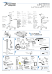
About Cautions
Replacing the Riser Card
CAUTION: Only trained service technicians are authorized to remove the system cover and access any
of the components inside the system. See your Product Information Guide for complete information
about safety precautions, working inside the computer, and protecting against electrostatic discharge.
This document provides instructions about upgrading the riser card in your system.
NOTE: See your Installation and Troubleshooting Guide for detailed instructions on removing or
replacing components.
Removing the Riser Card
1
Open the system.
2
Remove any expansion card(s).
3
Lift the two plastic rivets that secure the riser card insulator, then remove the insulator.
See Figure 1-1.
4
If a SCSI data cable is connected to the riser card, disconnect the SCSI data cable from
the SCSI data connector on the riser card. See Figure 1-1.
5
Raise the riser card cam lever, then lift the riser card from the chassis. See Figure 1-1.
Replacing the Riser Card
1
Ensure that the riser card cam lever is in the vertical position. See Figure 1-1.
2
Lower the new riser card into position.
Ensure that the cam lever fits through the opening near the outer edge of the riser card and
the connector on the underside of the riser card aligns with the corresponding connector on
the system board.
3
If you disconnected the SCSI data cable while removing the riser card, reconnect the cable to
the new riser card.
4
When you are certain the riser card is correctly aligned with the system board, carefully close
the cam lever to lock the riser card into place.
5
Place the plastic riser card insulator over the riser card and press down on the two plastic rivets
to secure the insulator.
July 2004
www.dell.com | support.dell.com
CAUTION: A CAUTION indicates a potential for property damage, personal injury, or death.
www.dell.com | support.dell.com
6
Reinstall any expansion card(s).
7
Close the system.
Figure 1-1.
Installing and Removing the Riser Card
plastic rivet
riser card insulator
plastic rivet
riser card
SCSI data connector
cam lever
____________________
Information in this document is subject to change without notice.
© 2004 Dell Inc. All rights reserved. Printed in the U.S.A.
Reproduction in any manner whatsoever without the written permission of Dell Inc. is strictly forbidden.
Trademarks used in this text: Dell and the DELL logo are trademarks of Dell Inc.
Other trademarks and trade names may be used in this document to refer to either the entities claiming the marks and names
or their products. Dell Inc. disclaims any proprietary interest in trademarks and trade names other than its own.
关于警告
更换提升卡
警告:只有经过培训的维修技术人员才能卸下主机盖并拆装系统内部的任何组件。有关安全预
防措施、拆装计算机内部组件以及防止静电释放的完整信息,请参阅 《产品信息指南》。
本说明文件提供了有关在系统中升级提升卡的说明。
注:有关安装和更换组件的详情,请参阅 《安装与故障排除指南》。
卸下提升卡
1
打开系统外壳。
2
卸下扩充卡。
3
提起两颗固定提升卡绝缘体的塑料铆钉,然后卸下绝缘体。请参阅图 1-1。
4
如果有一根 SCSI 数据电缆连接到提升卡上,则将此 SCSI 数据电缆与提升卡上的 SCSI
数据连接器断开。请参阅图 1-1。
5
提起提升卡凸轮拉杆,然后将提升卡从机箱中提起。请参阅图 1-1。
更换提升卡
1
确保提升卡凸轮拉杆处于垂直位置。请参阅图 1-1。
2
将新提升卡向下压入到位。
确保凸轮拉杆能通过提升卡外缘附近的开口,而且提升卡下侧连接器与系统板上相应的
连接器对准。
3
如果卸下提升卡时断开了 SCSI 数据电缆,则请将电缆重新连接到新提升卡上。
4
确保提升卡与系统板正确对准后,小心合上凸轮拉杆,将提升卡锁定到位。
5
将塑料提升卡绝缘体放在提升卡上,按下两个塑料铆钉,固定好绝缘体。
6
重新安装扩充卡。
7
合上系统外壳。
2004 年 7 月
www.dell.com | support.dell.com
警告:警告表示存在可能导致财产损失、人身伤害或死亡的潜在危险。
www.dell.com | support.dell.com
图 1-1.
装卸提升卡
塑料铆钉
提升卡绝缘体
塑料铆钉
提升卡
SCSI 数据连接器
凸轮拉杆
____________________
本文中的信息如有更改,恕不另行通知。
© 2004 Dell Inc.。保留所有权利。美国印制。
未经 Dell Inc. 书面许可,不得以任何方式进行复制。
本文件中使用的商标:Dell 和 DELL 徽标是 Dell Inc. 的商标。
本文件中述及的其它商标和产品名称是指拥有相应商标和名称的公司或其制造的产品。
Dell Inc. 对本公司的商标和产品名称之外的其它商标和产品名称不拥有任何专有权。
À propos de la mention “Précaution”
Remplacement de la carte de montage
PRÉCAUTION : seuls les techniciens de maintenance qualifiés sont habilités à retirer le capot du
système et à accéder aux composants du système. Consultez le Guide d'information sur le produit pour
obtenir des informations détaillées sur les consignes de sécurité, les interventions dans l'ordinateur
et la protection contre les décharges électrostatiques.
Ce document contient des informations concernant la mise à niveau de la carte de montage
du système.
REMARQUE : consultez le Guide d'installation et de dépannage pour obtenir des instructions détaillées
sur le retrait ou le remplacement de composants.
Retrait de la carte de montage
1
Ouvrez le système.
2
Retirez toutes les cartes d'extension.
3
Soulevez les deux rivets de plastique qui maintiennent l'isolant de la carte de montage,
puis retirez l'isolant. Voir la figure 1-1.
4
Si un câble de données SCSI est connecté à la carte de montage, déconnectez-le.
Voir la figure 1-1.
5
Ouvrez le levier de maintien de la carte de montage, puis soulevez celle-ci pour la retirer
du châssis. Voir la figure 1-1.
Remplacement de la carte de montage
1
Vérifiez que le levier de la carte est en position verticale. Voir la figure 1-1.
2
Abaissez la nouvelle carte de montage pour la placer correctement.
Vérifiez que le levier peut s'emboîter dans l'ouverture située près du bord extérieur de la carte
de montage, et que le connecteur situé sous cette dernière s'aligne avec le connecteur
correspondant de la carte système.
3
Si vous avez déconnecté le câble de données SCSI lors du retrait de la carte de montage,
reconnectez-le sur la nouvelle carte.
4
Lorsque l'alignement est correct, abaissez le levier avec précaution pour verrouiller la carte.
5
Placez l'isolant de la carte de montage au-dessus de cette dernière. Appuyez ensuite sur
les deux rivets en plastique pour les emboîter.
Juillet 2004
www.dell.com | support.dell.com
PRÉCAUTION : une PRÉCAUTION indique un risque potentiel d'endommagement du matériel,
de blessure corporelle ou de mort.
www.dell.com | support.dell.com
6
Réinstallez toutes les cartes d'extension.
7
Refermez le système.
Figure 1-1.
Installation et retrait de la carte de montage
Rivet de plastique
Isolant de la carte de montage
Rivet de plastique
Carte de montage
Connecteur du câble
de données SCSI
Levier
____________________
Les informations contenues dans ce document peuvent être modifiées sans préavis.
© 2004 Dell Inc. Tous droits réservés. Imprimé aux États-Unis.
La reproduction de ce document de quelque manière que ce soit sans l'autorisation écrite de Dell Inc. est strictement interdite.
Marques utilisées dans ce document : Dell et le logo DELL sont des marques de Dell Inc.
Tous les autres noms de marques et marques commerciales utilisés dans ce document se rapportent aux sociétés propriétaires
des marques et des noms de ces produits. Dell Inc. décline tout intérêt dans l'utilisation des marques déposées et des noms de
marques ne lui appartenant pas.
Warnhinweise
Riser-Karte austauschen
VORSICHT: Nur ausgebildete Servicetechniker sind befugt, die Systemabdeckung zu entfernen
und Komponenten im Innern des Systems zu handhaben. Ausführliche Informationen zu den
Sicherheitsvorkehrungen beim Arbeiten im Innern des Computers und zum Schutz vor elektrischer
Entladung finden Sie im Produktinformationshandbuch.
Dieses Dokument enthält eine Anleitung zum Austausch der Riser-Karte in Ihrem System.
ANMERKUNG: Ausführliche Erläuterungen zum Einbau oder Austausch von Komponenten finden Sie
im Installations- und Fehlerbehebungshandbuch.
Riser-Karte entfernen
1
Öffnen Sie das System.
2
Entfernen Sie die/alle Erweiterungskarte(n).
3
Ziehen Sie die beiden Plastik-Stecker ab, mit der die Isolierung der Riser-Karte befestigt ist,
und entfernen Sie anschließend die Isolierung aus dem Gehäuse. Siehe Abbildung 1-1.
4
Wenn ein SCSI-Kabel an die Riser-Karte angeschlossen ist, ziehen Sie es aus dem Anschluss
auf der Riser-Karte. Siehe Abbildung 1-1.
5
Bringen Sie den Verriegelungshebel für die Riser-Karte in die vertikale Position, und heben
Sie die Karte aus dem Gehäuse. Siehe Abbildung 1-1.
Riser-Karte austauschen
1
Vergewissern Sie sich, dass sich der Verriegelungshebel für die Riser-Karte in vertikaler
Position befindet. Siehe Abbildung 1-1.
2
Senken Sie die neue Riser-Karte in die richtige Position ab.
Vergewissern Sie sich, dass der Verriegelungshebel durch die Öffnung am Rand der RiserKarte passt und der Stecker an der Unterseite der Riser-Karte am passenden Anschluss
auf der Systemplatine ausgerichtet ist.
3
Falls Sie das SCSI-Kabel von der Riser-Karte getrennt haben, schließen Sie es jetzt an
die neue Riser-Karte an.
4
Wenn Sie sicher sind, dass die Riser-Karte richtig ausgerichtet ist, schließen Sie vorsichtig
den Verriegelungshebel.
Juli 2004
www.dell.com | support.dell.com
VORSICHT: VORSICHT zeigt eine mögliche gefährliche Situation an, die bei Nichtbeachtung
zu Sachschäden, Körperverletzungen oder zum Tod führen könnte.
www.dell.com | support.dell.com
5
Legen Sie die Isolierung auf die Riser-Karte, und drücken Sie auf die zwei Plastik-Stecker,
um die Isolierung zu befestigen.
6
Installieren Sie die/alle Erweiterungskarte(n) neu.
7
Schließen Sie das System.
Abbildung 1-1. Riser-Karte installieren und entfernen
Plastik-Stecker
Isolierung der Riser-Karte
Plastik-Stecker
Riser-Karte
SCSI-Anschluss
Verriegelungshebel
____________________
Irrtümer und technische Änderungen vorbehalten.
© 2004 Dell Inc. Alle Rechte vorbehalten. Gedruckt in den USA.
Eine Reproduktion dieses Dokuments in jeglicher Form ohne schriftliche Genehmigung von Dell Inc. ist streng verboten.
Marken in diesem Text: Dell und das DELL-Logo sind Marken der Dell Inc.
Andere in diesem Dokument möglicherweise verwendete Marken und Handelsbezeichnungen sind unter Umständen Marken
und Namen der entsprechenden Firmen oder ihrer Produkte. Dell Inc. erhebt keinen Anspruch auf Marken und
Handelsbezeichnungen mit Ausnahme der eigenen.
警告について
ライザカードの取り付け
警告:システムのカバーを取り外して、システム内部に手を触れる作業は、トレーニングを
受けたサービス技術者の方だけが行ってください。安全上の注意、コンピュータ内部の作業、
および静電気障害への対処の詳細については、『製品情報ガイド』を参照してください。
本書では、お使いのシステムのライザカードをアップグレードする手順を説明します。
メモ:コンポーネントの取り外しや交換の詳しい手順については、『インストール & トラブ
ルシューティングガイド』を参照してください。
ライザカードの取り外し
1
システムカバーを開きます。
2
拡張カードを取り外します。
3
ライザカードの絶縁カバーを固定している 2 本のプラスチック製リベットを抜き取っ
て、絶縁カバーを取り外します。図 1-1 を参照してください。
4
SCSI データケーブルがライザカードに接続している場合は、ライザカードの SCSI デー
タコネクタからこのケーブルを抜き取ります。図 1-1 を参照してください。
5
ライザカードのカムレバーを起こし、ライザカードをシャーシから持ち上げます。
図 1-1 を参照してください。
ライザカードの取り付け
1
ライザカードのカムレバーが垂直位置になっていることを確認します。
図 1-1 を参照してください。
2
新しいライザカードを所定の位置まで下ろします。
カムレバーがライザカードの外縁近くにある開口部を貫通していて、ライザカード下
面のコネクタとシステム基板上の対応するコネクタの位置が合っていることを確認し
ます。
3
ライザカードの取り外し時に SCSI データケーブルを抜き取った場合は、このケーブル
を新しいライザカードに接続します。
4
ライザカードのシステム基板に対する位置が正しいことを確認したうえで、慎重にカ
ムレバーを閉じ、ライザカードを所定の位置に固定します。
2004 年 7 月
www.dell.com | support.dell.com
警告:警告は、物的損害、けが、または死亡の原因となる可能性があることを示します。
www.dell.com | support.dell.com
5
ライザカードにプラスチック製の絶縁カバーをかぶせ、2 本のプラスチック製リベッ
トを対応する穴に差し込んで絶縁カバーを固定します。
6
拡張カードを元のように取り付けます。
7
システムカバーを閉じます。
図 1-1
ライザカードの取り付けと取り外し
プラスチック製リベット
ライザカード絶縁カバー
プラスチック製リベット
ライザカード
SCSI データコネクタ
カムレバー
____________________
ここに記載されている内容は予告なく変更されることがあります。
© 2004 すべての著作権は Dell Inc. にあります。Printed in the U.S.A.
Dell Inc. の書面による許可のない複製は、いかなる形態においても厳重に禁じられています。
本書で使用されている商標について:Dell および DELL ロゴは Dell Inc. の商標です。
本書では、必要に応じて上記以外の商標および会社名が使用されている場合がありますが、
これらの商標や会社名は、一切 Dell Inc. に所属するものではありません。
주의에 대하여
라이저 카드 교체
주의 : 숙련된 서비스 기술자만 시스템 덮개를 분리하고 시스템 내부의 구성요소에 액세스해야
합니다 . 안전 지침 , 컴퓨터 내부 작업 및 정전기 방전 보호에 대한 자세한 내용은 시스템 정보 설
명서를 참조하십시오 .
본 설명서에서는 시스템에 라이저 카드를 업그레이드하는 지침을 제공합니다.
참고: 구성 요소 제거 및 교체에 대한 세부 지침은 설치 및 문제 해결 설명서 를 참조하십시오.
라이저 카드 분리
1
시스템을 여십시오.
2
확장 카드를 분리하십시오.
3
라이저 카드 절연체를 보호하는 두 플라스틱 고정 못을 들어올리고 절연체를 분리합니다.
그림 1-1을 참조하십시오.
4
SCSI 데이터 케이블이 라이저 카드에 연결되어있다면 라이저 카드의 SCSI 데이터 커넥
터로부터 SCSI 데이터 케이블의 연결을 끊습니다. 그림 1-1을 참조하십시오.
5
라이저 카드 캠 레버를 들어올린 다음 섀시로부터 라이저 카드를 들어올립니다.
그림 1-1을 참조하십시오.
라이저 카드 교체
1
라이저 카드 캠 레버가 수직 위치에 있는지 확인하십시오. 그림 1-1을 참조하십시오.
2
새 라이저 카드를 제자리로 내려 놓으십시오.
캠 레버가 라이저 카드의 바깥 에지에 맞는지 및 라이저 카드의 하단에 있는 커넥터가 시
스템 보드의 상응하는 커넥터와 맞는지를 확인하십시오.
3
라이저 카드를 분리하는 동안 SCSI 데이터 케이블의 연결을 끊었다면 새 라이저 카드에
연결하십시오.
4
라이저 카드가 시스템 보드와 확실히 맞는 것을 확인한 후 조심스럽게 캠 레버를 닫아서
라이저 카드가 제 위치에 들어가 앉도록 합니다.
5
플라스틱 라이저 카드 절연체를 라이저 카드 위에 덮고 두 플라스틱 고정 못을 눌러 끼워
서 절연체를 보호합니다.
6
확장 카드를 재설치하십시오.
7
시스템 덮개를 닫으십시오.
2004 년 7 월
www.dell.com | support.dell.com
주의 : 주의는 위험한 상황 , 심각한 부상 또는 사망할 우려가 있음을 알려줍니다 .
www.dell.com | support.dell.com
그림 1-1.
라이저 카드 설치 및 분리
플라스틱 고정 못
라이저 카드 절연체
플라스틱 고정 못
라이저 카드
SCSI 데이터 커넥터
캠 레버
____________________
본 설명서에 수록된 정보는 사전 통보 없이 변경될 수 있습니다.
© 2004 Dell Inc. All rights reserved. 미국에서 인쇄.
Dell Inc.의 사전 승인 없이 어떠한 경우에도 무단 복제하는 것을 엄격히 금합니다.
본 설명서에 사용된 상표: Dell 및 DELL 로고 는 Dell Inc.의 등록 상표입니다.
본 설명서에서 특정 회사의 표시나 제품 이름을 지칭하기 위해 기타 상표나 상호를 사용할 수도 있습니다.
Dell Inc.은 자사가 소유하고 있는 것 이외에 기타 모든 등록 상표 및 상표 이름에 대한 어떠한 소유권도 없습니다.
Información sobre los avisos de precaución
Sustitución de la tarjeta vertical
PRECAUCIÓN: los técnicos de servicio especializados son las únicas personas autorizadas
para retirar las cubiertas y acceder a los componentes internos del sistema. Consulte la Guía de
información del producto para obtener información completa sobre las precauciones de seguridad,
la manipulación de las piezas internas del ordenador y la protección contra descargas electrostáticas.
En este documento se facilitan instrucciones para actualizar la tarjeta vertical del sistema.
NOTA: consulte la Guía de instalación y solución de problemas para obtener instrucciones detalladas
sobre la extracción y la colocación de componentes.
Extracción de la tarjeta vertical
1
Abra el sistema.
2
Extraiga las tarjetas de expansión.
3
Levante los dos remaches de plástico que fijan el aislante de la tarjeta vertical
y, a continuación, extraiga el aislante. Consulte la figura 1-1.
4
Si un cable de datos SCSI está conectado a la tarjeta vertical, desconéctelo del conector
correspondiente de la tarjeta vertical. Consulte la figura 1-1.
5
Levante la palanca de fijación de la tarjeta vertical y, a continuación, extraiga la tarjeta
del chasis. Consulte la figura 1-1.
Sustitución de la tarjeta vertical
1
Asegúrese de que la palanca de fijación de la tarjeta vertical esté en posición vertical.
Consulte la figura 1-1.
2
Baje la nueva tarjeta y colóquela en la posición adecuada
Asegúrese de que la palanca de fijación pase a través de la abertura situada cerca del borde
exterior de la tarjeta vertical y de que el conector de la parte inferior de la tarjeta vertical
quede alineado con el conector correspondiente de la placa base.
3
Si ha desconectado el cable de datos SCSI al extraer la tarjeta vertical, vuelva a conectarlo
a la nueva tarjeta vertical.
4
Cuando esté seguro de que la tarjeta vertical está bien alineada con la placa base,
cierre cuidadosamente la palanca de fijación para fijar la tarjeta.
Julio de 2004
www.dell.com | support.dell.com
PRECAUCIÓN: un mensaje de PRECAUCIÓN indica el riesgo de daños materiales, lesiones corporales
o incluso la muerte.
www.dell.com | support.dell.com
5
Coloque el aislante de plástico de la tarjeta vertical sobre la tarjeta vertical y presione
los remaches de plástico hacia abajo para fijar el aislante.
6
Reinstale las tarjetas de expansión.
7
Cierre el sistema.
Figura 1-1.
Instalación y extracción de la tarjeta vertical
Remache de plástico
Aislante de la tarjeta vertical
Remache de plástico
Tarjeta vertical
Conector de datos SCSI
Palanca de fijación
____________________
La información contenida en este documento puede modificarse sin previo aviso.
© 2004 Dell Inc. Reservados todos los derechos. Impreso en EE. UU.
Queda estrictamente prohibida la reproducción de este documento en cualquier forma sin la autorización por escrito de Dell Inc.
Marcas comerciales que aparecen en el texto: Dell y el logotipo de DELL son marcas comerciales de Dell Inc.
Otras marcas y otros nombres comerciales pueden utilizarse en este documento para hacer referencia a las entidades que los poseen
o a sus productos. Dell Inc. renuncia a cualquier interés sobre la propiedad de marcas y nombres comerciales que no sean los suyos.