1
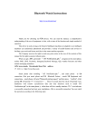
System Series
Operating Instructions
© 2000 Crystal Audio
Table of contents
Information about this manual……………………………………
2
Connecting the speakers……..………………………………….
3
Positioning the speakers………………………………………….
4
Adjusting your amplifier for the System Series Speakers……..
5
Precautions…………………………………………………………
5
Specifications………………………………………………………
6
Information about this manual
This instruction manual is referred to the following speaker models:
System 2
System 4
System Dipole 4
System Center 4
System 5
System 6
System Center 6
SystemBass twin 7
System 8
SystemBass 10
SystemBass 12R
Please read this instruction manual before using the System Series Speakers.
2
Connecting the speakers
This section explains how to conect your speakers to your amplifier.
•
•
•
•
•
•
Before connecting the speakers make sure that your amplifier is turned off.
Turn off the subwoofer before connecting the input signal cable on its internal
amplifier.
Connect the plus (+) and minus (-) terminals of each speaker to the corresponding
plus (+) and minus (-) terminals on the amplifier.
If a biwire type of connection is used (except System 2, System 5 and System
Dipole 4 that have single wire binding posts), the gold plated bridges must be taken
off. Unscrew the binding post’s screws and pull off the two bridges. Tighten the
screws.
If you use bare speaker wire at the speaker terminals, remove the binding post’s
screw and place the bare wire into the side opening of the terminal. Then tighten the
screw.
If a banana plug type is used, just push the plug into the binding post’s top hole.
Figure 1 shows a typical system connection of two front speakers, two rear speakers,
one center speaker and one subwoofer on a AV amplifier for 5.1 channel reproduction.
Front Right
Front Left
Center
AV Amplifier
Subwoofer
Center
Front R
L
Rear R
L
LINE IN
Rear Left
Rear Right
Subwoofer
Figure 1. Typical connection of 5.1 channel configuration.
3
Positioning the speakers
•
Each speaker must have approximately the same distance from the listening
position in order to have a better stereo sound image.
•
The front speakers must be placed on an imaginary arc that includes the position of
the center speaker. Thus, the front speakers and the center speaker will have the
same distance from the listening position.
•
The center speaker must be placed on top or beneath of the television. If you place it
beneath the television, you must give it an angle in order to face the listeners.
•
The tweeters of the front and center speakers must be at the same height with a
sitting listener’s ear. If needed, bases can be used.
•
The rear speakers should be dipoles and are best located to the side of or behind
the listening position, at least 0.6m (2 feet) above the listening position.
•
The subwoofer must be placed as close as possible to the listening position, e.g.
beside or at the back of the couch.
Note
Carpets, curtains and furniture improve sound quality in the listening room, since they
reduce reflections of sound.
Figure 2 shows a typical placement of the speakers in the music-home theater room.
Front Left
Front Right
Center
45o - 60o
Rear Left
Rear Right
Subwoofer
Figure 2.
4
Adjusting your amplifier for the System Series
All System Series Speakers are designed for use with subwoofer. The adjustments that
must be made on the setup menu of your AV amplifier are:
Speaker
Menu on AV amplifier about the size of the speaker
Front
SMALL
Rear
SMALL
Center
SMALL
Also you must adjust the amplifier so that it recognizes that a subwoofer is present
(Subwoofer YES or ON).
These adjustments are very important for the protection of your speakers.
Precautions
•
The AV amplifier you use must be set to SMALL position for all the System Series
Speakers (front, rear & center).
•
Before operating a subwoofer, make sure that the operating voltage of the local
power supply and the subwoofer are identical.
•
Before connecting the speakers make sure that your amplifier is turned off.
•
Turn off the subwoofer before connecting the input signal cable on its internal
amplifier.
•
Make sure that you have connected the plus (+) and minus (-) terminals of each
speaker to the corresponding plus (+) and minus (-) terminals on the amplifier.
•
Make sure that all screws on the binding posts are tight enough, especially if you are
using bare speaker wires. A contact between bare speaker wires may cause shortcircuit which can damage your equipment.
•
Avoid the use of Treble - Bass adjustments and Loudness especially at high level
output. Also avoid the use of equalizers. In this way you protect your speakers and
you get better sound with less distortion.
•
The possibility of damaging your speakers is greater if you use low power amplifiers
that operate at their limits especially with the Treble – Bass adjustments at their
maximum value.
Such amplifiers clip very easily, which can destroy your speakers. Tweeters are
more vulnerable on this kind of use.
Therefore, high power amplifiers are more preferable.
Do not drive each speaker with a continuous wattage exceeding the maximum
power indicated on this instruction manual for the specified speaker.
•
5
•
Use the best speaker and interconnect cables you can afford.
•
Do not place the speakers in dusty, humid environment.
•
Avoid exposure to direct sunlight.
Specifications
Model
System 2
System 4
System 6
System 8
2 way
2 way
3 way
3 way
Magnetically shielded
v
v
v
v
Woofer 3” aluminum concave
2
4
6
8
Tweeter 1” aluminum dome
-
1
1
1
Tweeter 1” neodymium magnet,
ceramic dome
1
-
-
-
Impedance
8
8
6
4
120-25
110-25
100-25
90-25
Nominal input power in SMALL mode
(Watt RMS)
80
100
125
150
Maximum input power (Watt)
160
200
250
300
Sensitivity (dB/2.83V/1m)
91
92
92
92
Enclosure Type :Bass reflex
v
v
v
v
Single Wire Binding Post Gold Plated
v
-
-
-
Biwire Binding Post Gold Plated
-
v
v
v
110x270x80
110x1090x80
110x1210x80
110x1310x105
System 5
2 way
System
Dipole 4
2 way
System
Center 4
2 way
System
Center 6
3 way
Magnetically shielded
v
v
v
v
Woofer 3” aluminum concave
8
4
4
6
Tweeter 1” aluminum dome
1
2
1
-
Tweeter 1” neodymium magnet,
ceramic dome
-
-
Impedance
4
8
8
6
90-25
110-25
110-25
100-25
Nominal input power in SMALL mode
(Watt RMS)
150
100
Maximum input power (Watt)
300
200
200
250
Sensitivity (dB/2.83V/1m)
92
92
92
92
v
v
v
v
Speaker
Frequency Response (Hz – kHz)
Dimensions (WxHxD) mm
Model
Speaker
Frequency Response (Hz – kHz)
Enclosure Type :Bass reflex
-
100
1
125
6
Single Wire Binding Post Gold Plated
v
v
-
-
Biwire Binding Post Gold Plated
-
-
v
v
110x270x110 s
220x160x110 c
240x300x120
500x110x80
585x160x108
Dimensions (WxHxD) mm
Model
SystemBass twin 7
SystemBass 10
SystemBass 12R
v
v
v
2x7”
10”
12”
4
4
4
24-160
20-160
19-160
Nominal input power in SMALL mode
(Watt RMS)
90
170
200
Sensitivity (dB/2.83V/1m)
92
93
94
Remote controlled, Volune &
Frequency control on remote
-
-
v
Enclosure Type :Bass reflex
v
v
v
Auto Power ON/OFF
v
v
v
210x375x420
340x505x435
340x505x455
Active subwoofer
Woofer
Impedance
Frequency Response (Hz)
Dimensions (WxHxD) mm
For System 5 in dimensions box are s stands for satellites and c stands for center.
Specifications are subject to change without notice.
7