1
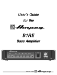
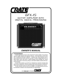
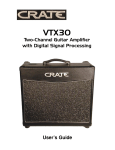
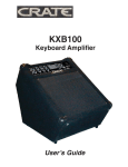
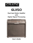
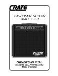
GT3500H
Three-Channel
Guitar Amplifier
User’s Guide
TABLE OF CONTENTS:
Introduction . . . . . . . . . . . . . . . . . . . . . . . . . . . . . . . . . .3
The Front Panel . . . . . . . . . . . . . . . . . . . . . . . . . . . . . . .4
The Rear Panel . . . . . . . . . . . . . . . . . . . . . . . . . . . . . . .5
Suggested Settings . . . . . . . . . . . . . . . . . . . . . . . . . . . .6
System Block Diagram . . . . . . . . . . . . . . . . . . . . . . . . .7
Technical Specifications . . . . . . . . . . . . . . . . .back cover
CAUTION
PRECAUCION
ATTENTION
RISK OF ELECTRIC SHOCK
DO NOT OPEN
RIESGO DE CORRIENTAZO
NO ABRA
RISQUE D'ELECTROCUTION
NE PAS OUVRIR
WARNING: TO REDUCE THE RISK OF FIRE OR ELECTRIC
SHOCK, DO NOT EXPOSE THIS APPARATUS TO RAIN OR MOISTURE. TO REDUCE THE RISK OF ELECTRIC SHOCK, DO NOT
REMOVE COVER. NO USER-SERVICEABLE PARTS INSIDE.
REFER SERVICING TO QUALIFIED SERVICE PERSONNEL.
PRECAUCION: PARA REDUCIR EL RIESGO DE INCENDIOS O DESCARGAS
ELECTRICAS, NO PERMITA QUE ESTE APARATO QUEDE EXPUESTO A LA
LLUVIA O LA HUMEDAD. PARA DISMINUOIR EL RIESGO DE CORRIENTAZO.
NO ABRA LA CUBIERTA. NO HAY PIEZAS ADENTRO QUE EL USARIO PUEDO
REPARAR DEJE TODO MANTENIMIENTO A LOS TECHNICOS CALIFICADOS.
ATTENTION: PROTÉGEZ CET APPAREIL DE LA PLUIE ET DE L'HUMIDITÉ
AFIN D'ÉVITER TOUT RISQUE D'INCENDIE OU D'ÉLECTROCUTION. POUR
REDUIRE D'ELECTROCUTION NE PAS ENLEVER LE COUVERCLE. AUCUNE
PIECE INTERNE N'EST REPRABLE PAR L'UTILISATEUR. POUR TOUTE
REPARATION, S'ADRESSER A UN TECHNICIEN QUALIFIE.
IMPORTANT SAFETY INSTRUCTIONS
• READ, FOLLOW, HEED, AND KEEP ALL INSTRUCTIONS AND WARNINGS.
• DO NOT OPERATE NEAR ANY HEAT SOURCE AND DO NOT BLOCK ANY VENTILATION OPENINGS ON THIS APPARATUS. FOR
•
•
•
•
•
•
•
•
•
PROPER OPERATION, THIS UNIT REQUIRES 3” (75mm) OF WELL VENTILATED SPACE AROUND HEATSINKS AND OTHER AIR
FLOW PROVISIONS IN THE CABINET.
DO NOT USE THIS APPARATUS NEAR SPLASHING, FALLING, SPRAYING, OR STANDING LIQUIDS.
CLEAN ONLY WITH LINT-FREE DAMP CLOTH AND DO NOT USE CLEANING AGENTS.
ONLY CONNECT POWER CORD TO A POLARIZED, SAFETY GROUNDED OUTLET WIRED TO CURRENT ELECTRICAL CODES AND
COMPATIBLE WITH VOLTAGE, POWER, AND FREQUENCY REQUIREMENTS STATED ON THE REAR PANEL OF THE APPARATUS.
PROTECT THE POWER CORD FROM DAMAGE DUE TO BEING WALKED ON, PINCHED, OR STRAINED.
UNPLUG THE APPARATUS DURING LIGHTNING STORMS OR WHEN UNUSED FOR LONG PERIODS OF TIME.
ONLY USE ATTACHMENTS, ACCESSORIES, STANDS, OR BRACKETS SPECIFIED BY THE MANUFACTURER FOR
SAFE OPERATION AND TO AVOID INJURY.
WARNING: TO REDUCE THE RISK OF ELECTRIC SHOCK OR FIRE, DO NOT EXPOSE THIS UNIT TO RAIN OR MOISTURE..
SERVICE MUST BE PERFORMED BY QUALIFIED PERSONNEL.
OUR AMPLIFIERS ARE CAPABLE OF PRODUCING HIGH SOUND PRESSURE LEVELS. CONTINUED EXPOSURE TO HIGH SOUND
PRESSURE LEVELS CAN CAUSE PERMANENT HEARING IMPAIRMENT OR LOSS. USER CAUTION IS ADVISED AND EAR PROTECTION IS RECOMMENDED IF UNIT IS OPERATED AT HIGH VOLUME.
EXPLANATION OF GRAPHICAL SYMBOLS:
EXPLICACION DE SIMBOLOS GRAFICOS:
EXPLICATION DES SYMBÔLES GRAPHIQUES:
"DANGEROUS VOLTAGE"
=
“VOLTAJE PELIGROSO”
"DANGER HAUTE TENSION"
"IT IS NECESSARY FOR THE USER TO REFER TO THE INSTRUCTION MANUAL"
=
“ES NECESARIO QUE EL USUARIO SE REFIERA AL MANUAL DE INSTRUCCIONES.”
"REFERREZ-VOUS AU MANUAL D'UTILISATION"
Congratulations!
You are now the proud owner of the Crate GT3500H
ShockWave three-channel guitar amplifier. This rugged amplifier combines outstanding features with serious clean and distorted sounds. The rear panel Effects Loop allows you to connect your effects for greater flexibility. Channel switching and
reverb may be controlled by means of the supplied CFS3
footswitch.
Like all Crate products, your GT3500H ShockWave amplifier is designed by musicians, and built using only the best
components. Extensive testing confirms that this amplifier is
the absolute best it can be.
In order to get the most out of your new amplifier, we
strongly urge you to read the information contained in this
manual before you begin playing.
And thank you for choosing Crate.
3
The Front Panel:
1
2
3
4
5
6 7 8
9
1. POWER: Use this switch to turn the amplifier on (top of the switch depressed) and off (bottom of the switch
depressed). The switch illuminates when the power is on.
2. REVERB: Use this control to adjust the amount of reverb effect: in its fully counterclockwise position the
signal will be “dry” (without any effect). As you rotate the control clockwise the amount of reverb increases.
CLEAN CHANNEL: A normal gain channel designed to give you crystal clean sounds.
3. HIGH: Use this control to adjust the high frequency level of the Clean channel.
4. MID: Use this control to adjust the midrange frequency level of the Clean channel.
5. LOW: Use this control to adjust the low frequency level of the Clean channel.
6. VOL: Use this control to adjust the output level of the Clean channel.
7. CLEAN LED: This LED illuminates when the Clean channel is selected.
8. RHYTHM/SOLO/CLEAN: Use this switch to select the Clean channel or the Solo and Rhythm channels.
With the switch in the out position, the Clean channel is selected. When the switch is depressed, either the
Solo or Rhythm channel is selected, depending on the setting of the Solo/Rhythm switch (#15).
RHYTHM/SOLO CHANNELS: High gain channels giving you sounds with serious overdrive.
9. LEVEL: Use this control to adjust the output level of the Rhythm channel.
10. HIGH: Use this control to adjust the high frequency level of the Solo/Rhythm channel.
11. MID: Use this control to adjust the midrange frequency level of the Solo/Rhythm channel.
12. LOW: Use this control to adjust the low frequency level of the Solo/Rhythm channel.
13. GAIN: Use this control to adjust the amount of distortion produced by the Rhythm channel.
14. RHYTHM LED: This LED illuminates when the Rhythm channel is selected.
15. SOLO/RHYTHM: Use this switch to select the Rhythm or Solo channel. With the switch in the out position, the Rhythm channel is selected. When this switch is depressed, the Solo channel is selected. This switch
is active only when the Rhythm/Solo/Clean switch (#8) is depressed.
16. LEVEL: Use this control to adjust the output level of the Solo channel.
17. SHAPE: Use this control to “dial in” the tone for the Solo channel. Rotating the control counterclockwise
enhances the mid frequencies, while rotating the control clockwise enhances the low and high frequencies.
18. GAIN: Use this control to adjust the amount of distortion produced by the Solo channel.
19. SOLO LED: This LED illuminates when the Solo channel is selected.
20. INPUT: Use this jack to connect your guitar to the amplifier by means of a shielded instrument cable.
4
10
11
12
13 14 15 16
17
18 19 20
The Rear Panel:
SPEAKERS
LINE
OUT
LINE
IN
21
22
220W @ 4 Ω
350W @ 2 Ω
23
24
FOOTSWITCH
SOLO
RHYTHM
CLEAN
REVERB
25
26
FUSE
27
21. LINE OUT: When using an external effects processor, connect this jack to the input of the effect by
means of a shielded signal cable. This jack also doubles as a source for a post-EQ, preamp signal to send
your signal to a mixing board, recorder, powered monitor or external amplifier.
22. LINE IN: When using an external effects processor, connect this jack to the output of the effect by
means of a shielded signal cable. This jack also doubles as a direct connection to the power amp, bypassing the input and preamp stages. This is useful for “slaving” a pair of amplifiers together.
23,24. SPEAKERS: Use these jacks to connect the amplifier to your speaker cabinet(s) using speaker
cables with mono 1/4” plugs. These jacks are wired in parallel. Make sure that the combined impedance
of your speakers is equal to or greater than 2 ohms! Use the chart below to help determine parallel loads.
If in doubt, ask your dealer.
CAB IMP
4 ohms
8 ohms
8 ohms
# CABS TOTAL IMP
2
2 ohms
2
4 ohms
4
2 ohms
CAB IMP
16 ohms
16 ohms
16 ohms
# CABS TOTAL IMP
2
8 ohms
4
4 ohms
8
2 ohms
25. SOLO/RHYTHM/CLEAN FOOTSWITCH: Use this jack to connect the 1/4” stereo plug on the
footswitch cable to the three-button footswitch (supplied). This allows you to remotely switch between the
Clean and Distortion channels and between the Solo and Rhythm channels.
26. REVERB FOOTSWITCH: Use this jack to connect the 1/4” mono plug on the footswitch cable to the
three-button footswitch (supplied). This allows you to remotely turn the reverb on and off.
27. FUSE: The fuse protects the ampifier from damages caused by a faulty AC power source and/or other problems. If the fuse fails, replace it ONLY with the same size and type. If fuses continue to fail, check the AC source
– if the source is okay, contact your Crate dealer for service information.
28. AC LINE CORD (not shown): This grounded power cord is to be plugged into a grounded power outlet, wired
to current electrical codes and compatible with the voltage, power, and frequency requirements stated on the rear
panel. Do not attempt to defeat the safety ground connection.
5
Suggested Settings:
Sweet & Clean:
OUT
N/A
IN
OUT
IN
OUT
IN
OUT
OUT
IN
Just a ‘Lil Nasty:
Politely Gritty:
Down ‘n Dirty!:
Mean & Obscene
6
System Block Diagram:
BUFFER
INPUT
CLEAN CHNL
VOL LOW MID HIGH
SOLO
RHTM
SOLO
RHTM
SOLO
RHTM
RHYTHM/
SOLO/
CLEAN
SOLO
LEVEL
SWITCHING
CIRCUIT
SOLO/
RHYTHM
SOLO
GAIN
RHYTHM
GAIN
SOLO
SHAPE
RHYTHM
LEVEL
LOW MID HIGH
MIX
AMP
LINE
OUT
REVERB
LINE
IN
POWER
AMP
SPEAKERS
DAMPING
CIRCUIT
7
GT3500H TECHNICAL SPECIFICATIONS:
Output Power Rating
Input Impedance
Total System Gain
Solo Ch
Rhythm Ch
Clean Ch
Maximum Input Signal Accepted
Solo Channel
Shape Control
Rhythm Channel
Low Control
Mid Control
High Control
Clean Channel
Low Control
Mid Control
High Control
Power Requirements
Size and Weight
350W RMS @5% THD, 2Ω, 120 VAC
470kΩ
110dB, all controls @10
88dB, all controls @10
58dB, all controls @10
7 volts peak-to-peak
Proprietary Circuit
20dB range @ 80Hz
15dB range @ 1kHz
20dB range @ 10kHz
36dB range @ 80Hz
15dB range @ 800Hz
40dB range @ 10kHz
120 VAC, 60Hz, 95VA
100/115VAC, 50/60Hz, 95VA;
230VAC, 50/60Hz, 95VA
10” H x 30” W x 10-3/8” D, 41 lbs.
The GT3500H is covered with a durable Tolex material: wipe it clean with a lint-free cloth.
Never spray cleaning agents onto the cabinet. Avoid abrasive cleansers which would damage the finish.
Crate continually develops new products, as well as improves existing ones. For this reason, the specifications
and information in this manual are subject to change without notice.
Declaration of Conformity
Manufacturer’s Name: SLM Electronics
Corporate Headquarters: 1901 Congressional Drive, St. Louis, Missouri 63146
Primary Production Facility: 700 Hwy 202 W, Yellville, Arkansas, 72687
Product Type: Audio Amplifier
Products meet the regulations for compliance marking under:
ETL standards UL6500 of UL813
CSA standards E60065 or C22.2 No.1-M90
CE safety standard EN60065
CE EMC standards EN55103 or EN55013 and EN61000
FCC standards 47CFR 15.107 and 15.109 Class A
C-tick designation Level 2, ABN #56748810738, ARBN# N222
KETI standard K60065 (limited model approval)
Compliance Support Contact: SLM Electronics, Attn: R&D Compliance Engineer
1901 Congressional Drive, St Louis, Missouri, 63146 • Tel.: 314-569-0141, Fax: 314-569-0175
www.crateamps.com
@2004 SLM Electronics, a division of St. Louis Music, Inc • 1400 Ferguson Avenue • St. Louis, MO 63133
47-919-02 • 040504