1
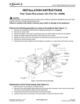
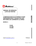
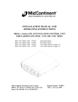
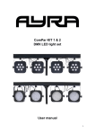
Door Latch Assembly Installation Instructions
INSTALLATION INSTRUCTIONS
REMOVAL AND INSTALLATION OF DOOR LATCH ASSEMBLY QUEST
NOTE: Removing the existing door catch/switch with the replacement catch will remove the automatic sold out reset function of the machine. This feature can still be used or totally defeated
depending on users preference.
OPTION 1: By removing the existing switch and not jumping the board the sold out will work, but not
reset unless the pump door switch is manually reset after each refill. If the switch is not manually reset
the light will not go out even after installing new product.
OPTION 2: To disable the sold out feature jumpers are added to the control board in the sold out plug
location. The sold out will now be disabled and never come on.
Installation of these options are described below.
Parts List
Description
Part Number
Qty
Bracket
720201471
1
Sold Out Jumper Board
11749
4
Jumper Switch
720302204
1
Spacer
720705306
1
Screw Plastic #8 x ¾”
07015001
2
Screw 6-32 x 3/8”
0700203
2
Washer .145x.5x .03
07301043
2
Screw 6-32 x 1/4
0700201
2
Latch
720532112
1
Catch
720202415
1
FIGURE 1
Tools Required
•
Hex Screw Driver
•
Electrical Tape
Revision Date: June 30, 2004
© 2004, IMI Cornelius Inc.
www.cornelius.com
-1-
Revision: C
Publication Number: 729011146INS
Door Latch Assembly Installation Instructions
INSTALLATION
IMPORTANT: Disconnect power from machine before starting this procedure!
1. Remove the top cover of the machine.
A. Remove two screws from rear of top.
B. To remove cover open door and pull cover
forward.
FIGURE 2
FIGURE 3
2. Remove the side panel of the machine.
A. Remove latch cover plate.
NOTE: When reassembling latch guard use
the #8 PLASTIC screws supplied.
B. Remove 2 screws holding splash guard.
FIGURE 5
FIGURE 4
C. Remove one screw from lower rear on right
side panel.
FIGURE 6
Publication Number: 729011146INS
D. Slide panel forward to remove.
NOTE: Do not loose plastic spacers located
on panel clips.
FIGURE 7
-2-
© 2004, IMI Cornelius Inc.
Door Latch Assembly Installation Instructions
3. Remove and replace door catch.
A. Remove (2) 8-32 screws holding existing
door catch.
B. Replace catch with new catch assembly.
Fasten to door with 8-32 x 5/8” screws.
FIGURE 9
FIGURE 8
4. Remove and replace cabinet catch.
A. Pull back tape back exposing catch/switch.
B. Remove and save insulation putty to be reinstalled later.
FIGURE 10
FIGURE 11
C. Remove (2) 6-32 screws holding existing
latch/switch.
D. Remove latch/switch from wire harness.
FIGURE 13
FIGURE 12
© 2004, IMI Cornelius Inc.
-3-
Publication Number: 729011146INS
Door Latch Assembly Installation Instructions
E. Insert slotted holes into new latch.
F. Attach bracket and latch to cabinet frame
using (2) 6-32 x 3/8” screws and washers.
FIGURE 15
FIGURE 14
G. Close door and adjust cabinet bracket using
the 6-32 screws. Door should slightly compress the door seal.
H. Check lower and upper door to assure seal.
If not adjust bracket until it properly seals.
FIGURE 17
FIGURE 16
5. Connect cabinet interrupt switch jumper wire.
A. Plug one end of black spade end jumper in
each end of existing cable.
B. Wrap a piece of electrical tape on both ends
to prevent wires from coming loose.
FIGURE 19
FIGURE 18
Publication Number: 729011146INS
-4-
© 2004, IMI Cornelius Inc.
Door Latch Assembly Installation Instructions
C. Route wires in existing cavity and reinstall insulation putty and replace tape.
FIGURE 21
FIGURE 20
D. Replace side panels by sliding panels forward to engage panel tabs. Make sure plastic spacers are located on panel clips before
assembling. Replace all screws that were
previously dissembled.
E. Replace latch cover plate.
NOTE: When reassembling latch guard use
the #8 PLASTIC screws supplied if holes are
stripped.
FIGURE 23
FIGURE 22
THIS COMPLETES THE LATCH ASSEMBLY PROCEDURE. If the machine is to use OPTION 1 “DOOR
RESET OPTION” allowing sold out to function complete the procedure by replacing all machine covers
and guards.
IF OPTION 2 IS SELECTED CONTINUE WITH PROCEDURE
6. Installing sold out defeat jumpers.
A. Remove screw, holding electrical box to
frame.
B. Pull control box from machine.
FIGURE 25
FIGURE 24
© 2004, IMI Cornelius Inc.
-5-
Publication Number: 729011146INS
Door Latch Assembly Installation Instructions
C. Remove cover from box.
D. Locate the 2 pin plug that says “SOLD OUT”
on the control board. There will be one for
each pump. Disconnect these connectors.
There will be (4) total in a four flavor
machine.
FIGURE 26
FIGURE 27
E. Replace the connectors with the “SOLD OUT” jumpers.
FIGURE 28
THIS COMPLETES THE LATCH ASSEMBLY PROCEDURE for OPTION 2 “SOLD OUT DISABLED
OPTION” disabling the sold out function. Complete the procedure by replacing all machine covers and
guards.
If machine does not function after reassembly make sure control box is properly seated in mating connector.
Publication Number: 729011146INS
-6-
© 2004, IMI Cornelius Inc.