1
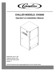
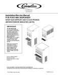
IMI CORNELIUS INC
Telephone (800) 551–4423 Fax (800) 394–5140
CHILLER
Models: CH1500–CH7500
Operator’s Manual
with Installation,
Service, and Parts
Part No. 91961OPR
September 12, 2006
Revised: N/A
Revision: A
THIS DOCUMENT CONTAINS IMPORTANT INFORMATION
This Manual must be read and understood before installing or operating this equipment
© IMI CORNELIUS INC; 2006
PRINTED IN U.S.A
TABLE OF CONTENTS
Page
GENERAL INFORMATION . . . . . . . . . . . . . . . . . . . . . . . . . . . . . . . . . . . . . . . . . . . . . . . . . .
1
INTRODUCTION . . . . . . . . . . . . . . . . . . . . . . . . . . . . . . . . . . . . . . . . . . . . . . . . . . . . . .
1
SPECIFICATION NOTES . . . . . . . . . . . . . . . . . . . . . . . . . . . . . . . . . . . . . . . . . . . . . . .
1
INSTALLATION . . . . . . . . . . . . . . . . . . . . . . . . . . . . . . . . . . . . . . . . . . . . . . . . . . . . . . . . . . . .
2
LOCATION . . . . . . . . . . . . . . . . . . . . . . . . . . . . . . . . . . . . . . . . . . . . . . . . . . . . . . . . . . . .
2
ELECTRICAL . . . . . . . . . . . . . . . . . . . . . . . . . . . . . . . . . . . . . . . . . . . . . . . . . . . . . . . . .
3
PHASE PROTECTION / 3–PHASE OPTION . . . . . . . . . . . . . . . . . . . . . . . . . . . . . 3
PHASE PROTECTION / 3–PHASE OPTION ADJUSTMENT . . . . . . . . . . . . . . . 3
PLUMBING . . . . . . . . . . . . . . . . . . . . . . . . . . . . . . . . . . . . . . . . . . . . . . . . . . . . . . . . . . .
3
WATER-COOLED CONDENSERS . . . . . . . . . . . . . . . . . . . . . . . . . . . . . . . . . . . . . . 3
CHILLER WITH RESERVOIR . . . . . . . . . . . . . . . . . . . . . . . . . . . . . . . . . . . . . . . . . . 4
AUTO REFILL OPTION . . . . . . . . . . . . . . . . . . . . . . . . . . . . . . . . . . . . . . . . . . . . . . . 4
CHILLER WITHOUT RESERVOIR . . . . . . . . . . . . . . . . . . . . . . . . . . . . . . . . . . . . . . 4
START UP . . . . . . . . . . . . . . . . . . . . . . . . . . . . . . . . . . . . . . . . . . . . . . . . . . . . . . . . . . . . . . . .
7
WATER FLOW START-UP . . . . . . . . . . . . . . . . . . . . . . . . . . . . . . . . . . . . . . . . . . . . . .
7
CHILLER WITH PUMP . . . . . . . . . . . . . . . . . . . . . . . . . . . . . . . . . . . . . . . . . . . . . . . . 7
CHILLER WITHOUT PUMP . . . . . . . . . . . . . . . . . . . . . . . . . . . . . . . . . . . . . . . . . . . . 7
THERMOSTAT ADJUSTMENT . . . . . . . . . . . . . . . . . . . . . . . . . . . . . . . . . . . . . . . . . .
7
STANDARD THERMOSTAT . . . . . . . . . . . . . . . . . . . . . . . . . . . . . . . . . . . . . . . . . . . . 7
DUAL POINT ADJUSTMENT . . . . . . . . . . . . . . . . . . . . . . . . . . . . . . . . . . . . . . . . . . 8
COOLING START-UP . . . . . . . . . . . . . . . . . . . . . . . . . . . . . . . . . . . . . . . . . . . . . . . . . 8
CONTROL PANEL . . . . . . . . . . . . . . . . . . . . . . . . . . . . . . . . . . . . . . . . . . . . . . . . . . . . 8
MAINTENANCE . . . . . . . . . . . . . . . . . . . . . . . . . . . . . . . . . . . . . . . . . . . . . . . . . . . . . . . . . . .
10
FLUID RECOMMENDATIONS . . . . . . . . . . . . . . . . . . . . . . . . . . . . . . . . . . . . . . . . . . . . . . .
11
TROUBLESHOOTING . . . . . . . . . . . . . . . . . . . . . . . . . . . . . . . . . . . . . . . . . . . . . . . . . . . . . .
13
CHILLER DOES NOT OPERATE. CONTROL POWER LIGHT “OFF” . . . . . . . . .
12
PUMP DOES NOT OPERATE. PUMP POWER LIGHT “OFF” . . . . . . . . . . . . . . .
12
PUMP DOES NOT OPERATE. PUMP POWER LIGHT “ON”. . . . . . . . . . . . . . . . .
12
CHILLER DOES NOT COOL. COOLING LIGHT “OFF”. . . . . . . . . . . . . . . . . . . . . .
12
CHILLER DOES NOT OPERATE. COOLING LIGHT “ON”. . . . . . . . . . . . . . . . . . .
12
A. LOW PRESSURE ALARM LIGHT CYCLES ON/OFF. . . . . . . . . . . . . . . . . . . . .
13
HIGH PRESSURE ALARM LIGHT “ON”. . . . . . . . . . . . . . . . . . . . . . . . . . . . . . . . . . .
13
LOW TEMPERATURE ALARM . . . . . . . . . . . . . . . . . . . . . . . . . . . . . . . . . . . . . . . . . .
13
SERVICE . . . . . . . . . . . . . . . . . . . . . . . . . . . . . . . . . . . . . . . . . . . . . . . . . . . . . . . . . . . . . . . . .
14
SAFETY CONTROLS . . . . . . . . . . . . . . . . . . . . . . . . . . . . . . . . . . . . . . . . . . . . . . . . . . . . . .
16
HIGH PRESSURE CONTROL (HPC) . . . . . . . . . . . . . . . . . . . . . . . . . . . . . . . . . . . . .
16
LOW TEMPERATURE CONTROL (LTC) . . . . . . . . . . . . . . . . . . . . . . . . . . . . . . . . . .
16
LOW PRESSURE CONTROL (LPC) . . . . . . . . . . . . . . . . . . . . . . . . . . . . . . . . . . . . . .
16
PARTS LIST . . . . . . . . . . . . . . . . . . . . . . . . . . . . . . . . . . . . . . . . . . . . . . . . . . . . . . . . . . . . . .
18
WARRANTY . . . . . . . . . . . . . . . . . . . . . . . . . . . . . . . . . . . . . . . . . . . . . . . . . . . . . . . . . . . . . .
21
i
91961OPR
TABLE OF CONTENTS (cont’d)
Page
LIST OF FIGURES
FIGURE 1. INSTALLATION DETAILS . . . . . . . . . . . . . . . . . . . . . . . . . . . . . . . . . . . . .
2
FIGURE 2. CHILLER PLUMBING SCHEMATIC WITH PUMP AND TANK
(STANDARD) . . . . . . . . . . . . . . . . . . . . . . . . . . . . . . . . . . . . . . . . . . . . . . . . . . . . . . . . . .
5
FIGURE 3. CHILLER PLUMBING SCHEMATIC NO TANK (OPTION) . . . . . . . . .
5
FIGURE 4. CHILLER PLUMBING SCHEMATIC NO PUMP, NO TANK (OPTION)
5
FIGURE 5. SAMPLE DATA PLATE FOR CH5002-A . . . . . . . . . . . . . . . . . . . . . . . .
14
FIGURE 6. REFRIGERATION PIPING SCHEMATIC WITH HOT GAS BYPASS
17
FIGURE 7. REFRIGERATION PIPING SCHEMATIC WITHOUT HOT GAS
BYPASS . . . . . . . . . . . . . . . . . . . . . . . . . . . . . . . . . . . . . . . . . . . . . . . . . . . . . . . . . . . . . .
17
FIGURE 8. CHILLER PARTS BREAKDOWN . . . . . . . . . . . . . . . . . . . . . . . . . . . . . .
18
FIGURE 9. PUMP AND TANK COMPONENTS . . . . . . . . . . . . . . . . . . . . . . . . . . . .
19
FIGURE 10. ELECTRICAL BOX COMPONENTS . . . . . . . . . . . . . . . . . . . . . . . . . .
20
91961OPR
ii
GENERAL INFORMATION
INTRODUCTION
Remcor “CH” Series Refrigerated Recirculating Water Chillers are designed to provide a continuous flow of
clean cooling water at a constant temperature and to handle a variety of closed loop and tank cooling applications.
The CH consists of a refrigeration system with associated operating controls housed in a sturdy sheet metal
cabinet. A standard pump and reservoir package provides a complete self-contained water cooling and circulating system.
CH Chillers are designed to operate in a clean laboratory or industrial environment where ambient temperatures
range from 40F to 110F. Once properly installed, the CH Chiller will run virtually maintenance free and provide
a constant supply of cooling liquid to the application.
NOTE: Please read through this manual before starting the chiller.
SPECIFICATIONS
Model
Cooling Capacity* Watts/BTU
Compressor
CH1500
CH2000
CH3000
CH5000
CH7500
5,570/19,000
8,500/29,000
12,000/41,000
18,000/61,500
25,800/85,000
1.5 H.P.
2 H.P.
3 H.P.
5 H.P.
7.5 H.P.
Air Cooled (Water Cooled Optional)
Condenser
Digital Display 30–100 F (0–39C.)
Temperature Controller
Many Available
Pump**
10 Gallons
Reservoir
Voltage (Full Load Amps)***
230/60/1(17)
230/60/3(13)
460/60/3(8)
Dimensions W x D x H (inches)
230/60/3(13)
460/60/3(8)
40 Gallons
230/60/3(16)
460/60/3(10)
230/60/3(26.5)
460/60/3(14)
230/60/3(35)
460/60/3(22)
28 x 28 41
36 x 36 x 65
3/4–inch
1–inch
Inlet/Outlet Fitting Size
SPECIFICATION NOTES
1. The figures for power and cooling capacity are listed for air-cooled units with a circulation temperature of
68 F, and ambient temperature of 80F and standard pump.
2. Cooling capacity will be affected as follows: Derate 17% for 50 Hz operation. Derate 1% for each F drop
in recirculating temperature. Derate .5% for each F increase in ambient temperature. Optional pumps will
decrease net cooling capacity.
3. The operating water temperature range for water is 40F (5C) to 100F (38C). If use of other fluids or
temperatures are required, the Technical Service Department must be contacted so the appropriate ranges
can be set.
4. Water-cooled units require about 20% less input power.
5. All CH Chillers are thoroughly tested before leaving the factory to ensure that each unit meets these specifications prior to shipment.
WARNING: Never operate the Chiller with the panels removed. Always use the power
switch to turn off the Chiller when it is not being used. Always ensure that all air inlets and
outlets are free from obstruction.
1
91961OPR
INSTALLATION
LOCATION
Install the Chiller indoors in a well ventilated area where ambient temperatures will never fall below 40F or rise
above 110F. To obtain optimum cooling capacity, the ambient temperature should be 80F or below.
Standard CH Chiller have air-cooled condensers. On air-cooled units it is important that the air intake and discharge are not obstructed. Avoid hot air discharge from other equipment or enclosed areas where heat build-up
could cause a significant rise in ambient temperatures. A minimum of two feet of space on all four sides of the
Chiller will be sufficient to prevent obstruction. Water-cooled units should be located near a water source and
drain.
TANK FILL, 1–INCH FPT
CH1500, 2000, 3000
ELECTRICAL JUNCTION BOX
CONTROL PANEL
(SEE DETAIL)
TANK FILL 1–INCH FPT
S.S. (CH5000, 7500)
TANK DRAIN
AIR OUTLET
(AIR INLET ON
OPPOSITE END)
WATER OUTLET
3/4–INCH OR 1–INCH
FPT S.S.
TANK LEVEL GAUGE
CH 5000 AND 7500
ON REAR FOR
CH1500, 2000 AND 3000
WATER INLET
3/4–INCH OR 1–INCH
FPT S.S.
FIGURE 1. INSTALLATION DETAILS
91961OPR
2
ELECTRICAL
All wiring must conform to the National Electric Code and any applicable local codes. The Chiller must be
PERMANENTLY wired by means of electrical conduit to a properly fused disconnect of proper amperage or
wired to a properly rated power cord and plugged into an outlet with the appropriate disconnect and amperage
rating. The electrical junction box located on the upper rear of the Chiller, includes a four-terminal strip for power
supply connections The DATA PLATE, located beside the junction box, indicates the actual phase, voltage and
amperage for each Chiller.
After the electrical connections are made, power must be supplied to the Chiller for a period of 12 hours (with
control switched off) to allow the compressor crankcase heater to warm the compressor lubricant.
CAUTION: On three phase applications, it is important that the rotation of the pump, when
supplied, is correct. Running the pump in reverse for more than a few seconds will result in
permanent pump damage. When the pump is running, shaft rotation must match the
direction indicated on the pump housing. If the rotation is incorrect, reverse two of the three
incoming power supply leads. The Phase Protection/3–Phase Monitor Option will prevent the
pump from operating backwards. See the option description.
Phase Protection / 3–Phase Option
The 3–Phase Monitor detects phase loss, low voltage, and phase reversal by continuously monitoring the
3–Phase power lines for abnormal conditions. When correct voltage and phase rotation are applied, the internal
relay will energize. A fault condition will de–energize the relay. When the fault is corrected, the monitor will automatically reset. Both Trip and Norm condition indicators are provided on the relay to aid in adjustment and system trouble–shooting.
This control is located in the enclosure labeled “Monitor” on top of the electrical box.
Phase Protection / 3–Phase Option Adjustment
The following procedure will allow the 3–Phase Monitor to achieve a trip point just below the nominal phase-tophase voltage, where the unit is applied.
Rotate the adjustment control fully clockwise, or until the red (Trip) indicator illuminated. Slowly rotate the adjustment control in a counter-clockwise direction, just until the green (Norm) indicator illuminates. At this point,
the 3–Phase Monitor is the most sensitive to irregular power line conditions. If nuisance tripping occurs, turn the
control slightly further counter–clockwise.
PLUMBING
Follow standard plumbing practices and local codes in making water connections. The Chiller inlet and outlet
connections are 3/4–inch or 1–inch FPT. Flexible hose and fittings are recommended for plumbing the system.
A No. 20 mesh strainer should be installed on the Chiller inlet to prevent foreign particles from entering the system and should be cleaned monthly. Lines should be routed with as few bends as possible. Prevent lines from
running near radiators, hot water pipes, etc. Any lengths of tubing that are exposed to high ambient temperatures should be insulated to prevent condensation and/or significant liquid heat loss.
Water-Cooled Condensers
Water-cooled units must be connected to a source of tap water of chilled water and a drain. The connections for
the water supply (3/4–inch FPT or 1–inch FPT) are located on the rear of the unit. These units are supplied with
a WATER REGULATING VALVE that allows only the required amount of water to pass through the condenser
for a given heat load. The water flow through the condenser can vary from 0 when the cooling system is in the
“OFF” cycle to approximately 5.0–gpm at maximum rated loads for 1–1/2 ton units and approximately 20–gpm
at maximum rated loads for 7–1/2 ton units. This valve is factory set to operate where the water supply temperature ranges from 50F (10C) to 80F (27C) with a supply pressure of 30 to 60–PSIG. For temperatures or
pressure outside these ranges, contact our Technical Service Department for assistance in “field” adjustment of
the valve. Once the system as been properly plumbed, it is important that the circulation system be filled with
water.
3
91961OPR
Chiller with Reservoir
The reservoir can be filled by removing the water fill cap located on the upper rear of the Chiller (See Fluid Recommendations page). After ensuring that the drain valve is closed, fill the reservoir via the full port with clean
water until the water level sight glass on the front of the unit indicates “FULL” the fill cap should then be reinstalled before operation begins.
Auto Refill Option
If the Chiller is provided with the Auto Refill Option, install 1/4–inch or 1/2–inch tubing from the auto refill fitting
located on the lower rear of the Chiller to a fresh water supply line. The Chiller reservoir will fill with water automatically and the proper reservoir level will always be maintained.
Chiller without Reservoir
The Chiller and system piping should be filled with clean water ensuring that all air is purged from the system.
91961OPR
4
RESERVOIR
LOW TEMP. CONTROL
FROM PROCESS
EVAPORATOR
CHILLER INLET
TO PROCESS
PUMP
BYPASS VALVE
CHILLER OUTLET
FIGURE 2. CHILLER PLUMBING SCHEMATIC WITH PUMP AND TANK (STANDARD)
FROM PROCESS
CHILLER INLET
LOW TEMP. CONTROL
EVAPORATOR
BYPASS VALVE
CHILLER OUTLET
TO PROCESS
FIGURE 3. CHILLER PLUMBING SCHEMATIC NO TANK (OPTION)
FROM PROCESS
CHILLER INLET
TO PROCESS
LOW TEMP. CONTROL
CHILLER OUTLET
EVAPORATOR
FIGURE 4. CHILLER PLUMBING SCHEMATIC NO PUMP, NO TANK (OPTION)
5
91961OPR
THIS PAGE LEFT BLANK INTENTIONALLY
91961OPR
6
START UP
WATER FLOW START-UP
Chiller with Pump
It is important to check the pump rotation on the three phase units. Remove the lower side panel to expose the
pump. Turn the pump power switch to the “ON” position for a few seconds. Observe the motor shaft to ensure
that it is turning in the direction indicated by the arrow located on the pump housing. If the rotation is incorrect,
reverse two of the three incoming power supply leads at the terminal strip. After changing the leads, check the
pump rotation.
NOTE: Running the pump in reverse for more than a few seconds will result in permanent
pump damage.
After ensuring that the system piping is free from obstruction and that all valves are open, turn the pump power
switch to the “ON” position. The pump power indicator should illuminate, indicating that the pump is operating.
All Chillers with pumps are provided with a pressure regulating valve on the pump discharge. This valve is preset at the factory to ensure that system pressure does not exceed the capabilities of the pump motor and/or piping. If this valve requires adjustment, please contact the factory for proper setting procedure and pressures.
A flow meter and throttling valve can be added in the chiller inlet line in order to monitor and/or adjust the flow
rate through the Chiller.
Once the flow has been established, the thermostat can be adjusted to the desired set-point.
Chiller without Pump
A flow meter and throttling valve can be added in the Chiller inlet line in order to monitor and/or adjust the flow
rate through the Chiller.
Once the flow has been established, the thermostat can be adjusted to the desired set-point. See thermostat
adjustment.
THERMOSTAT ADJUSTMENT
Standard Thermostat
The following procedure should be followed to adjust the standard thermostat:
1. To set the “SET POINT”, press and release the “SET” button, the current “SET POINT” will be displayed.
2. While the current “SET POINT” is displayed, press the “UP” or “DOWN” button to change the “SET POINT”
to desired temperature.
3. Release all buttons. The display will show the system water temperature after a few seconds. The “SET
POINT” can be viewed at any time by pushing the “SET” button.
The thermostat has a range that has been preset at the factory. The range is 40F (5C) to 100F (38C). If
operation outside of this range is required, please contact the Technical Service Department.
UP
DOWN
SET
7
91961OPR
Dual Point Adjustment
1. To set the “SET POINT” for Level 1. Press and release the “SET” button, Re1 should be displayed.
2. Press the “SET” button, the current SET POINT TEMPERATURE should be displayed. Press the UP or
DOWN button to change the SET POINT.
3. To set the “SET POINT” for Level 2. Press and release the “SET” button, Re2 should be displayed.
4. Press the “SET” button, the current SET POINT TEMPERATURE should be displayed. Press the UP or
DOWN button to change the SET POINT.
5. Press the fnc button to exit the program.
The thermostat has a range that has been preset at the factory. The range is 40F (5C) to 100F (38C). If
operation outside of this range is required, please contact the Technical Service Department.
Cooling Start-Up
Once flow is established and the thermostat is set to the desired set-point, turn the control power switch to
“ON”. Ensure that the air is flowing in the left side (facing the control panel) and out the right side. If not, reverse
two of the three incoming power supply leads at the terminal strip. Once again, check for correct air flow. All
alarm indicators should be extinguished and the Chiller refrigeration system will cycle in order to maintain the
established set-point.
Re-check the reservoir level to ensure that it is ”FULL” (if so equipped) and add water if necessary.
The Chiller is now ready for normal operation.
2& 3
CONTROL
POWER
4
COOLING
5
HIGH
PRESSURE
6
LOW
PRESSURE
7
LOW
TEMP.
8& 9
PUMP
POWER
Control Panel
1. TEMPERATURE INDICATOR/CONTROLLER (Thermostat)- Combines a precise temperature control and
accurate set ability with a convenient LED temperature readout that indicates system liquid temperature.
2. CONTROL POWER SWITCH- A simple (ON/OFF) switch that switches power to the control circuit. This
switch must be “ON” for the Chiller to operate.
8
91961OPR
3. CONTROL POWER LIGHT- A white light that indicates that Chiller control power is present.
4. COOLING LIGHT- A green light that indicates refrigeration system operation. This light cycles on and off in
response to the thermostat.
5. HIGH PRESSURE ALARM LIGHT- A red light that indicates high refrigeration pressure.
6. LOW PRESSURE ALARM LIGHT- A red light that indicates low refrigeration pressure.
7. LOW TEMPERATURE ALARM LIGHT- A red light that indicates and abnormally low system fluid temperature.
8. PUMP POWER SWITCH (OPTIONAL)- A simple (ON/OFF) switch that switches power to the Chiller
pump. This switch must be “ON” for the Chiller to operate.
9. PUMP POWER LIGHT (OPTIONAL)- A white light that indicates that the Chiller pump power is present.
10. LOW FLOW/HIGH TEMPERATURE INTERLOCK (OPTIONAL)- Contacts are energized when abnormally
low fluid flow or an abnormally high fluid water temperature is sensed by Chiller controls.
11. LOW LEVEL AUDIBLE ALARM (OPTIONAL)- An audible alarm that indicates an unsafe reservoir level.
9
91961OPR
MAINTENANCE
CAUTION: Disconnect electrical power before performing any of the following maintenance
procedures.
The Chiller will require very little normal maintenance.
1. On AIR-COOLED Chillers, the condenser fins should be cleaned by blowing compressed air through the
condenser from the fan side as required to eliminate any dirt or debris that may accumulate over time. This
can severely reduce the performance of the Chiller. Cleanable air filters are available as an option. Contact
the factory for information.
2. On AIR-COOLED Chillers the condenser fan motor should be lubricated every 6–months with a few drop
of SAE10 oil.
3. The pump motor should be lubricated with thirty drops of SAE20 oil once a year.
4. The circulation system should be drained and flushed periodically to avoid build-up and possible restriction of flow by contaminates.
5. The strainer at the Chiller inlet should be removed and cleaned monthly.
91961OPR
10
FLUID RECOMMENDATION
Chillers are designed to operate with water to provide maximum performance for temperatures of 40F–100F.
Distilled Water
Acceptable
De–Ionized Water
(1–5 MEG/OHMS)
Acceptable
De–Ionized Water
(5+MEG/OHMS)
Acceptable with Stainless Steel & PVC only
*No Copper or Brass
Propylene Glycol
(Lab & Industrial Grade)
Acceptable – 30% Glycol/70% Water
*For Applications with Temperatures below 40F
Lab & Industrial Grade Ethylene Glycol
Acceptable – 30% Glycol/70% Water
*For Applications with Temperatures below 40F
Mineral/Hydraulic Oils
(Viscosity<50 Centistrokes)
Acceptable
Ethylene Glycol
(Commercial/Automotive Antifreeze)
NOT Acceptable
*Silicate Rust Inhibitors in Automotive/Commercial Antifreeze will damage pump seals and
housing which lead to failure.
Acidic/Basic Solutions
(Above 8/Below 6 PH)
Not Acceptable
Mineral/Hydraulic Oils
(Viscosity>50 Centistrokes)
Not Acceptable
For questions regarding special or other fluids contact IMI Cornelius at 800–238–3600.
To Purchase Lab or Industrial Glycol contact:
IMI Cornelius
(800) 551–4423 – Part# 111521000 5 gallons
Bevcore
(866) 275–6392 – Part#1008534 Chem Glycol Food Grade 5 gallon
11
91961OPR
TROUBLESHOOTING
IMPORTANT: Only qualified personnel should service internal components or electrical wiring.
WARNING: If repairs are to be made to the refrigeration system, make sure electrical power
is disconnected from the unit.
Trouble
CHILLER DOES NOT
OPERATE. CONTROL
POWER LIGHT “OFF”
PUMP DOES NOT OPERATE.
PUMP POWER LIGHT “OFF”
PUMP DOES NOT OPERATE.
PUMP POWER LIGHT “ON”.
CHILLER DOES NOT COOL.
COOLING LIGHT “OFF”.
Probable Cause
Remedy
A.
Control power switch “off”.
A.
Turn the control power switch to
the “on” position.
B.
No power.
B.
Check the fuse and circuit
breaker.
C.
Defective power supply
connection.
C.
Check wiring and correct loose or
poor connections.
D.
Defective control power
switch.
D.
Replace the switch.
E.
Defective control transfromer.
E.
Replace the transformer.
F.
3–Phase Monitor tripped
F.
Check for correct voltage level on
each phase of incoming 3–Phase
power. Check for correct phase
rotation.
A.
Pump power switch “off”.
A.
turn the pump power switch to the
“on” position.
B.
Defective pump power switch.
B.
Replace the switch.
C.
Defective control transformer.
C.
Replace the transformer.
A.
No water in reservoir.
A.
Fill reservoir.
B.
Restriction in the line to or
from the Chiller.
B.
Remove restriction.
C.
Open or defective pump
overload relay.
C.
Manually reset the relay or
replace if necessary and check
amp setting on overload.
D.
Defective pump contactor.
D.
Replace the pump contactor.
E.
Defective pump motor or
damaged impeller.
E.
Replace the pump or impeller.
A.
Defective thermostat.
A.
Replace thermostat.
A.
Process water too cold.
A.
Increase the thermostat setting.
B.
Low process water flow.
B.
Ensure that there is adequate flow
through the process piping.
C.
Defective expansion valve.
C.
Replace the expansion valve.
CHILLER DOES NOT
OPERATE. COOLING LIGHT
“ON”.
A. LOW PRESSURE ALARM
LIGHT CYCLES ON/OFF.
91961OPR
12
Trouble
HIGH PRESSURE ALARM
LIGHT “ON”.
LOW TEMPERATURE ALARM
Probable Cause
Remedy
D.
Refrigerant loss.
D.
Check the sight glass. If bubbles
are seen flowing through it, the
Chiller needs to be leak checked
and recharged with refrigerant.
E.
Water bypass valve failed.
E.
Consult technical service
department.
F.
Defective pump.
F.
Replace pump.
A.
Restricted condenser airflow.
A.
Clean the fins of the condenser
and ensure that the air flow is not
restricted.
B.
Defective condenser fan
and/or motor.
B.
Check to ensure that the fan
blade is not blocked. Replace the
fan motor if necessary.
C.
Defective expansion valve.
C.
Check to ensure that the fan
blade is not blocked. Replace the
fan motor if necessary.
D.
Low or no condenser water
flow.
D.
Ensure that there is adequate flow
throught piping to condenser.
A.
Low or no process liquid flow.
A.
Ensure that there is adequate flow
through the process piping.
B.
Defective thermostat.
B.
Replace the thermostat.
C.
Pro cess water too cold below 35 F.
C.
Increase the thermostat setting.
13
91961OPR
SERVICE
When servicing a Chiller, it is important to note the information contained on the data plate located in the upper
rear of the unit.
If technical assistance is needed, the phone technician will need the Serial Number of your Chiller. That information is found on the Data Plate along with the model number, voltage requirements and refrigerant information.
The Serial Number is also needed when replacement parts are being ordered or for any warranty claims.
MADE IN U.S.A.
REMCOR PRODUCTS COMPANY
GLENDALE HEIGHTS, IL. 60139–2268
PART NO.
VOLTS
MODEL NO.
HZ
PH
SERIAL NO.
AMPS
R134A
BAR CODE
FIGURE 5. SAMPLE DATA PLATE FOR CH5002-A
Be sure to include the serial number on any documentation or billing information.
91961OPR
14
THIS PAGE LEFT BLANK INTENTIONALLY
15
91961OPR
SAFETY CONTROLS
Each Chiller is provided with three standard safety controls. These controls are arranged in series in the control
circuit to automatically shut down the unit in the event that a condition exists which could be harmful to the refrigeration system components. This section includes a brief description of each control, its location and some
troubleshooting hints that may be helpful.
HIGH PRESSURE CONTROL (HPC)
This control prevents system operation in the event that the high side pressure exceeds 350 PSIG. If this occurs, check the following:
1. That the condenser is clean and that the air inlets and outlets are unobstructed.
2. That the ambient temperature at the chiller location is below 110F.
3. That the fan blade is rotating.
Press the reset button located on the front of the control to restart the chiller. This control is located in the upper
left hand corner of the electric box. If the control opens again, check the control setting with refrigeration
gauges. If the setting is correct, contact technical service department.
LOW TEMPERATURE CONTROL (LTC)
This control prevents system operation in the event that the fluid inside the evaporator falls below 35F. If this
occurs, check the following:
1. That the thermostat set point is set at 40F or greater.
2. That the flow through the system is greater than 2 gallons per minute.
This control is mounted in the lower left hand corner of the electric box. It automatically resets itself once the
water temperature is restored to 38F. The low temperature control may be adjusted for lower temperatures if a
glycol solution is used. Contact Technical Service Department for temperatures below those stated here (See
Fluid Recommendations page).
LOW PRESSURE CONTROL (LPC)
This control prevents system operation in the event that the low side pressure falls below 44 psi. If this occurs,
check the following:
1. That the thermostat set point is set at 40F or greater.
2. That the flow through the system is greater than 2 gallons per minute.
3. That no bubbles are present in the sight glass.
4. That water bypass valve allows flow through the Chiller in a “dead head” situation.
This control is located to the right of the high pressure control in the electric box. It automatically resets itself
once the low side pressure rises to approximately 64 psi. If the control opens again, check the control setting
with refrigeration gauges. If setting is correct, contact Technical Service Department.
91961OPR
16
LIQUID LINE
SOL. VALVE
SIGHT GLASS
FILTER/DRIER
TXV
LIQUID
RECEIVER
EVAPORATOR
HOT GAS
BYPASS
VALVE
TXV EQUALIZER
LINE
CONDENSER
TXV SENSING
BULB
COMPRESSOR
LOW PRESSURE
SWITCH
HIGH PRESSURE
SWITCH
FIGURE 6. REFRIGERATION PIPING SCHEMATIC WITH HOT GAS BYPASS
SIGHT GLASS
FILTER/DRIER
TXV
LIQUID
RECEIVER
TXV EQUALIZER
LINE
EVAPORATOR
CONDENSER
TXV SENSING
BULB
COMPRESSOR
LOW PRESSURE
SWITCH
HIGH PRESSURE
SWITCH
FIGURE 7. REFRIGERATION PIPING SCHEMATIC WITHOUT HOT GAS BYPASS
17
91961OPR
PARTS LIST
4
8
23
12
18
24
13
6
14
7
25
15
11
20
17
16
3
21
19
9
22
10
5
1
4
26
10
FIGURE 8. CHILLER PARTS BREAKDOWN
Index
No.
1
2
3
4
5
6
7
8
9
10
11
12
13
14
15
Description
1/2” FPT Coupling
Thermowell, Low Temp. Thermostat (Not Shown)
Corner Cover
Side Panel
Rear Panel
Upper Front Panel
Lower Front Panel
Lid
Control Panel
FPT Coupling
Temperature Control
Electric Box Assembly
Fan Blade
Fan Motor
White Switch/Indicator
91961OPR
Index
No.
16
17
18
19
20
21
22
23
24
25
26
NS
NS
Description
Red Indicator
Green Indicator
Compressor
Accumulator
Filter/Drier
TX Valve, R-22
Evaporator Assembly
Condenser
Compressor
Receiver
Caster
Condenser, Water Cooled
Regulating Valve, Water Cooled Condenser
* Call the Techncial Service Department for
Proper Panel.
18
3
5
2
1
4
FIGURE 9. PUMP AND TANK COMPONENTS
Index
No.
1
2
3
Index
No.
Description
Thermowell, Temperature Control
Temperature Probe
Tank Assembly
4
5
Description
Pump
Pump Relief Valve
** Call the Service Department for proper pump
identification.
19
91961OPR
4
5
1
2
6
7
3
FIGURE 10. ELECTRICAL BOX COMPONENTS
Index
No.
1
2
3
4
5
Description
Low Temperature Thermostat
Control Transformer
Contactor, Compressor
High pressure Control
Low Pressure Control
91961OPR
Index
No.
6
7
20
Description
Contactor, Pump
Overload Relay, 1.0 to 1.6A
Overload Relay, 1.4 to 2.0A
Overload Relay, 2.0 to 3.0A
Overload Relay, 2.8 to 4.4A
Overload Relay, 4.0 to 6.0A
WARRANTY
IMI Cornelius Inc. warrants that all equipment and parts are free from defects in material and workmanship under normal use and service. For a copy of the warranty applicable to your Cornelius, Remcor or Wilshire product, in your country, please write, fax or telephone the IMI Cornelius office nearest you. Please provide the
equipment model number, serial number and the date of purchase.
Locate the office in your area on the Cornelius web site, www.cornelius.com, under the contacts tab.
21
91961OPR
IMI CORNELIUS INC.
www.cornelius.com


![Service Manual FCB Pinnacle 2 and 4 Flavor [ 005271 ]](http://vs1.manualzilla.com/store/data/006038828_1-2ffb9d6cd82d544c3f733521619945ce-150x150.png)