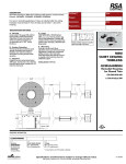
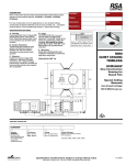
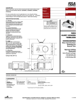
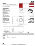
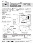
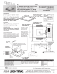
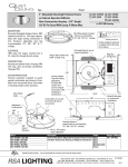
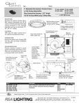
1
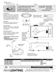
INSTALLATION INSTRUCTIONS V90168A
QUIET CEILING REMODEL W/ROUND TRIM
Model: QCM504RM with QCM5001-5004
C
UL
US
R
Electrical Connection (Con't)
Avoid Fire or Electric Shock
*Installation Instructions for qualified electricians only.
*Install per National Electrical Code and local regulations.
*Read Installation Instructions completely before installation.
*Failure to follow Installation Instructions may void warranties.
Lamp
Socket
Wiring
To Existing Electrical Service
THIS PRODUCT MUST BE INSTALLED IN
ACCORDANCE WITH THE APPLICABLE
J-Box
INSTALLATION CODE BY A PERSON FAMILIAR
WITH THE CONSTRUCTION AND OPERATION OF
THE PRODUCT AND THE HAZARDS INVOLVED.
Flex Cable
Pre-Installation Preparation
1. Check for Above Ceiling Clearance of 5-1/2". See Fig. 1.
Transformer Assy
2. Make 7-1/4" diameter Cutout in Ceiling. See Fig. 1.
Figure 2
Above Ceiling Clearance
Installation Of Housing
Fixture
5-1/2"
1. Remove factory installed Wiring Access Door on Fixture. See Fig. 3.
Retain Wing Nuts and Door for re-installation.
2. Fold three (3) Rotational Clamp Brackets tight against Fixture (See Fig.
Ceiling
4) making sure Brackets are in upper most (highest) threaded position
(See Fig. 5) to accommodate largest ceiling thickness.
7-1/4"
3. Insert Fixture into Ceiling Cutout (See Fig. 1), rotating to orient Square
Cutout
Aperture to desired position relative to adjacent wall(s), other fixtures,
aperture alignments, etc.
Figure 1
4. OPTIONAL: Retain orientation by installing two (2) or three (3)
Electrical Connection
drywall/zip screws into outer perimeter of Perforated Mudding Frame.
5. Holding Fixture firm to ceiling surface, drive clockwise the three (3) #8 x
1. Turn OFF Electrical Service.
3" Set Screws (See Fig. 5) located on the underside of Perforated
2. All appropriate electrical "rough" wiring should be completed.
Mudding Frame (See Fig. 6) to rotate and lock the Rotational Clamp
3. Connect wiring inside J-Box (See Fig. 2) to Existing Electrical Service
Brackets to the ceiling. DO NOT overtighten the Screws or Rotational
through Knockout provided.
Clamp Brackets. (Overtightening may crack ceiling material.)
NOTE: Single circuit cable only and/or single fixture with next fixture
6. Reach inside and through Fixture Wiring Access Opening and locate
jumper. Wire single fixture or wire through with second cable (to next
Lamp Socket, Flex Cable, J-Box/Transformer Assembly. See Fig. 6.
fixture) in J-Box.
7. Pull Lamp Socket and Lamp Wiring into inside of Fixture. See Fig. 6.
4. Carefully insert wired J-Box, Transformer Assembly, Flex Cable and
8. Slide Conduit Ring (See Fig. 6) into Slot (See Fig. 5) in Wiring Access
Lamp Socket through Ceiling Cutout into available ceiling area (around
Opening.
cutout) avoiding all insulation and combustable surfaces by 3" all around. 9. Re-install Wiring Access Door over Conduit Ring. Secure with Wing
Nuts removed earlier.
RSA Lighting
Visit our web site at: www.rsalighting.com
7945 Orion Ave, Van Nuys, CA 91406 818-349-3030/ 800-356-3030 FAX 818-349-3031