1
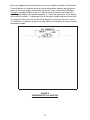
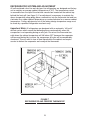
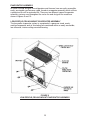
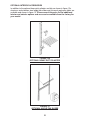
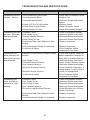
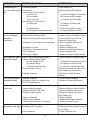
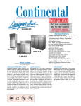
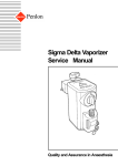
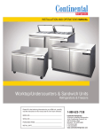
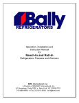
Operation, Installation and
Instruction Manual
for
Reach-In and Roll-In
Refrigerators, Freezers and Warmers
A Division of National Refrigeration & Air Conditioning Products, Inc.
539 Dunksferry Road • Bensalem, PA 19020-5908
215-244-1400 • 1-800-523-7138 • Fax: 215-244-9579
www.continentalrefrigerator.com
REV:102004
Operators Manual
Table of Contents
Page
Receiving Your New Model............................................................................................3
General Information And Important Operating Facts ....................................................3
Uncrating Your New Model ............................................................................................4
Installation And Location ................................................................................................4
Clearances ..........................................................................................................4
Ventilation ............................................................................................................4
Floor Loads ........................................................................................................5
Installing Legs And Leveling Reach-In Models ..................................................6
Mounting Roll-In Models In Place And Leveling ................................................6
Installing Casters And Leveling Reach-In Models ..............................................7
Installing Condensate Evaporator ......................................................................8
Removal Of Doors And Door Adjustment............................................................9
Removal Of Grill ................................................................................................10
Initial Cleaning Procedure ............................................................................................10
Start-Up Procedure ......................................................................................................11
Electrical Connections........................................................................................11
115 Volt, 60 Hz, 1 Phase Connection ................................................................11
208-230 Volt, 60 Hz, 1 Phase Connection ........................................................11
Special Voltage Connections..............................................................................11
Start-Up Checklist ..............................................................................................12
Remote Applications ..........................................................................................12
Operation ......................................................................................................................13
Thermometer Calibration ..................................................................................13
Calibration Check ..............................................................................................13
Dial Thermometer ..............................................................................................13
Digital Thermometer ..........................................................................................13
Refrigerator System And Adjustment ................................................................15
Freezer System And Adjustment........................................................................16
Defrost Operation ..............................................................................................16
Warmer System And Adjustment ......................................................................17
Evaporator Assembly ........................................................................................18
Low-Profile,Ceiling-Mount Evaporator Assembly ........................................18
Plug-Type,Top-Mount Evaporator Assembly ................................................19
Interior Reach-In Accessories ............................................................................20
Shelving Installation......................................................................................20
Optional Interior Accessories........................................................................21
Safety Precautions ............................................................................................22
Maintenance ................................................................................................................22
Periodic Cleaning Procedure ............................................................................22
Sliding And Hinged Glass ..................................................................................23
General Preventative Maintenance....................................................................23
Parts And Service ..............................................................................................24
Troubleshooting And Servicing Guide ..........................................................................25
Wiring Diagrams ..........................................................................................................28
Warranty........................................................................................................................36
RECEIVING YOUR NEW MODEL
Congratulations on your recent purchase of continental refrigerator superior food
equipment products! When your shipment arrives, please thoroughly examine the
shipping crate for any punctures, dents, or signs of rough handling. It is in your best
interest to partially remove or open the shipping container in order to examine the
model for any concealed damages which may have occurred during shipment. If the
model is damaged, it must be noted on the delivering carrier's delivery slip or bill of
lading (see “filing a damage claim” under warranty section).
GENERAL INFORMATION AND IMPORTANT OPERATING FACTS
This manual has been compiled to aid in the installation, operation and maintenance
of your new equipment. Please take the time to read all of the material in order to
become more familiar with your equipment and its operation, and enjoy optimum
performance.
Important Note: All value and designer line freezers have an energy-saving fan
delay control to prevent the interior fans from operating until the evaporator coil
becomes chilled. Therefore, on initial start-up, the fans will not turn on immediately.
This is a normal mode of operation. Allow sufficient time for the evaporator coil
to reach its operating temperature (approximately 20 minutes).
No floor drains or plumbing connections are required since all models are completely
self-defrosting and use an automatic defrost condensate water evaporating system
(see “condensate evaporator installation” under installation and location section).
All cabinets must be given sufficient time to reach normal operating temperature
before placing any food inside. For refrigerators, approximately 2 hours of operation
are required to lower the cabinet temperature to 40°F. Freezers require approximately
4 hours of operation to lower the cabinet temperature to 0°F (see “operation” section
for further information).
Never overload top shelf with product so as to block or restrict cabinet airflow. Doing
so will result in poor performance, decrease in efficiency and possible need for service
to de-ice evaporator.
Prior to factory shipping, all models are performance run tested for a minimum of 12
hours providing a highly sophisticated temperature analysis recording exclusive to
each individual cabinet. This recording is supplied within this manual packet. A final
leak check, vibration, noise level and visual examination is made by a qualified quality
control team to assure a quality product. The carrier signs to this effect when he
accepts the product for shipping. To insure the maximum in safety and sanitation, all
models are listed under the reexamination service of underwriter's laboratories and
with the national sanitation foundation.
4
UNCRATING YOUR NEW MODEL
The shipping container should remain on your model as protection against dents
or scratches while transporting it to the actual set-up location. Remove the shipping
container only at the last possible moment by following these simple steps:
1. Using a pry bar, pry off and remove crate end bottom staples.
2. Pry off and remove crate front and rear bottom staples.
3. Slide crate upward and remove it, being careful not to rub against cabinet.
There are up to four (4) bolts securing the cabinet to the wooden skid. The bolts are
located at each end on the underside of the skid. In order to remove these bolts it is
advisable to tilt the cabinet backwards and place wooden blocks at each end in order
to hold it in its tilted position. Using a 3/4" socket or open end wrench, remove the bolts
and carefully slide the model off of the skid. After skid removal, the cabinet should
never be moved without dollies or rollers to avoid damage to the cabinet bottom or
floor.
Important Note: Do not under any circumstances lay your new model on its front
or sides. Only for a brief period, may you lay the model on its back and only then,
when its properly blocked so as not to crush the condensate drain tubing and also
to allow provision for your hands in order to set it in its upright position without
inflicting damage to the cabinet. Do not plug in and operate model for at least
three (3) hours after cabinet is set upright from being on its back as damage
could result to the compressor.
INSTALLATION AND LOCATION
CLEARANCES
Before moving the cabinet to its final point of installation, accurately measure all doorways or passages to assure clearance. If additional clearance is needed, cabinet doors
and grill can be easily removed (see instructions outlined in “removal of doors” and
“removal of grill” sections).
VENTILATION
The final location site of your air cooled refrigerator or freezer must be able to provide
a large quantity of cool, clean air. The refrigeration system operates most efficiently
and trouble-free with cool, dry air circulation. Avoid locations near heat and moisture
generating equipment such as stoves, ovens, cooking ranges, fryers, dish washers,
steam kettles, etc., and also direct sunlight where temperatures can be in excess of
100°F. Also, do not select a location in an unheated room or area where temperatures
may drop below 55°F. Air supply to the condensing unit is equally important. Restricting
the air supply will place an excessive heat load on the condensing unit and adversely
effect its operating efficiency.
5
Important Note: To assure sufficient air supply and circulation to the condensing
unit, a minimum clearance of 12" above the grill and 3" on each side and back of the
cabinet must be provided (see figure 1). If necessary, special venting or air supply
ducts must be installed by the installer for this purpose. Do not at any time obstruct
the grill area in front of the cabinet in any way, and never place or store anything on
top of the cabinet machine compartment. These rules are essential for maximum
cooling capacity and long life of refrigeration parts.
FIGURE 1
MINIMUM CLEARANCE DIMENSIONS
FLOOR LOADS
The floor at the final location site must be level, free of vibration and strong enough
to support the total combined weights of your new model plus the maximum product
load which might be placed into it. A fully loaded reach-in or roll-in model may reach
2,000 - 3,000 pounds. To estimate the possible product load weight, assume that
each cubic foot of storage space weighs approximately 35 pounds. Multiply 35
pounds by the amount of cubic feet in the cabinet and obtain the product load weight.
For example, a 20 cubic foot refrigerator can hold approximately 700 pounds of
product (35 x 20) and assuming the refrigerator itself weighs 300 pounds, the total
combined weight of cabinet and product is approximately 1000 pounds. Therefore,
the floor in this example must be capable of supporting up to 1000 pounds.
6
Your roll-in model comes with one cart ramp per door opening. To install the ramp(s),
simply open the cabinet door and position the ramp slots onto the screws located
along the cabinet bottom front. If the door wiper rubs along the ramp to the extreme
where the door will not self-close, you will need to adjust the door (see “door adjustment” section) or level the cabinet as explained above.
Important Note: It is extremely important that your new reach-in or roll-in model is
perfectly level for proper operation. If it is not level, the following adverse conditions
will become apparent:
1. The door(s) will not be properly aligned and consequently will not provide a
good seal. Roll-in door wiper(s) may bind.
2. Your model will run excessively due to improper door seal(s).
3. An excessive amount of ice will accumulate inside the cabinet, around the
door opening(s) and especially on the finned evaporator coil. If allowed to
continue, ice will eventually block the coil and the model will fail. This will
result in the loss of all food stored within the cabinet.
4. Defrost water will fail to drain properly and will overflow the evaporator coil
drain pan and into the cabinet of both refrigerator and freezer models.
INSTALLING CASTERS AND LEVELING REACH-IN MODELS
If you wish to install casters on your new reach-in model, follow the steps above
for “installing legs” to install the casters, making sure again that the casters are
tightened extremely well (see figure 3). If the casters are not installed tightly, the
cabinet will sway or rock with each opening or closing of the doors, possibly causing
damage to the case bottom.
To assure that your cabinet is level, caster cups must be installed under the casters
which need leveling. Caster cups are not provided with your new model but can be
purchased at most hardware or furniture stores. Do not attempt to level casters by
unscrewing them from the case bottom as this will cause damage to the cabinet
bottom and leg hole threads, voiding all warranties.
FIGURE 3
CASTERS MUST BE TIGHT TO CABINET BOTTOM
8
INSTALLING CONDENSATE EVAPORATOR
No floor drains or plumbing connections are required since all models use an
automatic condensate water evaporating system. All designer line models utilize
a unique hot gas condensate water evaporating system which is completely selfcontained and no further assembly or maintenance is required (these models are
recognized by their evaporator coil which is located out of the food zone in an
insulated plug-box housing next to the condensing unit). All value line models are
supplied with an electric condensate evaporator pan and mounting bracket packed
in the accessory carton. To install the condensate pan on value line models only,
remove both mounting screws located on the bottom of the cabinet back and install
the mounting bracket on the case bottom as shown in figure 4. Slide the condensate
pan onto the bracket, install the drain tube into the pan making sure it is not blocked
or kinked, and plug the ten foot power cord into the receptacle labeled “vaporizer”
located on the case top electrical box.
IMPORTANT NOTE: It is extremely important to be sure that the condensate
pan is plugged into its correct receptacle labeled “vaporizer” and that the condensing unit is plugged into its correct receptacle labeled “condensing unit”.
FIGURE 4
CONDENSATE EVAPORATOR INSTALLATION
9
REMOVAL OF DOORS AND DOOR ADJUSTMENT
During installation, it may become necessary to remove the cabinet doors to
facilitate passage through narrow doorways or hallways. To remove a door, pry
off all hinge covers using a sharp tool or knife (see figure 5). Swing the door to
the open-door position (90°) and carefully lift the door upward, removing the
door from the hinge bodies. If it is necessary to remove the hinge bodies from
the cabinet face, be extremely careful not to lose the light switch pin located inside
all top hinge bodies. To reinstall the door, reverse the above procedure.
All doors have been aligned at the factory, however vibration during transportation
may cause doors to shift and realignment may be necessary. If the door(s) require
realignment, proceed as follows:
1. Pry off all hinge covers using a sharp tool or knife.
2. For each door, loosen the screws which secure the hinge bodies to the
cabinet face and slide the door into alignment. Hold the door firmly in place
and tighten all screws securely.
If the door gasket(s) do not seal properly to the cabinet face and there are gaps
between the gasket and the face on the hinge edge, proceed as follows:
1. For each door, loosen all screws which are directed into the edge of the
door and push the door towards the cabinet eliminating the gap. Hold the
door firmly in place and tighten all screws securely.
2. Replace all snap-on hinge covers.
FIGURE 5
DOOR ADJUSTMENT AND REMOVAL
10
REMOVAL OF GRILL
To remove the grill, loosen all four (4) grill mounting screws located on the backside
of the grill one or two turns. Simply lift grill up off of its mounting screws and out. To
replace the grill, line up the grill mounting screws with the keyhole slots located on
the cabinet body, push in on the grill and down.
Important note: If the model is provided with a digital or dial thermometer, the
front grill cannot be completely removed from the cabinet without first removing the
thermometer bulb from inside the cabinet. However, enough capillary tubing and/or
wiring cable has been provided to allow the grill to be laid across the top of the
cabinet after it has been removed. Take care not to damage the capillary tubing
when handling the grill.
If it is necessary to remove the thermometer bulb from inside of the cabinet,
first locate the thermometer bulb cover and remove the thumbscrews securing
it in place. On value line models, the thermometer bulb cover is located on the
interior top left corner towards the front of the cabinet. On designer line models,
the thermometer bulb is located on the interior top under the air duct. Once the
cover is removed, carefully grasp the bulb and push it back through the cabinet
hole. The thermometer bulb and grill can now be removed from the cabinet. When
reinstalling the thermometer bulb, be sure to replace the permagum sealant
around the hole after inserting the bulb.
INITIAL CLEANING PROCEDURE
Prior to start-up and before placing any food inside of your new reach-in or roll-in
model, the interior of the cabinet should be thoroughly cleaned. Washing with a
mild soap and warm water solution is recommended for cleaning the aluminum
and stainless steel surfaces of your cabinet. This should be followed by cleaning
with a baking soda solution (three (3) tablespoons of baking soda to each quart of
warm water). Rinse thoroughly with clear water and dry with a clean, soft cloth.
Important Note: Never use harsh detergents, cleaners, scouring powders or
chemicals when cleaning your model. Failure to dry the interior surfaces after
cleaning may result in a streaking or staining of the metal.
Complete cleaning procedures and precautions are listed in the “periodic cleaning
procedure” under the maintenance section.
11
START-UP PROCEDURE
ELECTRICAL CONNECTIONS
To insure proper operation, your new model must be connected to an individual circuit
that can supply the full voltage as stated on the cabinet serial data plate. For correct
voltage, power draw, and wire accommodations, check the data on the serial data
plate located on the inner right wall of your new model. Verify that this information
exactly matches the electrical characteristics at the installation location. An electrical
wiring diagram, located on the upper cabinet end panel next to the electrical console
box, should also be consulted during connection.
Important Note: The condensing unit supplied with all self-contained models is
designed to operate with a voltage fluctuation of + 10 % of the voltage indicated on
the cabinet serial data plate. Full voltage of the correct service, on an individual line
not affected by the operation of other electrical appliances, must be available to the
condensing unit at all times. Burnout of the compressor due to exceeding the
high or low voltage limits is easily detected and will automatically void the
factory warranty.
115 VOLT, 60 HZ, 1 PHASE CONNECTION
All 115 volt models are provided with a U.L. approved power cord and polarized plug
which is factory installed.
Warning: Any alterations to this cord and plug could cause an electrical
hazard and will void the factory warranty.
To insure proper operation, this equipment must be plugged into a NEMA 5-15R
compatible, grounded receptacle that can supply the full voltage as stated on the
serial data plate.
208-230 VOLT, 60 HZ, 1 PHASE CONNECTION
All 208-230 volt models are to be permanently connected and are provided with
four (4) field wiring leads which exit the electrical console box located in the
machine compartment behind the front grill. The cabinet circuitry is 115 volts
and the condensing unit is 208-230 volts in which the wiring includes a neutral
and a mechanical ground. This wiring should be connected to the appropriate
power source by a qualified electrician and must conform to all local electrical
codes.
SPECIAL VOLTAGE CONNECTIONS
When models are ordered from the factory with special, optional voltages, connections
should be made as required on the electrical wiring diagram provided on the upper
cabinet end panel next to the electrical console box.
12
START-UP CHECKLIST
After your model has been installed, leveled, cleaned, and electrically connected
in accordance with this manual, please take the time before start-up to observe the
following precautions to assure trouble free operation:
1. Check that all exposed refrigeration lines are free of severe dents or kinks.
2. Check the condenser fan and evaporator fans for freedom to rotate without
any obstructions
3. Make sure that the cabinet is properly leveled (see “leveling” under
installation and location section).
The system should run smoothly and quietly in accordance with generally accepted
commercial standards. If any unusual noises are heard, turn the unit off immediately
and check for any obstructions of the condenser or evaporator fans. Fan motors, fan
blades, or fan housings can be jarred out of position through rough handling in transit
or during installation.
Important Note: All freezer models have an energy-saving fan delay control
to prevent the interior fans from operating until the evaporator becomes chilled.
Therefore, on initial start-up, the fans will not turn immediately. This is a normal
mode of operation. Allow sufficient time for the evaporator coil to reach its
operating temperature (approximately 20 minutes).
Caution: If unit is unplugged or disconnected for any reason, allow several
minutes (5-6 minutes) before turning the unit back on to allow the system
pressures to equalize. Disregarding this procedure could cause an overload
and prevent the unit from operating.
REMOTE APPLICATIONS
All models are available for purchase as remote models in which case the condensing
unit is purchased separately and installed at the time of installation. All remote models
are equipped with an expansion valve located within the evaporator coil housing,
and both liquid and suction lines stubbed and extending out from the cabinet case
top behind the front grill. Installation of the refrigeration accessories, condensing
unit, and electrical hook-up should be performed by qualified refrigeration personnel
of a competent refrigeration company only.
13
OPERATION
All cabinets must be given sufficient time to reach normal operating temperature
before placing any food inside. Refrigerators are designed to maintain an ideal
cabinet temperature of 38°F to 40°F (3.3°C to 4.4°C) and approximately 2 hours of
operation are required to reach this temperature. Standard freezers are designed to
maintain an ideal cabinet temperature of -2°F to 0°F (-18.9°C to -17.8°C) and
approximately 4 hours of operation are required to reach this temperature. Low
temperature freezers are designed to maintain an ideal cabinet temperature of 16°F to -14°F (-26.7°C to -25.6°C) and approximately 6 hours of operation are
required to reach this temperature.
THERMOMETER CALIBRATION
After your new model has been given sufficient time to pull down to the above
specified temperature range, the exterior thermometer located on the upper grill
must be checked for calibration accuracy. All thermometers are carefully calibrated
at the factory prior to shipping but may be vibrated out of calibration through rough
handling in transit, shipping vibration, or during installation.
CALIBRATION CHECK
To check calibration, an accurate, mercury thermometer (within the temperature
range of your model) must be placed inside of the cabinet on the center shelf for
at least 15 minutes without any door openings. At this time, note the temperature
on the exterior cabinet thermometer, quickly open the door and compare it to the
interior thermometers temperature. Whatever the difference (if any) is the amount
the exterior thermometer must be adjusted.
The adjustment procedure varies depending on which thermometer is equipped with
your model (see figure 5).
DIAL THERMOMETER
For a dial thermometer, carefully pry the clear plastic lens cover from the thermometer
body using a slotted screwdriver. To adjust the needle, hold the center hub stationary
using a small slotted screw driver and very carefully grasp and turn the needle to the
desired temperature using your fingers. Replace the lens cover and recheck the
calibration.
DIGITAL THERMOMETER
For a digital thermometer, note how many degrees the digital display needs to be
increased or decreased. Press twice directly on the mylar display towards the right
center using your finger. After pressing the first time, the display should read “cal”
indicating that you are in the calibration mode and after pressing the second time,
the display should read either zero or a positive number or a negative number (this
number is the point of origin for calibration). If your digital display needed to be
increased, you must advance the point of origin by that many degrees by pressing
directly on the mylar display towards the left top. If your digital display needed to be
decreased you must decrease the point of origin by
14
that many degrees by pressing directly on the mylar display towards the left bottom.
Once calibration is complete return to normal temperature mode by pressing once
again on the mylar display towards the right center. Now, recheck the calibration.
Example: the digital display reads 45°F and the internal thermometer reads 40°F
so, the digital display must be decreased by 5°. Press the right center of the display
twice and the number -1 is displayed (this is the point of origin and could have been
any number). Now, press the top left of the display five times to make the -1 go to
-6. Calibration is complete so press the right center of the display to return to normal
temperature mode.
FIGURE 6
THERMOMETER CALIBRATION
15
REFRIGERATOR SYSTEM AND ADJUSTMENT
All self-contained value line and designer line refrigerators are designed and factory
set to maintain an average cabinet temperature of 38°F. The temperature control
is accessible from the top of the electrical console box located on the cabinet top
behind the front grill (see figure 6). If an adjustment is necessary to maintain the
above temperature range only, place a screwdriver into the thermostat slot and turn
clockwise for a colder cabinet temperature or counterclockwise for a warmer cabinet
temperature. Further adjustments out of the factory design temperature range must
be made by a qualified refrigeration mechanic only.
Important Note: All refrigerators are designed with an automatic, “off-cycle”
defrost system which means that defrosting occurs automatically when the
compressor is not operating during an off-cycle. Do not set the thermostat too
cold where the cabinet temperature will fall below 35°F because the evaporator
will become blocked by ice since the compressor off-cycle will be considerably
shortened. This will result in loss of food stored within the cabinet and require
service to defrost the evaporator and re-adjust the thermostat.
FIGURE 7
REFRIGERATOR AND FREEZER THERMOSTAT
16
FREEZER SYSTEM AND ADJUSTMENT
All self-contained value line and designer line standard freezers and low-temperature
freezers are designed and factory set to maintain an average cabinet temperature
of 0° F and -15°F respectively. All freezers are designed for the purpose of holding
pre-frozen food and although they are capable of freezing small quantities of fresh
food, they are not to be used as fast or blast freezers. Do not attempt to freeze bulk
quantities of fresh foods. The temperature control is accessible from the top of the
electrical console box located on the cabinet top behind the front grill (see figure 6).
if an adjustment is necessary to maintain the above temperature range only on
standard freezers, place a screwdriver into the thermostat slot and turn clockwise
for a colder cabinet temperature or counterclockwise for a warmer cabinet
temperature. On low-temperature freezers, place a screwdriver into the right
thermostat adjustment screw (do not turn the left differential adjustment screw)
and turn clockwise for a colder cabinet temperature or counterclockwise for a
warmer cabinet temperature. Further adjustments out of the factory design
temperature range must be made by a qualified refrigeration mechanic only.
DEFROST OPERATION
All freezer models are equipped with an automatic, electric defrost system consisting
of an electric evaporator coil and drain pan heater, automatic electric defrost time
clock, defrost high limit switch, and a fan delay switch. The defrost system is time
initiated by the time clock and temperature terminated by the high limit switch. The
time clock is factory preset for three (3) defrost periods per day at eight (8) hour
intervals and a fail safe cut-off time of 32 minutes. These settings should be
adequate for most conditions, however, depending upon use and climate conditions
a fourth defrost may be required.
The defrost time clock is located in the electrical console box where a window
allows access to the timer dial. To set the time of day on the defrost time clock,
turn the knob on the center dial of timer face counterclockwise as the arrows indicate
until the correct time of day is lined up with the “time” arrow on the upper left corner
of the clock (see figure 8). It will be necessary to reset the time of day on the timer if
the freezer is turned off or has loss of power. To relocate and/or add a defrost period,
simply unscrew the defrost pins located around the outer dial and screw them into the
desired time slots (an additional pin is located in a storage slot on the right side of the
dial).
Important Note: All freezers have a unique, energy-saving defrost cycle. It is
time initiated, temperature terminated, with an automatic, auxiliary time cut-off safety
to minimize electrical consumption and provide for the shortest possible heating cycle.
This safety time cut-off is factory set at 32 minutes and should not require any further
adjustment. After defrost, the fan delay control prevents the evaporator fans from
operating until the evaporator coil has reached a temperature of 32°F (approximately
20 minutes) thus, minimizing warm air circulation inside the cabinet. Therefore, during
initial start-up, and after each defrost cycle, the fans will not turn on immediately.
17
FIGURE 8
DEFROST TIMER SETTING
WARMER SYSTEM AND ADJUSTMENT
All designer line warming cabinets are designed with an operating range of 90°F
to 180°F and factory performance run tested to maintain an average cabinet
temperature of 150°F. Always preheat your new warming cabinet to the desired
temperature before placing any food into it. To operate, turn the thermostat knob
located on the upper grill panel, from the “off” position to the desired cabinet
temperature. When the desired temperature is reached and displayed on the
exterior thermometer, preheating is complete and the cabinet is ready to be
loaded. Please note that setting the thermostat higher than the desired
temperature will not provide quicker preheat warm-ups.
Warming cabinets are not designed to cook food. All foods placed in the warming
cabinet should be precooked and at, or above the desired holding temperature.
Never place cold or uncooked foods in the cabinet. It is recommended that hot
foods be kept above 140°F to retard bacterial growth. Foods that are steaming
should always be covered.
Important Note: Although the warming cabinet operating range is 90°F to 180°F,
the thermostat control knob can be adjusted up to 200°F. Never allow the cabinet
temperature to exceed 200°F since serious damage could result to your warming
cabinet and the warranty will become null and void.
18
EVAPORATOR ASSEMBLY
All value line and designer line refrigerators and freezers have an easily accessible,
easily serviceable, performance rated, forced-air evaporator assembly which utilizes
a plasticized fin coil for extended life. There are two different types of evaporator
assembly systems used throughout the value line and designer line models as
shown in figures 9 and 10:
LOW-PROFILE,CEILING-MOUNT EVAPORATOR ASSEMBLY
The low-profile evaporator system is comprised of a generous sized, evenly
matched evaporator and air circulating fans contained within an easily accessible,
low silhouette, interior ceiling mounted housing.
FIGURE 9
LOW-PROFILE,CEILING-MOUNT EVAPORATOR ASSEMBLY
19
PLUG-TYPE,TOP-MOUNT EVAPORATOR ASSEMBLY
The plug-type evaporator system is a unique system in which the evaporator coil
and air circulating fans are contained within a concealed plug-type insulated housing,
readily accessible on the top of the cabinet and separate from the food storage zone.
The entire plug system is fully charged with refrigerant and mounted on a steel
rail type base which can be easily removed from the cabinet if a field conversion
(refrigerator to freezer or vice versa) is desired. Before attempting to remove plug
assembly, consult factory.
FIGURE 10
PLUG-TYPE,TOP-MOUNT EVAPORATOR ASSEMBLY
20
INTERIOR REACH-IN ACCESSORIES
The standard interior accessory package that is supplied from the factory with your
new value line and designer line reach-in consists of standard pilaster strips with
pilaster clips (four (4)clips per shelf), three (3) epoxy coated shelves per section, and
four (4) epoxy coated shelves per section on glass door models only.
SHELVING INSTALLATION
Pilaster strips which support the shelving are secured to the cabinet walls with special
pilaster screws which allow the strips to be readily removed for cleaning without the
use of tools. Shelf clips are easily installed by inserting them into the pilasters at the
desired shelf location and shelf installation is as simple as placing the shelf on the clips
as shown in figure 11. The standard pilaster and clip are shown in figure 11a, and the
optional heavy-duty pilaster and clip are shown in figure 11b.
Important Note: When loading shelves with food product, allow space between rows
of product for proper air circulation, and do not load product to block back wall (leave
at least 2" of air space between product and back wall).
FIGURE 11a
STANDARD PILASTER
21
OPTIONAL INTERIOR ACCESSORIES
In addition to the optional heavy-duty pilaster and clip as shown in figure 11b,
aluminum and stainless steel angle pan slides and universal angle pan slides are
available and shown in figure 12. Please consult the price list for additional
interior and exterior options and accessories available from the factory for
your model.
FIGURE 11b
OPTIONAL HEAVY-DUTY PILASTER
FIGURE 12
OPTIONAL ANGLE PAN SLIDES
22
SAFETY PRECAUTIONS
The following safety precautions should be followed when operating any appliances:
Always disconnect the power cord before attempting to work on or clean
any equipment.
Disconnect the power cord when the appliance will be idled for a long
period of time.
Do not attempt to service this unit yourself as removing any covers may
cause exposure to dangerous voltage.
Always route the power cord so that it is not likely to be walked on or
pinched by other appliances. Never use extension cords.
Do not overload outlets with more than one appliance. This can result in
fire or electrical shock.
Your model is equipped with a grounded and polarized plug. Do not defeat
the purpose of this plug by removing the ground post or using a nonpolarized adapter without properly grounding the outlet.
Never connect any appliance to a power source while standing in water or
with wet hands.
When a replacement part is required, always insist on factory authorized
parts only.
MAINTENANCE
PERIODIC CLEANING PROCEDURE
It is best to clean your refrigerator or freezer when the product load is at its lowest
level inside your cabinet. To clean the interior or exterior cabinet surfaces, the following
procedure should be followed:
1.
Disconnect your model from its power supply and remove all food product
from inside.
2. Open all doors and allow the cabinet to reach room temperature. Remove
all accessories (shelves, racks, pilasters, clips, etc.) From within the
model, wash with a baking soda and warm water solution, and rinse
thoroughly with clear water. Dry all of the accessories completely with
a soft clean cloth.
3. Once the cabinet has reached room temperature, wash the entire cabinet
inside and out with a baking soda and warm water solution. For slightly
more difficult cleanups, ammonia or vinegar in warm water can be used.
Rinse thoroughly with clear water and dry with a soft clean cloth. Failure to
dry all surfaces completely may cause water stains or streaking on the
aluminum or stainless steel finish.
4. Return all accessories to their respective positions and return electric
supply power to the model.
23
Precautions
1. Never use harsh detergents, cleaners, scouring powders, or chemicals
when cleaning your model.
2. Strong bleaches tend to corrode many materials and should never come in
contact with stainless steel.
3. Tincture of iodine, or iron should not come in contact with stainless steel.
These solutions, which cause stainless steel to discolor, should be rinsed
off immediately if contact occurs.
4. Some foods, such as mustard, mayonnaise, lemon juice, dressings or
salts, may attack or corrode stainless steel.
5. Gritty, hard abrasives will mar the finish of stainless steel and aluminum
and are not recommended.
SLIDING AND HINGED GLASS
All glass doors whether sliding or hinged are easily removable for cleaning. Removal of
a hinged glass door is the same as a solid door (see “removal of doors and door
adjustment” in installation and location section). To remove a sliding door, slide it open
about half way, grasp the door on both sides and lift up to clear the bottom door track.
Tilt the door out at the bottom. Use the top of the door to ease the spring-loaded closing mechanism back to the closed position. Now, bring the door down out of the top
track. Caution should be taken so that the closing mechanism is not allowed to spring
back from the half-open position since the spring will go past the closed position and
may pop out of the top track. Should this happen, move the closing mechanism back
to the closed position.
To replace the sliding glass door, insert the door in the top track and use it to slide the
closing mechanism to the half-open position. Lift the door so it clears the bottom track,
push in to align the door with the track, and let the door down into the track.
Important Note: The glass used in sliding or hinged glass doors is of special,
sealed pane design and cannot be replaced with ordinary window or plate glass.
If it becomes necessary to replace the glass, it can be obtained directly from the
factory.
GENERAL PREVENTATIVE MAINTENANCE
Performance of the air cooled condensing unit located on the top of your new model,
depends exclusively upon the amount of air passing through the condenser fins. Your
refrigerator or freezer will run more efficiently, consume less current, and provide a
maximum of trouble-free service throughout its lifetime if the condenser is kept clean
and an adequate supply of clean, cool air is provided at all times. Periodically (at least
once a month) inspect the condenser coil, which is located directly behind the front top
grill, to check for debris or blockage.
24
If the condenser coil is dirty or blocked, disconnect the power supply to your model
and using a stiff brush, brush the dirt from the condenser fins until the condenser is
clear from any debris. Using a vacuum cleaner with a brush attachment may aid in
this cleaning process. After cleaning, restore electrical service to your model.
PARTS AND SERVICE
Always provide the cabinet model and serial number (located on the data plate on
the inside right wall of the cabinet) whenever contacting the factory or your dealer
regarding questions or when ordering parts.
MODEL # ________________________________Serial # __________________
Notes: ______________________________________________________________
__________________________________________________________________
__________________________________________________________________
__________________________________________________________________
__________________________________________________________________
__________________________________________________________________
__________________________________________________________________
__________________________________________________________________
__________________________________________________________________
__________________________________________________________________
__________________________________________________________________
__________________________________________________________________
__________________________________________________________________
__________________________________________________________________
__________________________________________________________________
__________________________________________________________________
__________________________________________________________________
__________________________________________________________________
__________________________________________________________________
__________________________________________________________________
__________________________________________________________________
__________________________________________________________________
__________________________________________________________________
__________________________________________________________________
__________________________________________________________________
__________________________________________________________________
__________________________________________________________________
__________________________________________________________________
__________________________________________________________________
__________________________________________________________________
25
TROUBLESHOOTING AND SERVICING GUIDE
PROBLEM
PROBABLE CAUSE
CORRECTION
Condensing unit will
not start - no hum.
1.Line Disconnected, Switch Open.
2.Fuse Removed Or Blown.
3.Overload Protector Blown.
1.Close Start Or Disconnect Switch.
2.Replace Fuse.
3.Determine Reason And Correct/
Replace.
4.Relocate Control.
5.Repair Or Replace Control.
6.Check Wiring Against Diagram.
4.Control “Off” Due To Cold Location.
5.Control Stuck In Open Position.
6.Wiring Improper Or Loose.
Condensing unit will
not start - hums but
trips on overload
protector.
1.Improperly Wired.
2.Low Voltage To Unit.
3.Starting Capacitor Defective.
4.Relay Failing To Close.
5.Compressor Motor Has A Shorted Or Open
Winding.
6.Internal Mechanical Trouble In Compressor.
7.Insufficient Air Supply.
Condensing unit
1.Additional Current Passing Through Overload
starts and runs, but
Protector.
short cycles on overload protector.
2.Low Voltage To Unit.
3.Overload Protector Defective.
4.Run Capacitor Defective.
5.Excessive Discharge Pressure.
6.Excessive Suction Pressure.
7.Insufficient Air Supply.
Condensing unit
starts, but fails to
switch off of “start”
winding.
1.Improperly Wired
2.Low Voltage To Unit.
3.relay Failing To Open.
4.Run Capacitor Defective.
5.Excessively High Discharge Pressure.
6.Compressor Motor Has A Shorted Or Open
Winding.
7.Internal Mechanical Trouble In Compressor.
26
1.Check Wiring Against Diagram.
2.Determine Reason And Correct.
3.Determine Reason And Replace.
4.Determine Reason And Replace.
5.Replace Compressor.
6.Replace Compressor.
7.Clear Condenser & Allow
Compressor To Cool Down.
1.Check Wire Diagram. Check For
Added Components Connected To
Wrong Side Of Overload Protector.
2.Determine Reason And Correct.
3.Check Current, Replace Protector.
4.Determine Reason And Replace.
5.Check Ventilation, Restrictions In
Cooling Medium Or Refrig. System.
6.Check For Misapplication.
7.Clear Condenser & Allow
Compressor To Cool Down.
1.Check Wiring Against Diagram.
2.Determine Reason And Correct.
3.Determine Reason And Replace.
4.Determine Reason And Replace.
5.Check Discharge Shut-Off Valve,
Possible Overcharge.
6.Replace Compressor.
7.Replace Compressor.
PROBLEM
PROBABLE CAUSE
CORRECTION
Condensing unit
1.Overload Protector.
runs, but short cycles 2.Thermostat.
on:
3.High Pressure Cut-Out Due To:
(a) Valve Leak.
(b) Overcharge
(c) Air In System
4.Low Pressure Cut-Out Due To:
(a) Valve Leak.
(b) Undercharge.
(c) Restriction In Expansion Device.
Condensing unit runs 1.Shortage Of Refrigerant.
but for prolonged
2.Control Contacts Stuck Closed.
periods or
3.Excessive Heat Load Placed Into Cabinet.
continuous.
4.Prolonged Or Too Frequent Door Openings.
5.Evaporator Coil Iced.
6.Restriction In Refrigeration System.
7.Dirty Condenser.
8.Filter Drier Clogged.
Start capacitor open, 1.Relay Contact Not Opening Properly.
shorted or blown.
2.Control Contacts Stuck Closed.
(a) Low Voltage To Unit
(b) Improper Relay.
(c) Starting Load Too High.
3.Excessive Short Cycling.
4.Improper Capacitor.
1.See Problem # 3.
2.Differential Must Be Widened.
3.
(a) Check Air Supply To Condenser.
(b) Evacuate And Re-charge.
(c) Evacuate And Re-charge.
4.
(a) Replace, Evacuate, And
Re-charge.
(b) Evacuate And Re-charge.
(c) Replace Expansion Device.
1.Fix Leak, Evacuate And Re-charge.
2.Clean Contacts Or Replace Control.
3.Allow Unit Sufficient Time For
Removal Of Latent Heat.
4.Plan Or Organize Schedule To
Correct Condition.
5.Defrost Evaporator Coil.
6.Determine Location And Remove.
7.Clean Condenser Coil.
8.Replace, Evacuate And Re-charge.
1.Clean Contacts Or Replace Relay.
2.
(a) Determine Reason And Correct.
(b) Replace Wit Correct Relay.
(c) Correct By Using Pump Down.
3.Determine Reason For Short Cycle,
(See Problem # 5) And Correct.
4.Determine Correct Size And
Replace.
Run capacitor open,
shorted or blown.
1.Improper Capacitor.
2.Excessively High Line Voltage, Over
110% Of Rated Maximum.
1.Check Size And Replace.
2.Determine Reason And Correct.
Relay defective or
blown out.
1.Incorrect Relay.
2.Incorrect Mounting Angle.
3.Voltage Too Low Or Too High.
4.Excessive Short Cycling.
1.Check Relay And Replace.
2.Remount Relay In Correct Position.
3.Determine Reason And Correct.
4.Determine Reason And Correct.
(See Problem # 3)
5.Remount Rigidly.
6.Replace With Proper Capacitor.
7.Tighten All Wiring Screws.
5.Loose Or Vibrating
6.Incorrect Run Capacitor.
7.Loose Wiring On Relay Or Overload.
Product zone
1.Control Setting Too High.
temperature too high. 2.Inadequate Air Circulation.
1.Adjust T-Stat.
2.Rearrange Product Load To Improve
Air Circulation.
3.Clean Condenser Coil.
3.Dirty Condenser
27
PROBLEM
PROBABLE CAUSE
CORRECTION
Suction line frosted
or sweating.
1.Overcharge Of Refrigerant.
2.Evaporator Fan Not Running.
3.Expansion Valve Stuck Open
1.Evacuate And Re-charge.
2.Determine Reason And Correct
3.Clean Valve, Evacuate And
Re-charge.
4.Adjust Superheat To Required
Setting.
4.Expansion Valve Superheat Too Low.
Liquid line frosted,
cold, or sweating.
1.Restriction In Drier Strainer.
2.Liquid Line Service Valve Partially Closed.
Noisy Condensing
Unit.
1.Loose Parts Or Mountings.
2.Tubing Rattle Or Vibration.
3.Bent Fan Blade Causing Excessive Vibration.
4.Fan Motor Bearings Worn.
1.Replace Drier, Evacuate And
Re-charge.
2.Open Valve Fully Or Replace If
Necessary.
1.Tighten All Mounting Parts And
Shroud Cover.
2.Reform Tubing To Be Free Of
Contact.
3.Replace Fan Blade.
4.Replace Fan Motor.
Thermometer Reads 1.Calibration
Different Than Actual
Temperature.
2.Defective
1.Consult Operations Manual And
Calibrate.
2.Replace.
Water Leak Inside
Unit.
1.Consult Operations Manual For
Install Instruction.
2.Make Sure Unit Is Level Or Pitched
Back Slightly.
3.Make Sure Drain Pan Is Aligned
Properly.
4.Replace.
1.Condensate Drain Pan Not Installed Properly
2.Unit Not Level.
3.Drain Pan Misaligned.
4.Defective Drain Pan.
Doors Misaligned.
1.Shifted During Shipping.
1.Refer To Operations Manual For
Hinge Adjustment.
28
WIRING DIAGRAMS
29
30
31
32
33
34
35
36
Continental Warranty Procedure
Continentals warranty is 1 year on parts and labor, and 5 years on the compressor,
from the date of original installation on any unit.
Please consult the factory before any warranty service work is completed.
Exceptions will be made. For example; after hours, you must contact the
factory at 1-800-523-7138 at extension 113 or 134. You MUST provide the
model and serial number, place of business, where the unit is located and if
possible the installation date. Contact the factory the following business day,
during normal business hours 8 A.M. to 5 P.M. eastern time, to follow up with
Continentals service department.
The customer has the freedom of using any certified technician for the warranty
service. The service company's information, such as, name, address, phone and
fax numbers, must be provided. The invoice may be faxed or mailed to the address
listed below for payment; however, Continental has the right to contact the service
company with questions on any unnecessary, excessive charges.
Not all items are covered under warranty, such as, temperature adjustments,
calibration, leveling, dirty condensers, any preventive maintenance and any
misapplication i.e. not enough ventilation.
Please consult the factory for any parts or questions regarding the above warranty
procedures.
Thank You,
Parts and Service
37
Warranty Compressor Procedures
If the compressor fails within the first (12) months of use or (20) months by the
date code on the compressor, an “over-the-counter exchange” must be made through
a Tecumseh or Copeland dealer.
After the first year the additional (4) year compressor warranty is through
Continental Refrigeration, and can be handled by one of the following methods:
(1) Continental will supply the replacement compressor at no charge and pay for
regular ground freight.
(2) Continental will supply the compressor at no charge and the end user, dealer
or service company pays for the freight, other than regular ground (COD,
Visa or Mastercard).
(3) A compressor can be purchased locally and Continental will either replace
the compressor for stock or offer an allowance towards its purchase. The
end user is to pay the difference:
(A)
(B)
(C)
1/5 h.p. to 1/3 h.p.-Up to $100
1/2 h.p. to 3/4 h.p.-Up to $250
1 h.p. to 2 h.p.-Up to $350
Exceptions will be made depending on circumstances, but in all cases,
Continental must be notified prior to any transaction, if possible. The tag from the
defective compressor or the information (if unable to remove) must be returned for
proof of failure after the first year. Please contact the service department with any
further questions.
Thank You,
The Service Department
38
Items NOT Covered Under Warranty:
Consult your owner's manual for detailed information on the following: (page #'s
listed beside each line item).
I.
II.
III.
IV.
Preventative Maintenance
A.
Dirty Condenser (21-22)
B.
General Hardware Adjustments
1.
Casters/Legs (4-5)
2.
Handles
3.
Hinges (7)
4.
Light Bulb Replacement
Compressor Failure Due to Poor Air Circulation
A.
Reach-In, Roll-In Models, Warmers (White)*
1.
12" Above Grill Area (2-3)
2.
3" On Sides, Back & Underneath (Reach-In only) (2-3)
B.
Backbar, Keg, Bottle Cooler Units & Glass, Plate Chiller Units (Green)*
1.
3" On Sides & Back (2-3)
C.
Undercounter, Sandwich & Pizza Prep Units (Yellow)*
1.
3" On Sides, Back & Underneath (2-4)
D.
Front Breather Units (Yellow)*
1.
Minimal Ventilation Needed
Temperature Adjustments / Calibrations (11-15)
Leveling (4-5)
** FAILURES DUE TO LACK OF MAINTENANCE, POOR INSTALLATION OR INAPPROPRIATE OPERATION OF THE UNIT MAY VOID CUSTOMER'S WARRANTY**
Please contact the Service Dept. with any questions pertaining to the above.
THANK YOU,
THE SERVICE DEPT.
*Color of owner's manual.
39