1
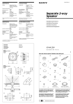
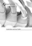
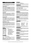
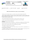
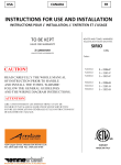
SPECIFIC VEHICLE ALARM FITTING INSTRUCTIONS
REV. 00
www.cobra.it
MAKE
DAEWOO
MOD.
NUBIRA
YEAR
98 →
PETROL
DIESEL
X
ALARM/SIREN
POSITION
Position the compact alarms and the sirens in the engine compartment near the
left lateral headlamp. Position the modular systems and the modules under the
dashboard, drivers side.
POWER SUPPLY
+ 30: connect to the 2,5mm RED wire located at the rear of the left lateral frame,
drivers side.
- 31: connect with an eyelet cable terminal to one of the fastening bolt of the
dashboard.
DIRECTION INDICATORS
Connect to the 1 mm BLUE and LIGHT BLUE wires located in the wiring
harness and coming out of the 22 way yellow connector located on the support of
the connector holder, above the fuse box behind the left lateral frame, drivers
side.
ELECTRIC WINDOWS
Positive control signal
Front window, driver’s side:
cut the BLUE wire directly outgoing from the switch of the window to the inner
drivers side door.
Front window, passenger’s side:
2
cut the 1,5 mm LIGHT BLUE wire.
Rear window, driver’s side:
2
cut the 1,5 mm BROWN wire.
Rear window, passenger’s side:
2
cut the 1,5 mm GREEN wire located in the wiring harness coming out of the
drivers side door.
CENTRAL DOORS LOCKING
Negative control signal
Connect to the LIGHT BLUE wires with WHITE reference located at the position
nr. 7 (lock) and the YELLOW at the position nr. 1 (unlock), in the 9 way white
connector of the central door locking unit located at the rear of the left lateral
frame, drivers side.
Note: for the vehicles without original key less entry, please refer to
diagram nr. 42 for the serie Bridge antithefts or refer to diagram nr.42A for
serie 3100 antithefts.
IMMOBILISATION POINT
The vehicle has an original equipment immobiliser that may be enabled
immediately when the switchboard is switched off.
BONNET SWITCH
Install an additional switch on the front headlamp support plate.
DOORS SWITCH
Connect to the 0,5 mm WHITE wire located in the wiring harness coming out of
the 16 way white connector, on the support of the connector holder, above the
fuse box behind the left lateral frame, drivers side.
BOOT SWITCH
Connect to the 0,5 mm PINK wire with BLACK reference located in the wiring
harness and coming out of the 16 way white connector located on the support
mentioned above.
2
2
2
2
Note: This information is not binding, therefore it must be considered only an example for installation purposes that must be executed
as per the instructions given on the product installation manual.
danub98gbb.doc
SPECIFIC VEHICLE ALARM FITTING INSTRUCTIONS
REV. 00
www.cobra.it
FITTING DIAGRAM N°42
Serie BRIDGE antitheft
ORANGE/VIOLET
White connector coming out of the central
doors locking unit.
VIOLET
ORANGE
3 4
1 2
5 6 7 8 9
Negative control signal
For the versions without original radio control the positions Nr. 1 and Nr. 7 of the
white connector of the central doors closing are free, so insert suitable fastons.
Note: This information is not binding, therefore it must be considered only an example for installation purposes that must be executed
as per the instructions given on the product installation manual.
danub98gbb.doc
SPECIFIC VEHICLE ALARM FITTING INSTRUCTIONS
REV. 00
www.cobra.it
FITTING DIAGRAM N°42A
Serie 3100 antitheft
ORANGE/WHITE
VIOLET/WHITE
White connector coming out of the central
doors locking unit.
VIOLET
ORANGE
3 4
1 2
5 6 7 8 9
Negative control signal
For the versions without original radio control the positions Nr. 1 and Nr. 7 of the
white connector of the central doors locking are free, so insert suitable fastons.
Note: This information is not binding, therefore it must be considered only an example for installation purposes that must be executed
as per the instructions given on the product installation manual.
danub98gbb.doc