1
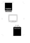
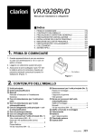
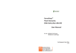
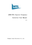
VMA633
6.5 INCH WIDE LCD MONITOR
VMA633
6.5” WIDE ACTIVE MARTIX TFT
COLOUR LCD MONITOR
OWNER’S MANUAL
INSTALLATION GUIDE
OWNER’S MANUAL
WARNING!
THE CLARION VMA633 LCD MONITOR IS DESIGNED FOR NAVIGATION PURPOSE AND REAR
SEAT PASSENGER VIEWING ONLY.
THIS PRODUCT IS NOT INTENDED FOR VIEWING MOVIES BY THE DRIVER WHILE THE VEHICLE
IS IN MOTION. SUCH USE MAY DISTRACT THE DRIVER OR INTERFERE WITH THE DRIVER’S
SAFE OPERATION OF THE VEHICLE AND MAY RESULT IN SERIOUS INJURY OR DEATH. SUCH
USE MAY ALSO VIOLATE STATE LAW. CLARION DISCLAIMS ANY LIABILITY FOR ANY BODILY
INJURY, INCLUDING FATALITIES, OR PROPERTY DAMAGE THAT MAY RESULT FROM ANY
IMPROPER OR UNINTENDED USES OF THIS PRODUCT.
INTRODUCTION:
The VMA633 is a TFT active matrix colour LCD monitor that delivers a striking picture
with superior image resolution. The Clarion VMA633 is a full-feature 6.5” LCD Colour Monitor
and has the following topics:
●
6.5” wide-screen colour LCD panel.
●
A bright vibrant clear screen.
●
Video composite & RGB 8-pin DIN Style inputs
●
Built-in speaker for navigation announcements
●
Universal mount for easy installation in different car types
ABOUT THIS MANUAL AND WARRANTY:
To start enjoying your new Clarion VMA633 monitor, please read the instructions listed in
this manual. Keep all instructions for future reference. Please fill out and send in the
enclosed warranty card to protect your purchase and aid in warranty service. Also, save
INTRODUCTION
your original sales receipt as proof of purchase.
TABLE OF CONTENTS:
1
INTRODUCTION, ABOUT THIS MANUAL & TABLE OF CONTENTS
1
PRECAUTIONS & DESCRIPTION OF BUTTONS AND CONNECTORS
2
DESCRIPTION OF PICTURE ADJUSTMENT
3
CARE AND MAINTENANCE
3
WIRING PRECAUTIONS
3
DESCRIPTION OF INSTALLATION
4
TROUBLESHOOTING
5
SPECIFICATIONS
5
VMA633 6.5” TFT LCD Monitor
PRECAUTIONS:
●
This monitor is intended for use in DC 12V, negative ground vehicles.
●
Do not operate the monitor in ways other than described in this guide, doing so may cause
damage and void the warranty.
●
Be careful not to run down the car’s battery while using a multimedia system with the engine
stopped. Doing so may damage the vehicle’s battery or the multimedia system.
●
Do not disassemble or modify monitor. Doing so may damage it and void the warranty.
●
Keep moisture away from the set. Water and humidity may damage the internal circuitry.
●
Do not let the monitor become overheated. If the temperature inside the vehicle is high or the
monitor has been exposed to direct sunlight, lower the monitor’s temperature before use. (The
liquid crystal panel operates within a temperature range of –1~45°C (30~113°F).
●
In extremely cold temperature, the movement of the picture may slow and the picture may
become dark. The monitor will work normally once the temperature increase to its normal
operation range.
●
Small black or shiny dots may been see inside the liquid crystal panel. These are normal when
manufacturing liquid crystal products.
DESCRIPTION OF BUTTON AND CONNECTORS:
VMA633
6.5 INCH WIDE LCD MONITOR
1
2
3
4
5
6
D ESCRIPTION B UTTONS
7
8
9
10
11
12
13
1. Power Button
2. Dimmer Sensor
3. Remote Sensor
4. Picture Controls
5. Wide Mode Controls
6. Source Controls
7. Video Composite Input
8. 2-Pin Molex Power Connector
9. IR Serial Remote OUT
10. 8-Pin RGB input DIN cable
11.Speaker (White w.Black line)
12.Speaker + (White)
13.Dimmer Lead
(Orange)
2
OWNER’S MANUAL
DESCRIPTION OF PICTURE ADJUSTMENT:
●
Press the PICTURE SELECT button several times, the screen will display the picture control
Bar in the following order sequentially.
(BLANK)àBRIGHTNESSàCONTRASTàCOLOURàTINTàDIMMERàMEM RESET─
●
Before the display disappears, use the PICTURE SELECT UP (VOLUME UP) button or PICTURE
SELECT DOWN (VOLUME DOWN) button, to adjust the picture quality.
COLOUR
←
●
●
→
DOWN
UP
Press the WIDE/NORMAL button, the screen will display 16:9 or 4:3 picture.
DIMMER:Press UP、DOWN or Brightness to choose seven different sets.
Auto
Brightness automatically
DASHBOARD Controlled by Dashboard illumination
●
MEM RESET:Press UP or DOWN, all sets return the initial value.
CARE AND MAINTENANCE:
Cleaning the Cabinet:
●
●
Use a soft, dry cloth to gently wipe off any dirt.
Do not use benzene, thinner, car cleaner, etc., as these substances may damage the
cabinet or cause the point to peel.
Cleaning the LCD Panel:
●
●
Use a soft, dry cloth to gently wipe off any dust.
The surface is easily scratched, do not rub it with hard objects.
PICTURE ADJUSTMENT
WIRING PRECAUTIONS:
Read all wiring precautions. If you are not sure of the connections, contact your
authorized Clarion dealer.
1.Disconnect the negative (-) lead from the vehicle’s battery before making any
connections.
2.When creating passage holes through metal or plastic, use grommets to
Eliminate any sharp edges created during drilling. This will protect power or
video wires from nicks or damaged causing a possible short circle or failure.
3.When connecting the ground lead, fasten the ground lead (black) securely to
a clean metal plate on the vehicle. Use sandpaper to remote any paint from the
surface where the ground terminal is attached.
DESCRIPTION OF INSTALLATION:
Now the VMA633 is useable with including mounting bracket. The VMA633 monitor
will accept a video signal from any video source with composite video output.
The Infrared
(IR) sensor will work with a Clarion NAX9500E using the CCE-001 adapter and IR
extension cable, which are provided.
3
VMA633 6.5” TFT LCD Monitor
1.
Look over the vehicle for a monitor location. Each vehicle is different and locations
will vary. Make sure the monitor will not interfere with the driver’s safe operation of
vehicle.
2.
Once a location has been determined, run the 3.5 mm IR extension, Video Composite
and power Molex connector into the monitor’s mounting location.
3.
Plug main cable into the monitor.
4.
Run the IR extension, video, and power cables to their respective destinations.
6.5 INCH WIDE LCD MONITOR
1
2
3
4
5
6
7
8
RED
GREEN
BLUE
C-SYNC
NOT CONNECTED
NOT CONNECTED
NOT CONNECTED
NOT CONNECTED
4
2
1
6
8
VMA633
5
3
7
RGB Input DIN Configuration
from Composite
Video Source
Video
Composite In
To lgnition
Fuse
+12V
Ground(To Chassis)
To Remote Onput
IR Remote Output
from RGB
Video Source
from RGB Output of
NAX9500E
RGB Input DIN Connector
I NSTALLATION
speaker(-)
speaker(+)
Dimmer Lead
NAX
*
NOTE:
C
*These CCE-001 adapt IR of NAX
C
VS718
and/or VS718 to VMA633! Never use
E
Video Out
-
IR connection without CCE-001!
0
4
0
1
OWNER’S MANUAL
TROUBLESHOOTING:
Symptom
Cause
Solution
System does not
work
Fuse is blown.
Replace external fuse with the same
value.
Check the wire connections and
Connect it properly.
Check that the brightness is properly adjusted, if not adjust it properly.
This may happen if the temperature
in the vehicle is below –1°C (30°F) or
above 45°C (113°F). Check again
when the temperature is between
-1°C (30°F) and 45°C (113°F)
The screen dark.
Power wires are not
connected.
The brightness is adjusted
too low.
Usage conditions are poor.
SPECIFICATION:
GENERAL SPECIFICATIONS:
Power Requirement:
Power Consumption:
Weight
Dimensions (w x h x d):
Included Parts
+12 Volts DC (9-16 Volts DC)
9 watts, Power On
0.8 amps (800mA)
0.5 kg (1.1 lb)
167 x 121 x 29 mm (6-1/2 x 4-7/10 x 1-3/10 in.)
LCD Monitor
3.5 mm Male to Male IR extension cable (5m)
2-pin Molex Power connector
CCE-001 IR adapter for NAX9500E and/or VS718
Mounting bracket
Speaker extension cable (5m)
MONITOR SPECIFICATIONS:
TROUBLE SHOOTING
Display Type:
Screen Size:
Pixels:
Screen Resolution:
Video Input Level(RCA)
RGB Input Level
5
Colour TFT Active Matrix LCD
6.5” (Panel Dimensions 144.4 x 80.3 mm)
1200 x 234
280,800 dots
1.0 volts peak to peak, NTSC
0.75 volts peak to peak, TTL