1
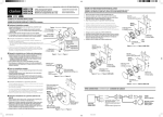
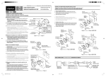
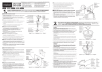
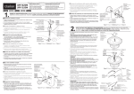
Printed in China / Imprimé en Chine / Impreso en China 2003/8 (D• C/GPE)
SRS1725
SRS1625
SRS1325
English
Français
SE-751A/SE-752A/SE-753A
2-Way Component System
Système de haut-parleurs à 2 voies
Sistema de componentes de 2 vías
Installation Manual
Manuel d’installation
Manual de instalación
1. Using the template, open holes for the speaker and for the screws.
Español
2. Install the bracket on the door trim. (Figure 1)
3. Attach the supplied U-type rubber onto the punching net and install it
onto the grille. (Figure 4).
Door trim
Garniture de porte
Panel de adorno de la puerta
1. A l’aide du modèle, percez des trous pour le haut-parleur et les vis.
2. Posez les écrous fendus sur les trous percés dans la garniture de
porte, puis installez la rondelle de haut-parleur avec les vis à tôle.
(Figure 4)
Bracket
Support
Soporte
U-type rubber
Caoutchouc en forme de “U”
Caucho de tipo U
3. Attachez le caoutchouc en forme de “U” sur la grille de protection et
installez l’ensemble sur la grille. (Figure 4)
2. Fixez le support sur la garniture de porte. (Figure 1)
3. Appuyez sur le haut-parleur contre le support et tournez pour le
fixer.
Speaker
Haut-parleur
Altavoz
*For the SRS1625 model, mount grille after the installation of the
speaker.
3. Press and turn the speaker onto the bracket to fasten it.
1. Enlevez la garniture de porte et, à l’aide du modèle 1, percez
des trous pour les vis et les fils de haut-parleur.
Door trim
Garniture de porte
Panel de adorno de la puerta
2. Install the speed nuts in the screw holes in the door trim, then use the
mounting screws to install the speaker grille. (Figure 4)
EXAMPLE OF TWEETER INSTALLATION
EXEMPLE D’INSTALLATION D’UN HAUT-PARLEUR D’AIGU
EJEMPLO DE INSTALACIÓN DEL ALTAVOZ DE AGUDOS
1. Remove the door trim, then use template 1 and open holes for
the screws and speaker leads.
EXAMPLE OF MID-RANGE/WOOFER INSTALLATION
EXEMPLE D’INSTALLATION D’UN HAUT-PARLEUR DE MÉDIUM-GRAVE
EJEMPLO DE INSTALACIÓN DE ALTAVOZ DE GAMA MEDIA/GRAVES
2–Mounting screws
2–Vis à tôle
2–Tornillos de montaje
2–Speed nuts
2–Ecrous fendus
2–Tuercas rápidas
1. Quite el panel de adorno de la puerta, y después utilice la plantilla 1 para taladrar orificios para los tornillos y el cable del
altavoz.
*Pour le modèle SRS1625, montez la grille après avoir installer le
haut-parleur.
3. Fije el cauchop de tipo U en la red e inatálela en la rejilla.
3. Presione y gire el altavoz en el soporte para fijarlo.
Grille
Grille
Rejilla
1. Utilizando la plantilla, taladre orificios para el altavoz y para los tornillos.
2. Instale las tuercas rápidas en los orificios para los tornillos del panel
de adorno de la puerta, y después utilice los tornillos de montaje para
instalar la rejilla del altavoz. (Figura 4)
2. Instale el soporte en el panel de adorno de la puerta. (Figura 1)
4–Speed nuts
4–Ecrous fendus
4–Tuercas rápidas
(Figura 4)
Speaker
Haut-parleur
Altavoz
4–Mounting screws
4–Vis à tôle
4–Tornillos de montaje
Punching net
Grille de protection
Red
Figure 4 / Figure 4 / Figura 4
*Con respecto al modelo SRS1625, monte la rejilla después de haber
instalado el altavoz.
Figure 1 / Figure 1 / Figura 1
1. Insert the two lever arms fully into the central holes of the flushmount spacer. Use the machine screw to secure the lever arms.
2. After installing the lever arm, attach the bracket onto the flushmount spacer using the machine screws.
Door trim
Garniture de porte
Panel de adorno de la puerta
Bracket
Support
Soporte
2–Machine screw
2–Vis à métaux
2–Tornillo para metal
3. Attach the flush-mount spacer onto the door trim. After installation is complete, screw in the speaker until it is fixed into position.
Flush-mount spacer
Monture encastrable
Separador para montaje a ras
Speaker
Haut-parleur
Altavoz
Speaker
Haut-parleur
Altavoz
U-type rubber
Caoutchouc en forme de “U”
Caucho de tipo U
2–Lever arms
2–Leviers
2–Brazos de palanca
Machine screw
Vis à métaux
Tornillo para metal
1. Insérez les deux leviers à fond dans les orifices centraux de la
monture encastrable avec support. Fixez les leviers avec les vis
à métaux.
3–Speed nuts
3–Ecrous fendus
3–Tuercas rápidas
Figure 2 / Figure 2/ Figura 2
2. Après avoir installé le bras du levier, fixez l’étrier sur l’entretoise
de montage encastré à l’aide de vis à métaux.
3. Fixez l’entretoise de montage encastré sur la garniture de porte.
Lorsque l’installation est terminée, vissez le haut-parleur à fond.
1. Inserte completamente los dos brazos de palancas en los orificios centrales del separador para montaje a ras. Para asegurar
los brazos de palancas, utilice los tornillos de montaje.
2. Después de haber instalado el brazo de palanca, fije el soporte
en el separador para montaje a ras utilizando los tornillos para
montaje.
Door trim
Garniture de porte
Panel de adorno de la puerta
Grille
Grille
Rejilla
3–Mounting screws
3–Vis à tôle
3–Tornillos de montaje
Grille
Grille
Rejilla
Flush-mount spacer ass’y
Monture encastrable
avec support
Conjunto del separador
para montaje a ras
4–Speed nuts
4–Ecrous fendus
4–Tuercas rápidas
Punching net
Grille de protection
Red
Figure 5 / Figure 5 / Figura 5
4–Mounting screws
4–Vis à tôle
4–Tornillos de montaje
Figure 6 / Figure 6 / Figura 6
WIRE CONNECTIONS / CONNECTIQUE / CONEXIÓN DE CABLES
3. Fije el separador para montaje a ras en el adorno de la puerta.
Una vez finalizada la la instalación, atornille el altavoz hasta que
quede fijado en su posición.
(+)
(+)
(–)
(+)
Door trim
Garniture de porte
Panel de adorno
de la puerta
Speaker
Haut-parleur
Altavoz
Figure 3 / Figure 3 / Figura 3
(–)
Center Unit
Appareil pilote
Unidad central
(+)
R
Tweeter
Aigu
Altavoz de agudos
(–)
(–)
L
* Connect the L side in the same way as
for the R side.
* Raccorder le côté L (gauche) de la
même manière que le côté R (droit).
* Conecte el lado L igual que el R.
(+)
Mid-range / Woofer
Médium-Grave
Altavoz de gama media / graves
(–)
Gedruckt in China / Stampato in Cina 2003/8 (D• C/GPE)
SRS1725
SRS1625
SRS1325
Deutsch
SE-751A/SE-752A/SE-753A
2-Weg-Komponentensystem
Sistema a componenti a 2 vie
Installationsanleitung
Manuale d’lstruzioni
1. Using the template, open holes for the speaker and for the screws.
Italiano
2. Install the speed nuts in the screw holes in the door trim, then use the
mounting screws to install the speaker grille. (Figure 4)
BEISPIEL FÜR EINBAU EINES HOCHTONLAUTSPRECHERS
ESEMPIO DI INSTALLAZIONE DEL TWEETER
3. Für Befestigung den Lautsprecher auf die Befestigung drücken
und drehen.
1. Rimuovere la copertura della portiera, poi usare la maschera 1
per aprire fori per le viti e i cavi diffusore.
Türleiste
Copertura della portiera
3. Attach the supplied U-type rubber onto the punching net and install it
onto the grille. (Figure 4).
Lautsprecher
Diffusore
∗ For the SRS1625 model, mount grille after the installation of the
speaker.
1. Die Türleiste entfernen und dann mittels der Schablone 1 die
Löcher für die Schrauben und Lautsprecherleitungen öffnen.
2. Die Befestigung an der Türleiste anbringen. (Abbildung 1)
BEISPIEL FÜR EINBAU EINES MITTELBEREICH/TIEFTONLAUTSPRECHERS
ESEMPIO DI INSTALLAZONE DEL MEDIAGAMMA/WOOFER
1. Usando la maschera, aprire fori per il diffusore e per le viti.
Türleiste
Copertura della portiera
2. Installare i dadi rapidi nei fori vite nella copertura della portiera, poi
usare le viti di montaggio per installare la griglia diffusore. (Figura 4)
U-Typ-Gummi
Gomma di tipo U
3. Applicare la gomma di tipo U in dotazione alla retina di foratura e
installarla sula griglia. (Figura 4)
Befestigung
Staffa
4-Schnellmuttern
4 dadi rapidi
∗ Per il modello SRS1625, montare la griglia dopo aver installato il diffusore.
2. Installare la staffa sulla copertura della portiera.
3. Premere e ruotare il diffusore sulla staffa per fissarlo.
2-Befestigungschrauben
2 viti di montaggio
2-Schnellmuttern
2 dadi rapidi
Gitter
Griglia
4-Befestigungschrauben
4 viti di montaggio
Stanznetz
Retina di foratura
Abbildung 4 / Figura 4
Lautsprecher
Diffusore
Abbildung 1 / Figura 1
1. Die beiden Hebelarme vollständig in die mittleren Löcher des
eingelassenen Abstandhalters einführen. Die Hebelarme mit
der Maschinenschraube sichern.
2. Nach Einbau der Hebelarme, mit den Maschinenschrauben die
Befestigung beim eingelassenen Abstandhalter anbringen.
Türleiste
Copertura della portiera
Türleiste
Copertura della portiera
Befestigung
Staffa
Lautsprecher
Diffusore
2-Maschinenschraube
2 viti da macchina
Eingelassener Abstandhalter
Spaziatore per montaggio incassato
3. Den eingelassenen Abstandhalter auf der Türleiste anbringen.
Nach Beendigung des Einbaus, den Lautsprecher einschrauben, bis er fest einsitzt.
Lautsprecher
Diffusore
2-Hebelarme
2 bracci leva
U-Typ-Gummi
Gomma di tipo U
Maschinenschraube
viti da macchina
1. Inserire i due bracci leva a fondo nei fori centrali dello spaziatore
per montaggio incassato. Usare la vite da macchina per assicurare i bracci leva.
4-Schnellmuttern
4 dadi rapidi
3-Schnellmuttern
3 dadi rapidi
Abbildung 2 / Figura 2
2. Dopo aver installato i bracci leva, applicare la staffa allo spaziatore per montaggio incassato usando le viti da macchina.
Gitter
Griglia
3. Applicare lo spaziatore per montaggio incassato alla copertura
della portiera. Una volta completata l’installazione, avvitare il diffusore fino a che viene fissato in posizione.
3-Befestigungschrauben
3 viti di montaggio
Gitter
Griglia
Stanznetz
Retina di foratura
Eingelassener
Abstandhalteraufbau
Insieme dello spaziatore
per montaggio incassato
Abbildung 5 / Figura 5
4-Befestigungschrauben
4 viti di montaggio
Abbildung 6 / Figura 6
VERDRAHTUNG / COLLEGAMENTO DEI CAVI
(+)
(+)
(–)
(+)
Türleiste
Copertura della portiera
(–)
Lautsprecher
Diffusore
Mitteneinheit
Unità centrale
Abbildung 3 / Figura 3
(+)
R
Hochtonlautsprecher
Tweeter
(–)
(–)
L
* Die L-Seite (links) genauso wie doe RSeite (rechts) verbinden.
* Collegare il lato L nello stesso modo
del lato R.
(+)
Mittelbereich/Tieftonlautsprecher
Mediagamma/woofer
(–)