1
Printed in Malaysia / !"# / W=
!"
284-9857-00
Installation/Wire Connection Guide
=L= !
=L=
=
=L=
=L=
==
English
1. BEFORE STARTING / 1. !"#$%&' 12 V 2. Read these instructions carefully.
2. !"#$%&'
3. Be sure to disconnect the battery “-” terminal
before starting. This is to prevent short circuits
during installation (Figure 1).
3. !"#$%&'()- I=
!"#$%&'( 1
!"#$%&'(")*+,-./01234✽
!"#!$%&' 7
!"#$
Bend the stopper following the procedures below when this source
unit is installed to the TOYOTA, NISSAN and other ISO/DIN equipped
vehicles.
1. = = = 12 V ==
=== !"K
2. =
!"#====
!
!"#$%&'()*+
= =
!"
!"#$%&'(#)*+,-./0(#12345678
!"#
!"=
==
= = != !==I=E✽F= =
= = !"= !"#K=E=7F
= = != !===I==
== == = !"#K
!"#$%"&'()*+,-."/ ISO/DIN !"#
!"#$%&'()*
= !"= I=I==ISO/DIN=
=== == != !"#K
1. NK=
!"#$%&'()*+=56
!"=
!=
=
= =
!"#K=E=5I=6F
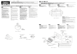
1. Bend the stopper from the source unit. (Figure 5, 6)
BEFORE BEND / 3. !== !"- !=
= !"#K=== !"=
!K=E=1F
/ !
!==
AFTER BEND / STOPPER / / =
/ Car battery
!
=
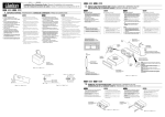
2. CAUTIONS ON INSTALLATION / !"#$% / = !
1. Prepare all articles necessary for installing the source unit before
starting.
1. 2. Install the unit within 30° of the horizontal plane (Figure 2).
3. 3. If you have to do any work on the car body, such as drilling holes,
consult your car dealer beforehand.
4. !"#$%&'()* +,$%-./012*34 3
SOURCE UNIT / ! / !
!"#$%&'()*(+,-./0123
1. !==
= !K
2. !"#$%&'()*+,- 30° !" 2
3. ==== =
= !"#K
Max. 30°
30°
30°
= =I== =
2. Secure the mounting brackets to the chassis as shown in Figure 7.
Holes are pre-tapped for TOYOTA and NISSAN vehicles;
modification, such as drilling new holes, of the mounting brackets
may be required for other models.
3. Wire as shown in Section 8.
Figure 6 / 6 / 6
2. 7 !"#$%&'()*+,-./01234567
!"#$%&'()*+,-.
3. 8 !"#$
/0123
4. %&'/01'2
!" / !
!== !
1. Place the universal mounting bracket into the instrument panel,
use a screwdriver to bend each stopper of the universal mounting
bracket inward, then secure the stopper as shown in Figure 4.
1. !"#$%&'()*+ ,-. !"#$/01
!"#$%&'() 4 !"#$%
2. Wire as shown in Section 8.
3. !"#$%&!'()*+,-./
4. !"#$%&'()*+,-
3. Insert the source unit into the universal mounting bracket until it
locks.
!"#
2. 8 !"#$
Notes:
1) Some car models require special mounting kits for proper
installation. Consult your Clarion dealer for details.
1) !"#$%&'()*+,-.&/012345
Clarion !"#
2) Fasten the front stopper securely to prevent the source unit
from coming loose.
2) !"#$%&'()*"+
Hole
==
!"#K
3. !"== ===
!K
!==
4. =
!=
!=
Center Panel (Note 1)
!"=1
=E=1F
!===
Figure 7 / 7 / 7
!K
W
1) == !"= = == ==
= !"K= = Clarion != !"
K
2) = !== = !"= ==
= !K
✽: The parts and screws with this mark are used to install radio or
included in the installation kit.
★: The screws with this mark are originally attached to the vehicle.
✽: !"#$%&'()*+,-./012*+3456
★: !"#$%&'()"*
1: !"#$%&'()*+,-./01234567
Note 1: In some cases, the center panel may require some modification (trimming, filling, etc.).
2: !"#$%&'()*!+,-./012345678
!
✽: = = = = =
== = != !K
★: = = = =
!=
1: = != !==
EI== =F
Bottom
Hexagonal bolt
!
=
Strap
✽ This part is not provided in some models.
✽ !"#$%&"'()
✽ = !"== = !=
Source Unit
!
!
Outer escutcheon side view
!"#
= ==
!=
=
!K
!"# / !
!== !
1. When removing the source unit, disassemble it in the reverse of
the order in Section “3. INSTALLING THE SOURCE UNIT”.
1. !"#$%&'()=3 3.= !"#$%&'(
!
1. !"= =I=3.= != !"#=
= != !"= !"#K
2. Press the outer escutcheon upward and remove it (Figure 8).
2. !"#$%&'()* 8
2. =
3. Insert and lock the hook plates (Figure 9).
3. !"#$%&'( 9
3. ==
=
4. Pull the hook plates to remove the source unit.
4. 4. ==
!=
!"#$%&'()*
!=
!==
Note:
Before attaching the universal mounting bracket, slightly bend
the spring toward the inside with your fingers and attach it to the
side of car.
!"#$%&'(!)*+,-./012'+3
!"#
W
== != !=I= !"= !=
= !== =I=== !"#K
Figure 8 / 8 / 8
2/12/03, 15:23
!"#K=E=8F
!"K=E=9F
!"=
2–Hook plates
2 !
==2=
Outer escutcheon
=
Figure 4 / 4 / 4
1
!=
4. REMOVAL OF THE SOURCE UNIT / Universal mounting bracket
!"#
==
Stoppers
Outer escutcheon
=
=
!"=
!
!K
!K
2: = !== = I= = = =
= !"= = !K
Top
Installation direction
!
=
!=
Instrument panel
Stoppers
Screwdriver
!
!==
Pocket
!"=
English
Hole
!=
= =I=
Note 2 / 2 / 2
Note 2: If a hook on the installation bracket interferes with the unit,
bend and flatten it with a nipper or a similar tool.
• Console opening dimensions
• !"#$
• ==
==
!"#K
4–Hexagonal screw ✽ (M5 x 8)
4 !"=✽M5 x 8
==✽=EM5 x 8F=4 1. == != == !"I= !"=
=== !== != != !"#K=
=I= 4 = = = !== !"
K
2. 8 =
4. Mount the outer escutcheon so that all the hooks are locked.
==
Dashboard
■ ==
■ 3. 8 =
Source Unit
!
!
■ Universal Mount
2. =7 = = == != = !"#K
=== !== == = !K
= === ==== != !
= !K
4. !=
K
Mounting bracket ✽
(1 pair for the left and right sides)
!=✽
!"#$%&'
= ✽
E != !"= =
F
Damage
Figure 3 / 3 / 3
3. INSTALLING THE SOURCE UNIT / !"#$%&'()*+,-.
4. Secure the unit in the dashboard, and then reassemble the dashboard and the center panel.
Chassis / / Max. 5/6” (8 mm)
5/6” (8 mm)
5/6” (8 mm)
Figure 2 / 2 / 2
Figure 5 / 5 / 5
!"= == =
4. = = = = !"#K== =
= = == !K=E 3F
Chassis / / !"=
2. !" 30° = = !"#K=E 2F
!"#$%&'()*+,-.,/01#234567
4. Use the enclosed screws for installation. Using other screws can
cause damage (Figure 3).
(IM) DB246
!"#$K
!K
Figure 1 / 1 / 1
English
This unit is designed for fixed installation in the dashboard.
If the vehicle is not equipped with a factory-installed radio, obtain an
installation kit to install the source unit in the following procedure.
! / !
!==
1. This set is exclusively for use in cars with a
negative ground, 12 V power supply.
English
■ !
!"#$%&'( ISO/DIN If the vehicle is equipped with a factory-installed radio, install the source
unit with the parts and screws marked (✽) (Figure 7).
■ ==
E I=
I=
F
I=
I=
I=
==ISO/DIN== =
F
■ Fixed Mount
(TOYOTA, NISSAN and other ISO/DIN equipped
vehicles)
Figure 9 / 9 / 9
!"#K
English
English
5. CAUTIONS ON WIRING / 8. WIRE CONNECTIONS / / =
!"#$% / = = !
1. Be sure to turn the power off when wiring.
1. !"#$%&'
1. =
2. Be particularly careful where you route the wires.
Keep them well away from the engine, exhaust pipe, etc. Heat may
damage the wires.
2. !"#$%&'
!"#$%&'()*+,-./01
2. = != == !"#K
I== = == !=
!== !K
+
3. !"#$%&'()*+,-./
!"#$%&'()*+,-./0123456+,-7
3. If the fuse should blow, check that the wiring is correct.
If it is, replace the fuse with a new one with the same amperage
rating as the original one.
4. !"#$%&'()*+,-.$/01 !"2)34
!" 10
✽ !"#$%&'()*+*,-./01%23456
!"#$%
4. To replace the fuse, open the lock on the source unit side, remove
the old fuse and insert the new one. (Figure 10)
✽ There are various types of fuse cases. Do not let the battery
side terminal touch other metal parts.
Example 1
1
=N
Example 2
2
=2
Fuse
==
=
= !K
!K==
■ Rear Layout
■ ■ 3. = !=I== = != !"#K
= = =I= = == = =
== = !"#K
4. =
=
✽ =
=
!"I= != == !"==
!== = !"#K=E=10F
!= = !K= == =
== = !K
Example 3
3
=3
Fuse case
!
=
Fuse
Antenna
Fuse
Fuse case
!
=
Figure 10 / 10 / 10
English
Fuse case
!
=
6. GENERAL CAUTIONS / !"# / == !
1. Do not open the case. There are no user serviceable parts inside.
If you drop anything into the unit during installation, consult your
dealer or an authorized CLARION service center.
1. !"#$%&'()*+,-./0&1$2345678
!"#$%&'()*+,- CLARION !"#$
1. !== !K= != != ===
== !K==== !== !
==CLARION== = !"#K
2. Use a soft, dry cloth to clean the case. Never use hard cloth, thinner,
benzen, alcohol, etc. For tough dirt, apply a little cold or warm water to a soft cloth and wipe off the dirt gentry.
2. !"#$%&'()*+,#-./0-123456(
!"#$%&'()*+,-./-00123
2. !== = = != !"#K==
I=I=I= === != !K=
= = = = == != =
== !K
IMPORTANT:
Improper installation may cause damage to your unit or car. If you
do not have the appropriate experience, consult a qualified installer.
Cutting chassis wire leads voids the warranty.
English
!"#$%&'()*+,-./0123456789
!"#$%&'()*+,-./012&
W
W
= != = = == !K= =
I= == !"#$= !"#K==
= == = != !K
Front Right
!
==
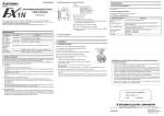
4-Speaker system
4 !"
4 =
Rear Right
!
==
+ Purple
+ + – Purple/Black
– L
– L
Rear Left
!
==
7. SAMPLE SYSTEMS / ! / =
1
2
3
4
5
6
1
4
Right
3
1
2
3
4
5
6
!
RCA !"#$%
2 !"#$
!"
!"
!"#
2-Speaker system
2 !"
2 =
6
1
2
3
4
5
6
– Gray/Black
– L
– L
+ Purple
+ + – Purple/Black
– L
– L
No used.
Insulate each wire.
!
!"#$
==
KK
= = K
!
RCA = =E=F
2 = !
=
=
!
Rear Right
!
==
Orange/White wire (Illumination lead)
L !"# $
L=E=F
Yellow wire (Memory back-up lead)
!"#$%& '
=E ==F
+ Green
+ + Fuse (15 A)
!15 A
=E15 AF
Connect directly to battery.
!"#$
!== K
Red wire (Power lead)
!"# $
==E=F
Accessory + 12 V
+ 12 V
! + 12 V
+ Gray
+ + Left
2
Red
– White/Black
– L
– L
or
Source Unit
RCA Extension Cables (sold separately)
2-Channel Power Amplifier
Front Speakers
Rear Speakers
Sub-woofers
+ White
+ + – Green/Black
– L
– L
English
5
– Gray/Black
– L
– L
Rear Left
!
==
16-pin Connector Extension Lead
(attached to the source unit)
16 !"#$%
!"#$%&
16 = =
==
E !"= F
+ Gray
+ + Front Left
!
==
16-pin connector
16 !
16 =
White
+ White
+ + Blue/White wire (Power Antenna turn-on lead)
L !"#$ %& '
L=E= = F
Connect to remote turn-on lead of Power Antenna. (0.5 A current max.)
!"#$%&'()$*+,-!.=0.5 A
= !==== K=E==0.5 AF
– White/Black
– L
– L
+ Green
+ + – Green/Black
– L
– L
Black wire (Ground lead)
!" #
==E=F
Connect to vehicle chassis ground.
!"#$%&'
== = K
Clarion Co., Ltd.
(IM) DB246
2
1/12/03, 9:19 PM