1
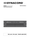
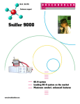
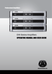
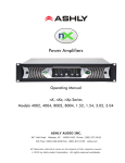
Professional Power Amplifier
POWER
ON
PROTECT
OFF
SIGNAL
CLIP
PPX900
CHANNEL 1
CHANNEL 2
PPX Series
Professional Power Amplifier
Before attempting to connect,operate or adjust this product,please read these instructions completely
Rev: 2.0-CITRONIC-PPX 11/2010
POWER
ON
PROTECT
OFF
SIGNAL
CLIP
PPX900
CHANNEL 1
CHANNEL 2
Co ngratul ations f or choo sing CITRONIC PPX Se ries profession al power ampli fier. You purchased one of the fi nest
stereo am plifiers o n the m arket to day. Thi s unit was deve loped u sing the expert ise of pr ofessional soun d engin eers
an d working musicians. You will f ind that your new CITRONIC PP X Serie s amplifier has superi or performance and
gr eater fle xibility t han any other a mplifiers in its p rice range. Plea se read this ma nual ca refully to get th e most o u t of
your new unit.
Offering top power, superior performance and full professional operating features in a r oadworthy compact chassis, the
PPX Series are perfect for even the most demanding sound reinforcement installation and touring applications.
The operating amplifier instruction in this manual are for all the PPX Series professional power amplifiers. The operation
and functions of these units are the same, except as noted.
. Full oper ating features: detent volume contr ol s; parallel balanced XLR a nd 1/4" TRS inputs; st er eo ( dual channel), par al lelinput , or br idged mo no operating modes with selector swit ch;
I ndependent user defeatable c li p li miter s (compr ess or ) 3
sel ectable i nput se nsitiviti es, ground lift switch, bi nding p ost
( banana plug) and s peakon out puts.
. Full safety/r e l iabi lity features: 2 dual speed f ans f or cooling;
sof t start tur n on, no ise-fr ee on-off; independent DC and thermal
overload protection on ea ch chan nel ; shor t ci rcuit and speaker
protection; built-in current limi ter.
. Front panel led i ndicators: Active, Signal, Limi t and pr ot ecti on
Table of contents
FEATURES ............................................................... 1
WARNING ................................................................. 2
. Roadwor thy, rugge d steel chassis (2U)
. Modu la r constr uct ion f or easy ser vicing
For your records
Date of Purchase _____ _________________________
Dealer 's Name __________________________ ______
City _________________________________________
INSTALLATION........................................................ 2
State _____ _____________ Zip __________________
FRONT & RE AR PANEL CONNECTIONS .......... ......... 3
SPECIFICATIONS ........ ............................................ 4
Model # ______________________________________
Serial # ___________________
Page 1
CAUTION
CAUTION: TO RED UCE THE RIS K OF ELE CT RIC SHO CK
DO N OT RE MO VE COVE R (OR B AC K).
NO U SER SERVIC EA BLE PAR TS INSIDE .
REFER SER VICING TO QUALIFIED SERVIC E PERSO NNE L.
An equilateral triangle enclosing a lightening flash/arrowhead symbol is
intended to alert the user to the pr esence of uninsulated "dangerous
voltage ”within the product ’
s enclos ure which may be of sufficient
magnitude to constitute a risk of electr ic shock.
An equilateral triangle enclosing an exclamation point is intended to alert
the user to the presence of important operating and s erv ice instructions in
the literature enclosed with this unit.
When using th is electronic device, basic pr ecautions should alway s be taken, including the fol lowing:
1. Rea d all instructions before using the product.
2. Do not use this product near water (e.g., near a bathtub, washbowl, k itchen sink, i n a wet basement, or near a swimm in g
pool, etc.).
3. This prod uct should be u sed only with a cart or stand th at will k eep it level and stable and prevent wobbling.
4. This prod uct, in combination with headphones or speakers, m ay be capable of producing sou nd lev els that could c aus e
per manent hearing loss. Do not operate for a long period of time at a high volum e level or at a level that i s uncomfortable.
If y ou experience any hear ing loss or ringing in th e ears, you should consult an audiologist.
5. The product should be positioned so tha t proper ventilation is maintained.
6. The product should be located away from heat sources such as radiators, heat vents, or other devices (including am pli fiers)
that produc e heat.
7. The product should be connected to a power supply only of the type described in the operating instructions or as m arked on
the product. Replace the fuse only with one of the specifi ed ty pe, size, and c orrect rating.
8. The power supply co rd should: ( 1) be undamaged, (2) never share an outlet or extension cord with other devices so that the
outlet’s o r extension cord ’
s power rating is ex ceeded, and ( 3) nev er be left plugged into the outlet when not being used
for a long period of time.
9. Care should be taken so that objects do not fall into, and liquids are not spilled through, the enclosur e ’
s openings.
10. The pr oduct should be serviced by qualified service personnel if:
A. The power s upply cord or the plug has been dam aged.
B. Objects have fallen into, or liquid has been spilled onto the pr oduct.
C. The p roduct has been exposed to ra in.
D. The p roduct does not appear to operate normally or exhibits a marked change in per form ance.
E. The product has been dropped, or the enclosure damaged.
11. Do not a ttempt to serv ice the product beyond what is descr ibed in the user maintenance instructions. All other ser vicing
should be referred to qualified service personnel.
This manual contains important information on operating your CITRONIC amplifier correctly and safety. Please read it carefu lly before
operating your amplifier. If you have any questions, contact your CITRONIC dealer.
UNPACKING
RACK MOUNTING
Carefully open the shipping carton and check for any noticeable
damage. Every CITRONIC PPX Series amplifier is completed
tested and inspected before leaving the factory and should
arrive in perfect condition. If you find any damage, notify the
shipping company immediately. Be sure to save the carton
and all packing m aterials for carrier inspection.
The PPX Series amplifiers are designed for standard 19" rack
mounting as well as "stack" mounting without a cabinet. Use 4
screws and washers for mounting to the front rack rails. It is also a
good idea to support the amps also in the rear, especially for
mobile use where the amps will be subjected to strong vibrations.
CONTENTS
. Owner s manual
. PPX Series amplifier ( verify that the unit s serial number is
same as shown on shipping carton)
. AC Power cord
Page 2
AMPLIFIER COOLING
Also pay close attention to the cooling requirements. Never block
the air vents in the back side and front of the amplifier .
Do not install the amplifier in a location that is exposed to direct
rays of the sun, or near hot appliances or radiators. Excessive
heat can adversely affect the cabinet and the internal components.
Installation of the amplifier in a damp or dust environment may
result in malfunction or accident.
If installed in a rack please be sure to open completely the back door.
Periodically remove the internal dust by using compressed air
through the external ventilation holes.
POWER
ON
PROTECT
OFF
SIGNAL
CLIP
PPX900
CHANNEL 1
CHANNEL 2
FRONT PANEL
1. POWER SWITCH
4. SIGNAL LED INDICATORS
To turn the unit ON or OFF, press the upper or lower portion of
this button. Before turning on the amplifier, check all connections
and turn down the level controls. A momentary muting is normal
when turning the amplifier on or off.
(Caution: Always turn on your power amplifier last, after all your
other connected equipment, and always turn off your power
amplifier before your other connected equipment.)
These LEDs illuminate to confirm the presence of an input signal
greater than 100 m V at that channel of the amplifier
5. PROTECT LED INDICATORS
These LEDs illuminate if the power amplifier ’
s output connection
is shorted , the load impedance is too low. Or if there is an internal
malfunction When either of these LEDs is lit up, turn OFF the power
and check the output's connection to verify that it is correct, then
turn ON the power again.
2. POWER LED INDICATORS
These LEDs illuminate when the power is turned "ON".
6. LEVEL CONTROLS
3. CLIP LED INDICATORS
These control the level of signal coming into each channel. The
actual voltage attenuation of the amplifier is shown in dB. Turn these
controls counterclockwise if the Limit LEDs illuminate steadily
(indicating a too strong input signal).
These LEDs illuminate if any section of the power amplifier 's
output are within 3dB of clipping. Occasional blinking of the LEDs
are acceptable, but if they remain on more than intermittently you
should turn down either the power amplifier ’
s level controls or
reduce the output level of the preceding component to avoid
audible distortion.
16
14
13
11
12
11
9
ON
OFF
7
15
10
8
REAR PANEL
7. FAN
Front to rear forced airflow.
8. FUSE
This main fuse secures the amplifier and wires against
defects. Replace this only with a fuse of same type and
value.
9. MAINS POWER CONNECTOR
10.GROUND LIFT SWITCH
Allows circuit and chassis grounds to be separated in
case of problems with earth loops (hum).
11.SPEAKER OUTPUTS NL4
Maximum load in stereo/mono mode 4 Ohm per channel.
Pin +1 & +2 = + output, Pin -1 & -2 = - output
12.BINDING POST OUTPUT JACKS
Maximum load in stereo/mono mode 4 Ohm per channel.
Maximum load in bridge mode 8 Ohm.
13. MODE SWITCH
The amplifier can use 3 different modes:stereo,bridge &
parallel (mono). Choose one of these functions:
Stereo mode: Standard left/right stereo mode.
Bridge mode: This mode combines both amps on one
channel which results indouble power on this channel.
Connects the signal to the left input channel and the
output level can now be adjusted with the left volume
control.
14. BALANCED XLR INPUTS
Two 3-pin female XLR input connector for connecting a
signal source (mixer etc.).
15.BALANCED 6.3mm STEREO JACK INPUTS
Two 6.3mm jack female input connector for connecting
a signal source (mixer etc.).
16.BUILTIU LIMITER ON/OFF SELECTOR
Page 3
POWER SPECIFICATIONS
STEREO INTO (4 Ω )
STEREO INTO (8 Ω )
BRIDGE-MONO INTO (8 Ω )
PPX300
PPX600
PPX900
2x150W
2x100W
2x3 00W
2x2 00W
2x450W
2x300W
300W
600W
900W
PPX300
PPX600
PPX900
PPX300
PPX600
PPX900
Full short cicuit,thermal,Ultrasonic,RF protection
signal muting & current limiter.
Front: Power switch,inputlevel control for each channel.
POWER:
SIGNAL:
CLIP:
PROTECT:
1 x BLUE LED
2 x GREEN LED
2 x RED LED
2 x RED LED
POWER: IEC power cord
INPUT: 1/4 ” (6.3mm)TRS
OUTPUT: SPEAKON
Voltage selectable:
T2.5A
T4A
482x229.5x88.8mm
WEIGHT (kg)
8/10
230V AC 50Hz
T8A
482x389.5x88.8mm
11/13
12/14
The specifications above are correct at the time of printing of this manual. For improvement purposes, all
specifications for this unit, including design and apperance, are subject to change without prior notice.
Page 4