1
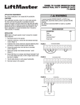
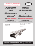
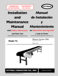
Installation and Maintenance Manual
Barrier Gate Operator
Models BG770 & BG790
Doc 01-G0674
Rev E
2
Contents
Contents
General Product Information _______________________________________________ 4
Specifications _______________________________________________________________________ 4
Safety Instructions ________________________________________________________ 6
Before Installation ____________________________________________________________________ 6
During Installation____________________________________________________________________ 6
After Installation _____________________________________________________________________ 7
Preparing the Installation __________________________________________________ 8
Unpack Carton_______________________________________________________________________ 8
Preparing the Site ____________________________________________________________________ 9
Preparing the Operator _______________________________________________________________ 10
Installation _____________________________________________________________ 11
Step 1:
Mounting __________________________________________________________________ 11
Step 2:
Arm Fabrication _____________________________________________________________ 12
Step 3:
Wiring Connections __________________________________________________________ 13
Step 4:
Arm Attachment _____________________________________________________________ 14
Step 5:
Arm and Turnbuckle Shaft Adjustments __________________________________________ 16
Step 6:
Limit Switch Adjustments _____________________________________________________ 18
Optional Accessories _____________________________________________________ 19
Vehicle Detectors ___________________________________________________________________ 19
Radio Controls______________________________________________________________________ 19
Card Readers, Keypads, or other________________________________________________________ 20
Operating Instructions ____________________________________________________ 21
Electrical Operation__________________________________________________________________ 21
Manual Operation ___________________________________________________________________ 21
Troubleshooting _________________________________________________________ 22
1. Power___________________________________________________________________________ 22
2. Accessories ______________________________________________________________________ 23
3. Primary Voltage Circuit ____________________________________________________________ 23
4. Low Voltage Circuit _______________________________________________________________ 24
General Reference Information_________________________________________________________ 25
Doc 01-G0674
Rev E
Contents
3
Required Maintenance-Normal Usage_____________________________26_Toc509797299
BG770 Drawing and Parts List______________________________________________ 27
BG770 Exploded View _______________________________________________________________ 27
BG770 Parts List ____________________________________________________________________ 28
BG790 Drawing and Parts List______________________________________________ 29
BG790 Exploded View _______________________________________________________________ 29
BG790 Parts List ____________________________________________________________________ 30
01-G1014 Wiring Diagram _________________________________________________ 31
01-G1014 Field Wiring Diagram ____________________________________________ 32
01-G1015 Wiring Diagram _________________________________________________ 33
01-G1015 Field Wiring Diagram ____________________________________________ 34
Warranty Policy__________________________________________________________ 35
Doc 01-G0674
Rev E
4
General Product Information
General Product Information
Specifications
Specifications are for both model BG770 and model BG790 unless otherwise noted.
POWER
Line voltage is designated by third suffix of gate part
number. For amp draw, see motor nameplate.
-11; 115VAC, 1 Phase, 60Hz
-21; 230VAC, 1 Phase, 60Hz
-81; 208VAC, 1 Phase, 60Hz
-83; 208VAC, 3 Phase, 60Hz
-23; 230VAC, 3 Phase. 60Hz
-43; 460VAC, 3 Phase, 60Hz
-53; 575VAC, 3 Phase, 60Hz
MODEL BG770
TYPICAL
INSTALLATION
17”
17”
MOTOR
Squirrel cage induction type (3 phase) or capacitor
start induction type (1 phase), continuous duty, 1725
RPM. Horsepower is designated by second suffix of
operator part number.
DIMENSIONS
-50; 1/2 Horsepower
OVERLOAD PROTECTION
Automatic reset (3 phase operators) or manual reset
(1 phase operators) thermal overload.
44”
35”
Up to 12 ft.
01-G0674F3
Figure 1
MODEL BG790
ELECTRICAL BOX
NEMA 1 general purpose painted steel enclosure,
contains all motor control equipment. Enclosure
removable from operator.
CONTROL CIRCUIT
TYPICAL
INSTALLATION
Class II, 24VAC
LIMIT SWITCHES
Counterweighted
Wishbone Arm
Adjustable, driven limit switches, operate in class II
circuit. Not affected by removal of motor.
17”
22”
17”
POWER ON/OFF SWTICH
Enclosed toggle switch, HP rated.
Up to 24 ft.
DIMENSIONS
44”
35”
01-G0674F4
Figure 2
Doc 01-G0674
Rev E
General Product Information
5
OPERATION
Prewired terminal strip accepts field connection of any access control device with normally open
(N.O.) output contact (most access control equipment) and when required, a separate
OPEN/CLOSE pushbutton (supplied).
Plug-in connectors are included for addition of a loop detector to open and/or a loop detector to
hold open (not supplied). Activation of access device open button, or loop detector to open will
raise gate. Gate will lower automatically unless hold open loop detector is activated or unless
CLOSE button wiring has been made, in which case gate will remain open until CLOSE button is
pushed.
An optional timer will extend the time that the gate remains open. AUTO/MANUAL switch holds
arm in vertical position.
SPEED REDUCTION
Wormgear-in-oil-bath, 60:1
ARM TYPE
MODEL BG770: One piece type to 12 feet.
MODEL BG790: Counterweighted wishbone type to 24 feet.
ARM SPEED
MODEL BG770: Opens in 4 seconds
MODEL BG790: Opens in 11 seconds
LUBRICATION
Permanently lubricated bearings in motor. Low temperature gear oil normally never needs
replacement. Gear oil is Mobil SHC 630 or equivalent.
MOUNTING
Pad mount
ENCLOSURE
Weatherproof, heavy gauge, pregalvanized steel, powdercoat finish, top and side access covers
with key lock.
Doc 01-G0674
Rev E
Safety Instructions
6
Safety Instructions
WARNING
To reduce the risk of injury or death, it is important to read all safety instructions.
These safety instructions have been prepared by LiftMaster, the manufacturer of the barrier gate. As
the manufacturer of only part of the total barrier gate system, we do not know what type of controls or
safety equipment that has been selected as part of your system.
An automatic vehicular gate arm is a large, heavy object that moves with the help of an electric motor.
A moving gate arm can cause serious injury or death. Your safety and the safety of others
depends on you reading, understanding, and following through on the safety instructions in this
manual. It is important that both the installer and end users are aware of the hazards of your specific
system.
If you have any questions or doubts about the safety of your system, or if you do not completely
understand everything in this manual, contact LiftMaster.
Before Installation
! Installation of this barrier gate must be done by a qualified installer.
! Check to make sure that the available power supply to be connected to the operator is of the
same voltage, phase, frequency, and wattage as indicated on the nameplate of the operator.
! Installation and wiring must be in compliance with local building and electrical codes.
! It is strongly recommended that you use safety equipment with this barrier gate
operator. There are many types of safety devices available; sensing edges, photo-electric
controls, motion detectors, and vehicle detectors are some of the more common types.
Audible and/or visible warning devices are recommended when automatic controls are used in
the gate operating system.
If you need advice regarding the type of safety equipment that should be used on your
application or wish to purchase such equipment, contact the supplier of the barrier gate, or
contact LiftMaster. Without safety equipment, the gate could cause serious injury or
death.
! Carefully plan the location of barrier gate control equipment. Do not locate controls in places
where children will be able to reach or play with them. Be sure the person operating the
controls can see the full area of movement of the gate arm from the point of operation.
During Installation
! Do not place hands or fingers in or near the barrier gate unless power is off. Moving chains,
pulleys, or belts can catch clothing or fingers and cause severe injury.
! Always disconnect power and lock out whenever installing or servicing the barrier gate.
! If the barrier gate utilizes any automatic means of operation (such as automatic timed
closings), post warning signs that are clearly visible to persons in the area warning of the
particular hazards of the system.
Doc 01-G0674
Rev E
Safety Instructions
7
After Installation
! Be sure that the operator, controls, and safety devices have been tested and are functioning
properly.
! Review the operation of the gate and safety equipment with the owner or end user. Be sure
that the end user is aware of all safety instructions and hazards of the operating system.
! Inform the owner or end user that the barrier gate and all control and safety equipment should
be maintained regularly. The entire gate system should be checked at least once monthly to
ensure that it is functioning properly.
With a safety edge installed, the gate must reverse on contact with a rigid object. If noncontact sensors are connected to the Hold Open input and an object activates them, the
operator will stop a closing gate. After adjusting the force or the limit of travel, retest the gate
operator. Failure to adjust and retest the gate operator properly can increase the risk of injury
or death.
! Leave all installation manuals, instructions, and safety information, including this manual, with
the owner or end user.
! The entrance is for vehicles only. Pedestrians must use separate entrance.
! Keep gates properly maintained. Read the owner's manual. Have a qualified service
person make repairs to gate hardware.
Doc 01-G0674
Rev E
Preparing the Installation
8
Preparing the Installation
Unpack Carton
1
Unpack the carton, checking for possible damage during shipping. The arm (when supplied) is
packed separately. Damage claims must be filed with the freight carrier.
2
Check that the nameplate data (inside service cover) accurately matches the operator that
was ordered.
3
Verify that the following parts are included with the standard unit.
MODEL BG770 PACKING LIST
PART NUMBER
02-102
07-8007
01-G0674
10-8007M
80-G0187
82-NH38-06
82-HN50-25
82-RH-50
85-LS-50
01-G0674
DESCRIPTION
OPEN/CLOSE PUSH BUTTON
GATE ARM HUB
MANUAL
GATE BRACKET
1/2 x 1/2 x 1-3/8L KEY
3/8-16 x 3/8 CONE POINT SET SCREW
1/2-13 x 2-1/4 HEX BOLT
1/2-13 HEX NUT
1/2 SPLIT LOCK WASHER
BG770 & BG790 MANUALS
QUANTITY
1
1
1
1
1
2
4
4
4
1
Table 1
MODEL BG790 PACKING LIST
PART NUMBER
DESCRIPTION
QUANTITY
02-102
07-8007
10-8055
80-G0135
80-G0187
82-HN50-25
82-HN50-28
82-NH38-06
84-RH-50
84-WH-38
85-FW-38
85-FW-50
85-LS-50
01-G0674
OPEN/CLOSE PUSH BUTTON
ARM HUB
COUNTER WEIGHT CLAMP
3/8-16 x 18 THREADED ROD
1/2 x 1/2 x 1-3/8 KEY
1/2-13 x 2-1/4 HEX HEAD BOLT
1/2-13 x 3 HEX HEAD BOLT
3/8-16 x 3/8 CONE POINT SET SCREW
1/2-13 HEX NUT
3/8-16 SERRATED FLANGE NUT
3/8 FLATWASHER
1/2 FLATWASHER
1/2 SPLIT LOCK WASHER
BG770 & BG790 MANUALS
1
2
2
2
2
12
2
4
14
8
8
8
16
1
Table 2
Doc 01-G0674
Rev E
Preparing the Installation
9
Preparing the Site
1
Be sure that selected gate location has required clearance for arm movement (and
counterweights on model BG790). Refer to the dimensional drawings, Figure 1 and Figure 2
on page 4.
2
Run electrical power to the site according to local electrical codes. See Table 3 below for
correct wire size and length of run (see also Figure 3). If the wire gauge is too high (wire too
small) or the run is too long, the gate may not run properly or may not run at all. Damage to
components may result.
IMPORTANT NOTE: Be sure that the available power is the proper voltage, phase,
frequency, and amperage to supply the gate. Refer to gate nameplate located inside the
service cover.
3
Select locations for control equipment and run any control wiring that may be needed (such as
loop wires, card readers, ticket spitters, pushbuttons, etc.).
WIRE SIZING CHART
SINGLE PHASE
115VAC
AWG
6
8
10
12
700
450
275
175
THREE PHASE
230VAC
230 VAC
460 VAC
Maximum Length of Wire Run in Feet
3,100
4,750
14,225
1,925
3,000
8,975
1,225
1,900
5,650
775
1,175
3,525
575VAC
35,550
22,425
14,075
8,825
Table 3
Note: Install Line Power Here. Do Not
Install Line Power in Panel shown below.
Power switch should be in the OFF position.
AUTO/MANUAL switch should be
in the “AUTO” position.
01-G0674F5
Figure 3
Doc 01-G0674
Rev E
Preparing the Installation
10
Preparing the Operator
CAUTION
Never open electrical cabinet cover unless power is off. Electrical shock and serious injury could
result.
1
Remove the wood base from the unit and discard.
2
Locate the keys for the access panel (taped to the arm mounting flange) and remove.
3
Open the side access panel and check the position of the power ON/OFF switch.
4
Open the cover of the electrical cabinet and be sure that the AUTO/MANUAL switch is in the
"AUTO" position.
5
OPTIONAL CONTROL EQUIPMENT: If loop detectors, radio controls, or other control
equipment will be added at the site, do so now. Refer to the instructions in this manual for
installation of factory supplied optional open and/or hold open loop detectors, and for
connection of factory supplied optional radio controls (see Optional Accessories on page
19).
Doc 01-G0674
Rev E
Installation
11
Installation
Step 1:
Mounting
1
Layout the concrete pad as detailed in Figure 4. Be sure to locate electrical conduit inside the
hatched 14" x 13" area.
2
Excavate required area for pad and conduit. Pad depth should be below the frost line, or as
required by local codes.
3
Locate four 1/2" X 6" long L-bolts (not supplied) as shown in Figure 4. The L-bolts should
protrude 1 1/2" inches above the pad.
4
Pour concrete, insuring that the pad is level and above the ground line.
5
Allow the concrete to set at least two days before installing gate.
Figure 4: Concrete Pad Layout
Doc 01-G0674
Rev E
Installation
12
Arm Fabrication
Step 2:
MODEL BG770 (SINGLE ARM)
If you are making the arm yourself, refer to Figure 5 and its suggestions for the single arm
design.
1
Drill four 1/2" diameter holes using the arm clamp as a template. Tapering the wood as
shown helps reduce the weight and allows you to reduce any warping common with long
lengths of lumber.
2
Finish arm with exterior grade paint and stripe with paint or adhesive backed tape as
required.
3”
Length as Needed
up to 12 feet
Material:
6: x 1” Pine or Redwood
5-12”
01-G0674F7
Figure 5
MODEL BG790 (WISHBONE ARM)
A twenty-four foot wishbone arm is supplied as standard with every BG790 gate. If a shorter arm
is desired the extension may be shortened. See Figure 6. The maximum arm extension is 8 feet
for a total arm length of 24 feet.
1
Cut to desired length.
2
Finish with an exterior grade paint and stripe with paint or adhesive backed tape as
required.
Up to 8 feet
Arm
Extension
Material:
4: x 1” Pine or Redwood
01-G0674F8
Figure 6
Doc 01-G0674
Rev E
Installation
Step 3:
13
Wiring Connections
Locate the electrical enclosure inside the cabinet. The enclosure (shipped loose) may be removed
from the cabinet to help in the connections described below. When all connections are complete, hang
the enclosure as described in step 7.
WARNING
Consult local electrical codes for permanent wiring requirements at you installation site.
1
Open the cover of the electrical enclosure. Refer to the wiring diagram supplied inside for all
electrical connections.
2
Be sure that power supply is of the correct voltage, phase, frequency, and amperage to supply
operator. Refer to the operator nameplate on electrical cabinet cover.
CAUTION
Do not turn on electrical power until you have carefully read the Limit Switch Adjustments
section on page 18. Also, this unit must be properly grounded. A ground screw is supplied in
the switch box for connection of the power supply ground wire. Failure to properly ground
this unit could result in electrical shock and serious injury.
3
Connect power supply wires to the ON/OFF power switch as shown on the operator wiring
diagram and Figure 3 (see page 9). Do Not connect power at control panel (L1, L2, L3).
Route wires away from belt and limit switches.
4
A two button control station (OPEN/CLOSE) is provided as standard equipment with every
BG770 and BG790 barrier gate. If you are not using automatic controls to control the gate, the
two button station may be connected as shown on the wiring diagram supplied with the gate to
control the gate manually. However, the AUTO/MANUAL switch should be kept in the "AUTO"
position.
IMPORTANT NOTE: Use 16 gauge wire or larger for all control wiring connections. If the
control wire is too small, damage to the operator components may result.
5
The control station must be mounted in a location adjacent to and within clear sight of the
gate. If you will mount the control station outdoors, replace the standard station supplied with
the operator with a weatherproof station.
6
The BG770 and BG790 barrier gates will interface with almost all types of commonly used
control stations, radio controls, and access control equipment. Refer to the wiring diagram for
connection of these devices.
If you are using a loop detector to open and/or hold open and close, mounting space and plugin harnesses are provided in the electrical cabinet for installation of optional factory supplied
detectors. You may also use other detectors. Refer to the Optional Accessories section on
page 19.
7
When all wiring connections are complete, mount the electrical enclosure to the shelf housing
shelf. MODEL BG770: Hang electrical enclosure on the two screws provided on the front of
the shelf in the housing. MODEL BG790: Hang electrical enclosure on the two screws
provided on the cross angle under shelf in the housing.
Doc 01-G0674
Rev E
Installation
Step 4:
14
Arm Attachment
For easier access during installation, the top cover of the unit may be opened by removing the two
wing nuts from underneath, inside the cabinet.
WARNING
When following the procedure below, the motor belt will turn and the drive shaft will move
during some of the steps. Keep hands and tools out of the gate cabinet and away from
the belt and drive shaft or serious injury may result. Be sure to disconnect power while
installing the arm attachment.
MODEL BG770: STANDARD ARM
Attach arm to the arm hub flange as shown in Figure 7.
Hub Flange
Gate Arm
Hex Bolt
1/2”-13 x 2-1/4”
Lock Washer & 1/2”-13 Hex Nut
01-G0674F9
Figure 7
MODEL BG770: OPTIONAL ARM
Attach arm to the arm hub flange as shown in Figure 8.
Figure 8
Doc 01-G0674
Rev E
Installation
15
BG790: WISHBONE COUNTERWEIGHTED ARM
Attach left and right arms to the arm hub flanges
as shown and described below.
1
Bolt counterweights to ends of arms clamps
as shown. Use Caution lifting 57lb. weights.
2
Bend and fasten the two arms together as
shown in Figure 10.
If an extension arm is required, sandwich
the extension arm between the two halves
of the wishbone arm before bolting together.
See Arm Fabrication starting on page 12
for extension arm preparation.
3
4
Assemble the two 3/8" threaded rods to the
arms for center support as shown in Figure
10.
Wishbone Arm - Arc of Travel
Ensure adequate clearance for travel of arm.
Turn on power and test the gate.
01-G0674F11
Figure 9
WARNING
Be prepared for gate to start when you turn the power on.
(4) 1/2-13 x 2 1/4”
Bolts
Wishbone
Arm
(4) 1/2” Flatwashers
(4) 1/2” Lockwashers
(4) 1/2” - 13 Hex Nuts
01-G0674F12
Figure 10
Doc 01-G0674
Rev E
Installation
16
Arm and Turnbuckle Shaft Adjustments
Step 5:
CAUTION
Turn off power before making any adjustments.
MODEL BG770 ADJUSTMENTS
1
If necessary, rotate the pulley on the motor by hand until the crank arm on the gear
reducer is perfectly aligned with the turnbuckle shaft (see Figure 11). This is the lowest
point of the arm travel and should be preset in this position at the factory.
2
If the arm is not level, loosen the jam nuts at both ends of the turnbuckle shaft Insert a
screwdriver or other similar tool into the hole in the shaft. Rotate the shaft either CW or
CCW as necessary until the gate arm is in the desired horizontal position. Retighten jam
nuts.
Pivot Arm
Jam Nut
Pulley
Turnbuckle Shaft
Crank Arm
01-G0674F13
Figure 11: Model BG770
BG770 TURNBUCKLE SHAFT ALIGNMENT
If necessary align turnbuckle shaft with center of crank arm for lowest point of travel of pivot arm
(see Figure 12).
01-G0674F14
Figure 12
Doc 01-G0674
Rev E
Installation
17
MODEL BG790 ADJUSTMENTS
1
If necessary, rotate the pulley on the motor by hand until the upper and lower cranks are
in a vertical position (see Figure 13). This is the lowest point of travel and should be
preset in this position at the factory.
2
If the arm is not level, loosen the jam nuts on both the top and bottom end of the
turnbuckle shaft.
3
Rotate the shaft either CW or CCW as necessary until the gate arm is in the desired
horizontal position.
NOTE: While the arm is raising, the upper and lower cranks should travel toward the
side access cover.
Turnbuckle Shaft
Jam Nut
Upper Crank
Arm in closed
position
Lower Crank
Arm in closed
position
See Note
Pulley
01-G0674F15
Figure 13: Model BG790
Doc 01-G0674
Rev E
Installation
18
Limit Switch Adjustments
Step 6:
Open Limit Switch
Close Limit Switch
Auxiliary Close Limit Switch
OPEN
Direction
CLOSE
Direction
01-G0674F16
Figure 14: Limit Switch Layout
CLOSE LIMIT SWITCH
The CLOSE limit switch is preset at the factory. If you rotated the pulley in section Arm and
Turnbuckle Shaft Adjustments (page 16), you will need to reset the cam on the CLOSE limit
switch.
1
Back out the set screw on the cam. Then rotate the cam in the close direction so that the
switch just clicks when the gate arm is in its lowest position (see Figure 14).
2
When the cam is in the desired position, retighten the set screw. This adjustment may
have to be fine tuned after turning on power and running the unit for the first time.
AUXILIARY CLOSE LIMIT SWITCH
The AUXILIARY CLOSE limit switch is preset at the factory. If you made an adjustment to the
CLOSE cam, you will need to adjust the cam on the AUXILIARY CLOSE limit switch also.
1
Position the AUXILIARY CLOSE cam slightly ahead of the CLOSE cam. When the gate
arm is on its down travel, the AUXILIARY CLOSE switch will click just before the CLOSE
switch.
2
When the cam is in the desired position, retighten the set screw.
OPEN LIMIT SWITCH
The OPEN limit switch is preset the factory. This setting may have to be fine tuned after running
the unit for the first time.
1
Loosen the OPEN cam and rotate in the open direction until the switch just clicks. See
Figure 14.
2
Retighten the cam.
Doc 01-G0674
Rev E
Optional Accessories
19
Optional Accessories
CAUTION
Turn off power before working inside gate enclosure.
Vehicle Detectors
Almost all types of vehicle detectors may be used in conjunction with both model BG770 and BG790.
More than one detector may be connected to the gate, and may be mounted inside of the cabinet.
Connect the detector(s) according to the instructions on the wiring diagrams supplied with the gate and
with the detector itself.
FACTORY SUPPLIED PLUG-IN DETECTORS
LiftMaster P/N 71-416-7NH = 24V
Please note: Previous models used 115V detectors (P/N 71-416-3NH).
OPEN LOOP DETECTOR
1
Snap the detector onto one set of the four board mount standoffs located on the inside of
the electrical cabinet. Plug the harness into the connector marked "OPEN".
2
Connect the two loop wires to terminals P1 and P2 as shown on the wiring diagram.
HOLD OPEN LOOP DETECTOR
1
Snap the detector onto one set of the four board mount standoffs located on the inside of
the electrical cabinet. Plug the harness into the connector marked "HOLD OPEN".
2
Connect the loop wires to terminals P3 and P4 as shown on the wiring diagram.
Radio Controls
All types of standard radio controls may be used in conjunction with model BG770 and BG790. If the
receiver is mounted inside of the gate enclosure, a commercial coaxial antenna should be used and
extended through the side of the cabinet.
POWER CONNECTION
All radio receivers require a power supply. If the receiver requires 24 volts AC you may power the
unit from the gate control circuit. To do this, connect the radio receiver power wires to Terminals
#3 and #6 on the control terminal strip. If the receiver requires 115 volts AC or other power, you
will need a separate power source.
A standard residential door radio receiver has a three wire connection marked 1, 2, 3. If you have
this type, you may connect to operator terminals R3, R1, and R6. The transmitter button will open
the gate if it is fully closed.
CONTROL
If you have a standard residential 3 wire receiver and made the power connection described on
page 19, you are finished with the radio connections. If you want to use a radio control (such as a
single button), you must order an optional kit (P/N 90-PGR).
Doc 01-G0674
Rev E
Installation
20
Card Readers, Keypads, or other
Almost all types of access control devices may be connected to models BG770 and BG790. More
than one device may be connected in parallel. All devices connected according to the instructions
below will open the gate and reverse the gate if it is closing.
MOUNTING LOCATION
Mount or install the access control device within sight of the gate and according to the instructions
supplied with the device. Some devices require their own power supply. Do not use the 24 volt
power in the gate to supply other devices. Use either direct line voltage (115V or 230V) or
other external power source as required by the particular device.
NOTE: Most access control devices have an isolated, normally open output contact to
connect to the gate. If yours does not, or if you are unsure of or unfamiliar with these
terms, consult the supplier of the device or a qualified gate installer.
CONTROL CONNECTION
TURN OFF POWER and connect the two output terminals (or wires) of the access control device
to the terminals #1 and #3 on the control wiring terminal strip. Use a wiring method that will
provide permanent, durable, and weatherproof connection between the gate and the access
device.
Doc 01-G0674
Rev E
Operating Instructions
21
Operating Instructions
Electrical Operation
The BG770 and BG790 barrier gate operators are designed to provide years of trouble-free operation.
The gate may be operated by means of the two button control station, or by other means if provided.
ON/OFF POWER SWITCH
The gate is provided with an ON/OFF power switch. To shut power off, remove the access cover
and move the toggle switch on the right side of the main electrical cabinet to the "OFF" position.
OVERLOAD PROTECTION
The motor is protected by either a manual reset (Single Phase unit) or automatic reset (3 phase
unit) thermal overload protector. The overload protector will trip when the motor temperature is
too hot.
DO NOT ATTEMPT TO BYPASS THIS UNIT
If the overload trips, the gate could start by itself when the overload is reset (either manual or
automatic). Exercise caution when resetting the overload. On one phase units, the reset
button is located on the cover of the electrical cabinet.
If after resetting, the overload continues to trip, consult a qualified service company.
Manual Operation
CAUTION
Keep hands clear of moving parts. The motor will start when AUTO/MANUAL Switch is
flipped to the “MANUAL” position.
ACCESS CONTROL “EMERGENCY” BYPASS
To open the gate in an emergency, remove the keyed access cover and open the electrical
cabinet. Flip the AUTO/MANUAL switch to the "MANUAL" position.
The gate arm will remain in the up position, and no other control device will have any effect until
the switch is set back to the "AUTO" position.
Doc 01-G0674
Rev E
Troubleshooting
22
Troubleshooting
When troubleshooting, one of the first things to do is try to isolate the problem area. The four (4) main
areas to check out are:
Power
Accessories
Operator’s Primary Voltage
Operator’s Low Voltage
1. Power
Always use extreme caution! Some possible symptoms of power problems include:
The obvious one is – the operator will not run.
The operator runs slow.
Circuit breakers or fuses keep tripping.
Motor overload keeps tripping.
Operator starts but then stops.
1A.
Using a V.O.M., take a voltage reading at the control transformer’s primary terminals. You should
get a reading as follows:
Nominal Volt.
Min.
Max.
120v.
230v.
460v.
108
207
414
132
253
506
Table 4
If you get a reading that does not fall into the minimum/maximum area, then check out your main
power supply. Also, make sure that the operator was ordered with the proper voltage and phase.
Another item to check is the wire run from the power supply to the operator. Double check the
gauge of the wire versus the distance.
1B.
If the voltage reading is O.K. from 1A, then take the same voltage reading with the operator
running. If voltage drops below the minimum with this reading, then there could be an excessive
current draw somewhere, or a wire AWG is too small.
1C.
In some cases, power drops can occur at only specific times during the day or night. This can be
caused by increased power demands in a general area at a specific time—particularly areas
undergoing rapid growth.
Doc 01-G0674
Rev E
Troubleshooting
23
2. Accessories
Add-on accessories can create many of the problems that are credited to the operator. Many
applications have more than one accessory item attached to the operator and some of these items
even draw their power from the operator.
Some of the symptoms that can show up because of accessories:
The operator won’t close.
The operator will not run.
The operator won’t open.
The operator begins to run, then stops or reverses.
2A.
Whenever the problem is thought to be an accessory and there are more than one connected to
the operator, always disconnect one accessory at a time and then test the system. This will
hopefully isolate which item is causing the problem.
2B.
If an accessory item is being used as an access control device (used to open or close), falls in the
closed position or sends out a continuous signal. The operator will hold the gate in one position
until the signal from the accessory is removed.
2C.
In some applications, the gate may begin to move then either stop or stop and reverse within a
couple of seconds. This can be caused by an external obstruction device that has failed.
2D.
If there are many accessories attached to and powered by the operator, there may be too much
current draw for the operator’s control transformer. This operator can only supply approximately 2
amps @ 24 vac. Double check all accessories for their current requirements.
3. Primary Voltage Circuit
Use extreme caution when troubleshooting the primary voltage circuit! There are five (5) items
in this circuit that could be causing trouble, and they are:
Motor
Contactor (see Figure 15)
Transformer
Power Disconnect Switch
3A.
The first thing to check is the incoming power. Is it there
at the incoming side of the power disconnect switch?
3B.
If there is power, then check for it at the transformer
primary terminals. If there is voltage at the switch and
none at the transformer, then you probably have a bad
power disconnect and it should be replaced. Check
secondary output of transformer for 24VAC output.
01-G0674F17
Figure 15
Doc 01-G0674
Rev E
Troubleshooting
24
3C.
If 3a and 3b check out O.K., then manually disconnect the operator from the gate. Very carefully,
using a screwdriver with an insulated handle, press down on the open side of the contactor. Then
do the same to the close side of the contactor. Did the operator run in both directions? If it did,
the problem may be in the low voltage control circuit. It if did not, then the problem is either in the
contactor or the motor.
3D.
If the contactor is suspected to be causing the problem, first carefully check all wiring connections
at the contacts (see Figure 15). Disconnect Power! Using a V.O.M., take continuity readings
across the contacts of the contactor. Remove wires from one side of the contactor. Place one
probe on 1 and the other on 2. You should get NO continuity; now press down on the contactor;
you should get a continuity reading. Repeat this on all of the contactor’s contact points.
3E.
If the problem is thought to be the motor, it is recommended that it be replaced. It is possible that
the thermal overload inside the motor has overheated. Wait approximately 15 minutes, then try
running unit.
NOTE: Some motors have the overload built into the motor itself, while other units have a
separate overload in the controller (Model BG770 uses a manual reset overload).
4. Low Voltage Circuit
4A.
The first thing to check is the circuit breaker.
4B.
The secondary voltage must be between 22 and 30 vac. This voltage can be checked at the
circuit board at terminals 3 & 6.
4C.
The contactor coils receive 24vac. To activate the motor in either the open or close direction.
There are two contactor coils (one for open and one for close).
4D.
The limit switches are S.P.D.T. (single pole, double throw). These limit switches tell the operator
to shut off at either the full open or full close position.
Doc 01-G0674
Rev E
Troubleshooting
25
General Reference Information
THE GATE
Double check the gate and its related hardware. Does the gate move freely? Are there
unprotected pinch points? - If yes, then correct.
WIRING DIAGRAM
Always reference the wiring diagram that was supplied with the operator. Note that some of the
accessory items may have their own wiring diagram.
If you cannot correct the problem or if you feel you will require technical assistance, contact your
local distributor or dealer. If you do not have a distributor or dealer, then contact us for technical
assistance. Please when calling for assistance, make sure you have the gate operator model
number, voltage, phase, horsepower and a list of all accessories that are attached to the operator.
Doc 01-G0674
Rev E
Required Maintenance – Normal Usage
26
Required Maintenance-Normal Usage
Check at least once
every (#) of months
ACTION
Check for proper operation
Make sure they are present
Check for excessive slack and lubricate
Check for set screw tightness
Inspect for wear or damage
Check all for proper operation
Inspect all wire connections
Check for tightness
Inspect for wear or damage
1
!
!
3
6
!
!
!
!
!
!
12
Complete Checkout
ITEM
External safety systems
Gate caution signs
Drive chain (see notes)
Sprockets & pulleys
Gate
Accessories
Electrical
Frame bolts
Total unit
Table 5
CAUTION
When servicing, always disconnect operator from electrical power supply.
NOTES
Inspection and service should always be
performed anytime a malfunction is
observed or suspected.
Limit switches may have to be reset after
any major drive chain adjustments.
BG790: If lubricating chain, use only a
proper chain lub spray or a lightweight
motor oil. Never use grease or silicone
spray.
When servicing, please do some “house
cleaning” of the operator and the area
around the operator. Pick up any debris in
the area. Clean the operator if needed.
Severe or high cycle usage will require
more frequent maintenance checks.
It is suggested that while you are at the
site, take some voltage readings of the
operator. Using a VOM, double check the
incoming voltage to the operator to make
sure it is within ten percent of the
operator’s rating.
While you are at the site, now would be a
good time to let the owner or manager
know about any new items available or
any safety items that could and should be
added to the site.
LIMITED BEARING LUBRICATION
The barrier gates require very little in the way of maintenance. Motor and shaft bearing normally
should not require lubrication. The gear oil in the gear reducer is sealed in. Unless a severe
problem causes a seal to break, it should never need replacement. If gear oil is required, use
Mobilube C SAE140 or equivalent.
GREASE TURNBUCKLE
Periodically grease the ball ends of the turnbuckle, depending on the gate’s frequency of use.
Doc 01-G0674
Rev E
BG770 Drawing and Parts List
27
BG770 Drawing and Parts List
BG770 Exploded View
Doc 01-G0674
Rev E
BG770 Drawing and Parts List
28
BG770 Parts List
STANDARD PARTS
PART NO.
02-102 (N)
03-8024-K
03-ABDIN-4 (N)
07-8003
07-8004
07-8005
07-8007
10-3522
10-8001-T
10-8007M
10-8014
10-8016-T
10-8017-T
10-8021
10-8022
N/A
11-8031
12-8032
12-8033
12-8034
13-8000 (N)
13-8001 (N)
16-8001
17-2001
17-2002
21-3260-1
23-2017
23-2761
23-8001
24-24-1
24-24-6
28-3000
28-8003
31-10-17
31-2712
32-8002
42-110-2
42-3608 (N)
65-1209
74-G0120 (N)
80-1003
80-1904N (N)
QTY.
1
1
1
1
1
1
1
2
1
1
1
1
1
1
1
N/A
1
2
1
1
14
1
1
1
1
1
3
1
1
1
1
1
1
2
6
1
1
1
1
1
1
8
DESCRIPTION
KEY SWITCH
3 POLE CONTACTOR
DIN RAIL
LOWER CRANK
UPPER CRANK
CRANK LINK
GATE ARM HUB
REDUCER SHIM
TAN BARRIER GATE ENCLOSURE
GATE BRACKET
SWITCH BRACKET
TAN TOP COVER
TAN ACCESS COVER
ELECTRICAL PANEL
ELEC. PANEL MOUNT. BRACKET
N/A
SHAFT
4 BOLT FLANGE
FEMALE ROD END
FEMALE ROD END
METAL GASKET
RUBBER GROMMET
V-BELT
8" PULLEY
2" PULLEY
TRANSFORMER
SPDT LIMIT SWITCH
ROCKER SWITCH
TOGGLE OUTLET
24VAC DPDT RELAY
3 PDT 24V RELAY
SWITCH BOX
DUPLEX OUTLET COVER
1-32 x 1/8 SPACER
NYLON SENSOR SPACER
BARRIER GATE GEAR REDUCER
10 POS. TERMINATION BLOCK
8 POSITION TERMINAL BLOCK
SINGLE ARM (OPTIONAL)
115V CONTROL BOX
6-32 TINNERMAN NUT
PART NO.
80-207-36 (N)
80-5001 (N)
80-575
80-8001
80-G0186 (N)
80-G0187 (N)
81-8000 (N)
81-PX06-06T (N)
82-CB31-26 (N)
82-HN25-08 (N)
82-HN25-18 (N)
82-HN31-16 (N)
82-HN50-25 (N)
82-HN52-18
82-HN75-28
82-NH31-06 (N)
82-NH38-06 (N)
82-PX06-28 (N)
82-PX08-04T (N)
82-PX08-10T (N)
82-QN31-12 (N)
82-QN75-26 (N)
82-RS10-20 (N)
82-HN38-24 (N)
84-JH-75 (N)
84-JH-76
84-JH-76L
84-RH-50 (N)
84-RH-75
84-WH-10 (N)
84-WH-25 (N)
84-WH-31 (N)
84-WH-38 (N)
84-WN-25 (N)
85-FW-31 (N)
85-FW-38 (N)
85-FW-50
85-LS-50
85-LS-75 (N)
91-G0122
91-G0128 (N)
QTY.
1
2
6
1
1
1
8
6
4
2
4
4
4
8
1
1
4
2
6
4
2
1
2
4
1
1
1
4
1
2
12
8
4
2
4
4
6
12
2
4
1
DESCRIPTION
1/4 x 1/4 x 1-1/4 KEY
3/16 x 3/16 X 3/4 KEY
3/4 FLATWASHER
ACCESS PANEL LOCK
1/2 x 1/2 x 1-3/4 KEY
1/2 x 1/2 x 1-3/8 KEY
SHOCK MOUNT
6-32 x 3/8 SELF TAPPING SCREW
5/16-18 x 2-1/2 CARRIAGE BOLT
1/4-20 x 1/2 HEX HEAD BOLT
1/4-20 x 1/-1/4 HEX BOLT
5/16-18 X 1 HEX HEAD BOLT
1/2-13 x 2-1/4 HEX HEAD BOLT
1/2-20 x 1-1/4 HEX HEAD BOLT
3/4-10 x 3 HEX HEAD BOLT
5/16-18 x 3/8 SET SCREW
3/8-16 x 3/8 CONE POINT SET SCREW
6-32 X 3 PAN HEAD SLOTTED SCREW
8-32 x 1/4 SELF TAPPING SCREW
8-32 X 5/8 SELF TAPPING SCREW
5/16-18 x 3/4 SQUARE HEAD BOLT
3/4-10 x 2-1/2 SQUARE HEAD BOLT
10-32 x 1-1/2 SLOTTED SCREW
3/8-16 x 2 HEX HEAD BOLT
3/4-10 JAM NUT
3/4-16 JAM NUT
3/4-16 LEFT HAND JAM NUT
1/2-13 HEX NUT
3/4-10 HEX NUT
10-32 SERRATED WASHER HEAD NUT
1/4-20 SERRATED FLANGE NUT
5/16-18 SERRATED FLANGE LOCK NUT
3/8-16 SERRATED FLANGE LOCK NUT
1/4-20 WING NUT
5/16 FLATWASHER
3/8 FLATWASHER
1/2 FLATWASHER
1/2 SPLIT LOCKWASHER
3/4 SPLIT LOCKWASHER
LIMIT COLLAR
ELECTRICAL ENCLOSURE
FAILSAFE BOARD STAND OFF
PARTS DESIGNATED (N) ARE NOT SHOWN ON DRAWING.
PARTS HAVING ONE OR MORE X IN THE PART NO. VARY FROM MODEL TO MODEL. SEE “VARIABLE PARTS” BELOW.
VARIABLE PARTS
VARIABLE
20-XXXX
24-XXXX
25-XXXX
P/N
20-1050B-2
20-3050B-4E
20-3050M-5
24-115-1
24-230-5
25-2006
25-2010
DESCRIPTION
MOTOR: 1/2 HP - 115/208/230VAC - 1Ø - 60hz
MOTOR: 1/2 HP - 208/230/460VAC - 3Ø - 60hz
MOTOR: 1/2 HP - 575VAC - 3Ø - 60hz
115VAC RELAY
208/230VAC RELAY
6A FUSE
10A FUSE
USED ON
BG770-50-11, BG770-50-21, BG770-50-81
BG770-50-23, BG770-50-43, BG770-50-83
BG770-50-53
ALL 115VAC - 1Ø MODELS
ALL 208/230VAC - 1Ø MODELS
BG770-50-21
BG770-50-11
N/A
N/A
N/A
N/A
N/A
N/A
Table 6
Doc 01-G0674
Rev E
BG790 Drawing and Parts List
29
BG790 Drawing and Parts List
BG790 Exploded View
Figure 16
Doc 01-G0674
Rev E
BG790 Drawing and Parts List
30
BG790 Parts List
STANDARD PARTS
PART NO.
QTY.
DESCRIPTION
PART NO.
QT
Y.
8
1
1
4
1
2
1
3
1
4
8
4
2
4
4
4
12
2
18
6
2
1
8
6
2
6
4
2
2
1
1
18
2
10
14
12
8
2
8
12
24
4
38
2
4
1
1
1
DESCRIPTION
02-102 (N)
1
OPEN/CLOSE KEY SWITCH
80-1904N (N)
FAILSAFE BOARD STAND OFF
03-8024-K
1
3 POLE CONTACTOR
80-207-36
1/4 X 1/4 x 1-1/4 DISCONNECT KEY
03-ABDIN-4 (N)
1
DIN RAIL
80-5001 (N)
3/16 x 3/16 x 1-3/4 KEY
07-8007
2
ARM HUB
80-575 (N)
3/4 FLATWASHER
07-8058
1
CRANK LINK
80-8001
ACCESS PANEL LOCK
07-8063
1
UPPER CRANK
80-G0135 (N)
3/8-16 x 18 THREADED ROD
07-8064
1
LOWER CRANK
80-G0185 (N)
1/2 x 1/2 X 2-1/2 KEY
10-8014
1
SWITCH BRACKET
80-G0187 (N)
1/2 x 1/2 x 1-3/8 KEY
10-8016-T
1
TAN TOP COVER
80-G0188 (N)
1/2 x 1/2 x 2 KEY
10-8017-T
1
TAN ACCESS COVER
80-G0211 (N)
5/16 X 1-1/4 STUD
10-8021
1
ELECTRICAL PANEL
81-8000 (N)
SHOCK MOUNT
10-8026
1
BEARING PLATE
82-CB31-26 (N)
5/16-18 x 2-1/2 CARRIAGE BOLT
10-8027 (N)
1
ELECTRICAL PANEL HANGER KIT
82-HN25-08 (N)
1/4-20 x 1/2 SCREW
10-8051-T
1
TAN HOUSING
82-HN25-18 (N)
1/4-20 x 1-1/4 SCREW
10-8055
2
COUNTERWEIGHT CLAMP
82-HN31-16 (N)
5/16-18 X 1 HEX HEAD BOLT
N/A
N/A
N/A
82-HN50-20 (N)
1/2-13 x 1-1/2 HEX HEAD BOLT
11-8061
1
MAIN SHAFT
82-HN50-25 (N)
1/2-13 X 2-1/4 HEX HEAD BOLT
11-8062 (N)
1
INTERMEDIATE SHAFT
82-HN50-28 (N)
1/2-13 X 3 HEX HEAD BOLT
12-8032
5
4 BOLT FLANGED BEARING
82-HN52-18
1/2-20 X 1-1/4 HEX HEAD BOLT
12-8033
1
FEMALE ROD END
82-HN52-20
1/2-20 X 1-1/2 HEX HEAD BOLT
12-8034
1
FEMALE ROD END
82-HN75-26
3/4-10 X 2-1/2 HEX HEAD BOLT
13-8000 (N)
14
METAL GASKET
82-NH31-06CP (N)
5/16-18 X 3/8 SET SCREW
13-8001 (N)
2
RUBBER GROMMET
82-NH38-06CP
3/8-16 X 3/8 CONE POINT SET SCREW
15-5032
1
50B32 SPROCKET
82-PX06-06T (N)
6-32 x 3/8 SELF TAPPING SCREW
15-9020
1
50B12 SPROCKET
82-PX06-28 (N)
6-32 X 3 SCREW
16-8002
1
COGGED BELT
82-PX08-04T (N)
8-32 x 1/4 SELF TAPPING SCREW
17-2001
1
8" PULLEY
82-PX08-10T (N)
8-32 x 5/8 SELF TAPPING SCREW
17-2002
1
2" PULLEY
82-RS10-20 (N)
10-32 x 1-1/2 SCREW
19-5051 (N)
1
#50 CHAIN
82-SH10-18 (N)
10-32 X 1-1/4 SCREW
19-9024 (N)
1
#50 CHAIN MASTER LINK
84-JH-76
3/4-16 JAM NUT
19-9025 (N)
1
#50 CHAIN HALF LINK
84-JH-76L (N)
3/4-16 LEFT HAND JAM NUT
21-3260-1
1
TRANSFORMER
84-RH-50 (N)
1/2-13 HEX NUT
23-2017
3
SPDT LIMIT SWITCH
84-RH-75
3/4-10 HEX NUT
23-2761
1
ROCKER SWITCH
84-WH-10 (N)
10-32 SERRATED WASHER NUT
23-8001
1
TOGGLE/OUTLET COMBINATION
84-WH-25 (N)
1/4-20 SERRATED FLANGE NUT
24-24-1
1
24VAC DPDT RELAY
84-WH-31 (N)
5/16-18 SERR. FLANGE LOCK NUT
24-24-6
1
3PDT 24V RELAY
84-WH-38 (N)
3/8-16 SERRATED FLANGE NUT
28-3000
1
SWITCH BOX
84-WN-25 (N)
1/4-20 WING NUT
28-8003
1
DUPLEX OUTLET COVER
85-FW-31 (N)
5/16 FLATWASHER
31-10-17 (N)
2
1-32 x 1-1/8 SPACER
85-FW-38 (N)
3/8 FLATWASHER
31-2712 (N)
6
NYLON SENSOR SPACER
85-FW-50
1/2 FLATWASHER
32-8002
1
GEAR REDUCER
85-LS-31 (N)
5/16 SPLIT LOCK WASHER
42-110-2
1
10 POSITION TERMINAL BLOCK
85-LS-50
1/2 SPLIT LOCK WASHER
42-3608
1
8 POSITION TERMINAL BLOCK
85-LS-75 (N)
3/4 SPLIT LOCK WASHER
65-1208
1
WISHBONE ARM
91-G0122
LIMIT COLLAR
65-8056
1
COUNTERWEIGHT KIT
91-G0128 (N)
ELECTRICAL ENCLOSURE
74-G0133 (N)
1
CONTROL BOX
94-G0233 (N)
POWER CABLE
80-1003
1
6-32 TINNERMAN NUT
94-G0234 (N)
MOTOR CABLE
PARTS DESIGNATED (N) ARE NOT SHOWN ON DRAWING.
PARTS HAVING ONE OR MORE X IN THE PART NO. VARY FROM MODEL TO MODEL. SEE “VARIABLE PARTS” BELOW.
VARIABLE PARTS
VARIABLE
20-XXXX
24-XXXX
25-XXXX
P/N
20-1050B-2
20-3050B-4E
20-3050M-5
24-115-1
24-230-5
25-2006
25-2010
DESCRIPTION
MOTOR: BM 115/230V 1/2HP
MOTOR: 1/2 HP - 208/230/460VAC - 3Ø - 60hz
MOTOR: 1/2 HP - 575VAC - 3Ø - 60hz
115VAC RELAY
208/230VAC RELAY
6A FUSE
10A FUSE
USED ON
BG790-50-11, BG790-50-21, BG790-50-81
BG790-50-23, BG790-50-43, BG790-50-83
BG790-50-53
ALL 115VAC - 1Ø MODELS
ALL 208/230VAC - 1Ø MODELS
BG790-50-21
BG790-50-11
Table 7
Doc 01-G0674
Rev E
01-G1014 Wiring Diagram
31
WIRING DIAGRAM
(GN)
,
.
(W)
(BK)
115V
AC C ESSORIES
NOTES:
APPLICATIONS:
1) TRANSFORMER PRIMARY VOLTAGE SAME AS OPERATOR LINE VOLTAGE
24V SECONDARY.
2)
RELAY COIL VOLTAGE SAME AS OPERATOR LINE VOLTAGE.
3)
WE RECOMMEND USING A DEDICATED CIRCUIT BREAKER FOR EACH OPERATOR.
CONTROL WIRING TYPE L2
FIELD WIRING
MODEL TYPES:
HORSEPOWER:
VOLTAGE/PHASE:
DRAWING NUMBER:
DATE:
08/28/00
BG770, BG790
1/2
115/230V, 60Hz, 1 PHASE ONLY
01-G1014
REVISION:
D - 9/9/02
ECN:
02-0490
Doc 01-G0674
Rev E
01-G1014 Field Wiring Diagram
32
FIELD WIRING
IT IS IMPORTANT TO READ ALL SAFETY RULES INCLUDED IN THE INSTALLATION MANUAL BEFORE
BEGINNING INSTALLATION. FAILURE TO COMPLY WITH THE SAFETY INSTRUCTIONS MAY RESULT
IN SERIOUS PERSONAL INJURY OR PROPERTY DAMAGE.
CONTROL WIRING
LINE VOLTAGE SUPPLY
MANUAL
OPEN
ON
SWITCH
OFF
SEE
NOTE #1
SEE NOTE #2
SENSING EDGE
115V
OUTLET
SEE
NOTE #3
OPEN BUTTON
OR OTHER
OPEN CONTROL
CLOSE BUTTON
SEE NOTE #2
ELECTRICAL CABINET
WARNING
(SEE NOTE #5)
115V
ACCESSORIES
(0.2A MAX)
OPEN
LOOP
HOLD OPEN
LOOP
1 PHASE
INCOMING
LINE
(SEE NOTE #5)
LOOP WIRE CONNECTIONS FOR
FACTORY SUPPLIED (PLUG-IN)
DETECTORS ONLY
LOOP DETECTORS BY OTHERS
CONNECTIONS FOR LOOP DETECTORS
NOT SUPPLIED BY THE FACTORY
PRESENCE CONTACT OF
LOOP TO OPEN
RADIO CONTROL
CONNECTIONS FOR STANDARD
3-WIRE 24 VAC RADIO CONTROL
PRESENCE CONTACT OF
LOOP TO HOLD OPEN
LOOP WIRES AND POWER FOR LOOP DETECTORS
SHOULD BE DIRECTLY WIRED TO DETECTOR ITSELF.
REFER TO INSTRUCTIONS ACCOMPANYING DETECTOR.
RADIO CONTROL WILL OPEN GATE
AND REVERSE IF CLOSING. IT WILL
NOT STOP OR CLOSE THE GATE.
NOTES:
1) REMOVE THIS JUMPER TO CAUSE GATE ARM TO CLOSE IMMEDIATELY WHENEVER IT IS OPENED, UNLESS A VEHICLE IS ON THE
HOLD OPEN LOOP. IF THIS JUMPER IS NOT REMOVED, ARM WILL REMAIN OPEN UNTIL A VEHICLE ENTERS AND EXITS THE HOLD
OPEN LOOP.
2) ADD JUMPER FROM TERMINAL #8 TO #9 WHENEVER CLOSE BUTTON IS USED. DO NOT USE WITH HOLD OPEN LOOP.
3) 115V UTILITY OUTLET (4 AMP MAX.) PROVIDED ON 115V MODELS ONLY.
4) SEE REVERSE SIDE FOR INTERNAL OPERATOR WIRING.
5) DO NOT CONNECT INPUT POWER LINES TO L1 & L2 TERMINALS. POWER LINES MUST BE CONNECTED TO THE POWER SWITCH.
DRAWING NO.:
01-G1014
Doc 01-G0674
Rev E