1
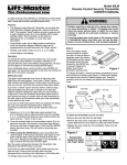
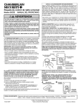
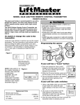
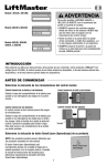
Model 82LM 2-Channel Remote Control
OWNER’S MANUAL
©
To comply with FCC rules, adjustment or modification of receiver and/or
transmitter is prohibited, except for changing the code setting and
replacing the battery. THERE ARE NO OTHER USER SERVICEABLE
PARTS.
Program Receiver to Match Remote Control Code:
Each receiver must be programmed to accept the code of the
remote push buton that will be used to operate the device.
When several remotes will operate the same device, it is only
necessary to use the "smooth" push button of one remote to
program the receiver.
Select a remote control push button to operate the receiver.
• Press and HOLD the selected push button, Figure 1.
• Then press the "SMART" button on receiver panel, Figure 3.
The green indicator light will FLASH once. Release the remote
control push button.
Now the device will operate with the selected remote push button.
NOTE: If the remote push button is not held down until the
indicator light flashes, the receiver has not accepted the
code.
WARNING
WARNING
Children operating or playing with a garage door opener
can injure themselves or others. The garage door could
close and cause serious injury or death. Do not allow
children to operate the wall push button(s) or remote
control(s).
A moving garage door could injure or kill someone
under it. Activate the opener only when you can see the
door clearly, it is free of obstructions, and is properly
adjusted.
ADVERTENCIA
CAUTION
WARNING
Figure 3
The push buttons on the 2-Channel remote controls can
activate garage door openers, entryways and/or light controls.
(Instructions for programming light products are included with
those accessories.)
In general, code switch remote controls are used when
several persons are operating the same device. Code
switches must be set to matching positions in all remote
controls used to operate the same receiver. Follow the
instructions for Figures 1 and 2. Use the "smooth" push
button, as shown in Figure 1, exclusively for code switch
application.
Representative Receiver
with "SMART" Button
1
3
2
9
1
7
3
9
1
7
3
5
5
KG
KG
"Smart"
Green
Button Indicator Light
To Erase All Remote Codes:
Figure 1
Green Test Light
• Press and hold the "Smart" button on the receiver until the
indicator light turns off (about 6 seconds). All the codes the
receiver has learned will be erased.
• Follow code switch setting instructions and reprogram receiver
as described above.
Select Remote
Control Push Button
The Remote Control Battery:
Access the code switches in the 2-Channel remote(s) as
follows:
• Slide back the battery compartment cover on the bottom of the
remote control housing.
0
+
+
0
Figure 2
1 2 3 4 5 6 7 8 9
1 2 3 4 5 6 7 8 9
Match
Code
Switches
(1-9)
Replacement Parts
• Place remote circuit boards side by side. Make sure you set
code switches 1 through 9 in all remotes to matching positions
(see Figure 2). Use a pen or a screwdriver to move the
switches to (+), (-) or (0).
• Replace the battery compartment cover.
114A2025
The green test light should glow and the device should operate
when the remote is activated.
The 12V battery should produce power for at least a year. If the
green test light is dim or does not come on, replace the battery.
To change the battery, slide back the battery compartment
cover. Position the new battery as indicated. Replace the
battery compartment cover.
Visor
Clip
You can attach the remote control to the visor
of your car with the clip provided, if desired.
12V battery ...............................................................................10A14
Visor Clip . . . . . . . . . . . . . . . . . . . . . . . . . . . . . . . . . . . . . . . .29C128
Remote case only (circuit board not included) ....................41A4680
For service, dial our toll-free number: 1-800-528-9131
© 1996, Chamberlain Group, Inc.
All Rights Reserved
Printed in Mexico
Model 84LM Four-Function Remote Control
OWNER’S MANUAL
©
To comply with FCC rules, adjustment or modification of receiver and/or
transmitter is prohibited, except for changing the code setting and
replacing the battery. THERE ARE NO OTHER USER SERVICEABLE
PARTS.
Program Receiver to Match Remote Control Code:
Each receiver must be programmed to accept the code of the
remote push buton that will be used to operate the device.
When several remotes will operate the same device, it is only
necessary to use the "ribbed" push button of one remote to
program the receiver.
Select a remote control push button to operate the receiver.
• Press and HOLD the selected push button, Figure 1.
• Then press the "SMART" button on the receiver panel (see
Figure 3). The green indicator light will FLASH once. Release
the remote control push button.
Now the device will operate with the selected remote push button.
NOTE: If the remote push button is not held down until the
indicator light flashes, the receiver has not accepted the code.
If the "SMART" button is pressed and held until the
adjacent indicator light turns off (about 6 seconds) ALL the
codes the receiver has learned will be erased.
WARNING
WARNING
Children operating or playing with a garage door opener
can injure themselves or others. The garage door could
close and cause serious injury or death. Do not allow
children to operate the wall push button(s) or remote
control(s).
A moving garage door could injure or kill someone under
it. Activate the opener only when you can see the door
clearly, it is free of obstructions, and is properly adjusted.
ADVERTENCIA
CAUTION
The push buttons on the Four-Function remote controls can
activate garage door openers, entryways and/or light controls.
(Instructions for programming light products are included with
those accessories.)
In general, code switch remote controls are used when
several persons are operating the same device. Code
switches must be set to matching positions in all remote
controls used to operate the same receiver. Follow the
instructions for Figures 1 and 2. Use the "ribbed" push
button exclusively for code switch application.
WARNING
Figure 3
1
Representative
Garage Door Opener
Receiver
3
2
9
1
7
9
1
7
3
3
5
5
KG
KG
"Smart"
Green
Button Indicator Light
To Attach the Remote to Your Car Visor:
Figure 1
• Remove the visor clip from the clip holder.
• Remove the case screw. Insert tab on clip holder through
circular label and into case, Figure 4. Slide clip holder forward.
• Replace the case screw (do not overtighten). Slide visor clip
onto clip holder.
Green
Ribbed
Test Light Push Button
Battery
Compartment
Cover
Figure 4
Clip Holder
Visor Clip
Push
Buttons
Connector
Battery
Case
Screw
Tab
Access the code switches in the 84LM, four-function remote(s)
as follows:
• Remove the battery compartment cover as shown in Figure 1.
• Remove the case screw on the housing bottom.
• Hold the remote control as indicated and pull to separate the
housing. Set aside the case top (with push buttons).
Figure 2
Match Code Switches
(1-9)
+
1 2 3 4 5 6 7 8 9
0
Code Switches (1-9)
+
1 2 3 4 5 6 7 8 9
0
Case
Screw
Slide
Clip Holder
Bottom of
Remote
Case
The Remote Control Battery:
The green test light should glow and the device should operate
when the remote is activated.
The 9V battery should produce power for at least a year. If the
green test light is dim or does not come on, replace the battery.
To change the battery, remove the battery compartment cover,
unsnap the connector and remove the old battery (Figure 1).
Insert a replacement battery. Snap the connector onto the new
battery and replace compartment cover.
Code Switches (1-9)
Replacement Parts:
• Place remote circuit boards side by side. Make sure you set
code switches 1 through 9 in all remotes to matching positions
(see Figure 2). Use a pen or a screwdriver to move the
switches to (+), (-) or (0).
• Reassemble case top and bottom by snapping them together.
• Replace the case screw and battery compartment cover.
114A2025
9V battery ..............................10A16 Remote case only.......41A4425
Visor Clip .............................29C128 (circuit board not included)
Visor Clip Holder...............31C412-1
For service, dial our toll-free number: 1-800-528-9131
© 1996, Chamberlain Group, Inc.
All Rights Reserved
Printed in Mexico
Modelo 82LM Transmisor de
control remoto de 2 canales
MANUAL DEL PROPIETARIO
©
WARNING
Para cumplir con las reglas de la FCC, se prohibe el ajuste o modificación del receptor
y/o el transmisor, salvo para cambiar el ajuste del código y reemplazar la batería del
transmisor. NO HAY OTRAS PIEZAS QUE PUEDA REPARAR EL USUARIO.
ADVERTENCIA
Los niños que operen o jueguen con un abre puerta de
garaje pueden lesionarse ellos mismos o a los demás. La
puerta del garaje podría cerrarse y causar lesiones graves
o fatales. No dejar que los niños operen los botones
pulsadores de la pared ni los controles remotos.
Una puerta de garaje en movimiento podría lesionar grave
o fatalmente a alguien bajo la misma. Activar el abre puerta
sólo cuando la puerta esté debidamente ajustada, pueda
verse claramente y no hayan obstrucciones al recorrido de
la puerta.
CAUTION
WARNING
Programar el receptor para que concuerde con el código
del transmisor:
Cada receptor debe programarse para aceptar el código del
botón pulsador del transmisor que se usará para operar el
dispositivo. Cuando hay varios transmisores que vayan a
operar el mismo dispositivo, sólo es necesario usar el botón
pulsador “liso” de un transmisor para programar el receptor.
Como programar los transmisores.
WARNING
• Presionar y SOSTENER el botón pulsador seleccionado, Figura 1.
• Luego presionar el botón inteligente “SMART” en el panel de la
tableta electrónica (ver la Figura 3). La luz indicadora verde
DESTELLARA una vez. Liberar el botón pulsador del transmisor.
Ahora el dispositivo operará con el botón pulsador de transmisor
seleccionado.
NOTA: Si el botón pulsador del transmisor no se sostiene
hasta que destelle la luz indicadora, la tableta electrónica no
ha aceptado el código.
Los botones pulsadores de los transmisores de 2 funciones
pueden activar el abre puertas de garaje, entradas y/o controles
de luces. (Las instrucciones para programar los productos de
luces se incluyen con dichos accesorios.)
En general, los transmisores con interruptores de código
se usan cuando varias personas operan el mismo
dispositivo. Los interruptores de código deben ajustarse
según las posiciones concordantes en todos los
transmisores usados para operar el mismo receptor. Usar
el botón “liso” como lo indica la Figura 1, exclusivamente
para la aplicación de interruptor de código. Seguir las
instrucciones descritas e ilustradas a continuación.
Figura 3
Figura 1
Para borrar todos los códigos del transmisor:
Luz de
prueba verde
Tableta Electrónica
1
3
2
9
1
7
Botón
inteligente
"SMART"
3
9
1
7
3
5
5
KG
KG
Luz indicadora verde
• Presionar y sostener el botón inteligente “SMART” en la tableta
electrónica hasta que se apague la luz indicadora adyacente
(unos 6 segundos).
Todos los códigos que haya almacenado la tableta
electrónica se borrarán. Seguir las instrucciones del ajuste de
los interruptores de código y reprogramar la tableta
electrónica como se describe más arriba.
Seleccionar el botón
pulsador del transmisor
Acceder a los interruptores de código en los transmisores de
2 canales como se indica:
• Deslizar la tapa del compartimiento de batería en la parte
inferior de la caja del transmisor.
0
+
+
0
Figura 2
1 2 3 4 5 6 7 8 9
1 2 3 4 5 6 7 8 9
Interruptores
de código
concordantes
(1-9)
Debe destellar la luz de prueba verde y el dispositivo debe operar
cuando se active el transmisor.
La batería de 12V debe producir energía por lo menos durante un
año. Si se nota atenuada o no se enciende la luz de prueba verde,
reemplace la batería.
Para cambiar la batería, deslizar la tapa
del compartimiento de batería. Posicionar
la nueva batería como se indica. Volver a
colocar la tapa del compartimiento.
Sujetador para
la visera
Se puede instalar el transmisor en la visera del automóvil con el
sujetador provisto, si así se desea.
• Colocar las placas de circuitos unas junto a las otras.
Asegurarse de ajustar los interruptores de código del 1 al 9 en
todos los controles remotos en las posiciones concordantes
(ver la Figura 2). Usar un bolígrafo o un destornillador para
mover los interruptores (+), (-) ó (0).
• Volver a colocar la tapa del compartimiento de la batería.
114A2025
La batería del control remoto:
Piezas de repuesto:
Batería de 12V ...........................................................................................10A14
Sujetador para la visera ...........................................................................29C128
Caja del transmisor solamente (no se incluye la placa de circuitos) ..............41A4680
Para servicio, marcar nuestro número gratis: 1-800-528-9131
© 1996, Chamberlain Group, Inc.
Todos los derechos reservados
Impreso en México
Modelo 84LM Transmisor de control remoto
de cuatro funciones
MANUAL
DEL PROPIETARIO
WARNING
©
WARNING
Para cumplir con las reglas de la FCC, se prohibe el ajuste o modificación del receptor
y/o el transmisor, salvo para cambiar el ajuste del código y reemplazar la batería del
transmisor. NO HAY OTRAS PIEZAS QUE PUEDA REPARAR EL USUARIO.
ADVERTENCIA
Los niños que operen o jueguen con un abre puerta de garaje
pueden lesionarse ellos mismos o a los demás. La puerta del
garaje podría cerrarse y causar lesiones graves o fatales. No
dejar que los niños operen los botones pulsadores de la pared
ni los controles remotos.
Una puerta de garaje en movimiento podría lesionar grave o
fatalmente a alguien bajo la misma. Activar el abre puerta sólo
cuando la puerta esté debidamente ajustada, pueda verse
claramente y no hayan obstrucciones al recorrido de la puerta.
CAUTION
Los botones pulsadores de los transmisores de cuatro funciones
pueden activar abre puertas de garaje, entradas y/o controles de
luces. (Las instrucciones para programar los productos de luces se
incluyen con dichos accesorios.)
En general, los transmisores con interruptores de código se
usan cuando varias personas operan el mismo dispositivo. Los
interruptores de código deben ajustarse según las posiciones
concordantes en todos los controles remotos usados para
operar el mismo receptor. Seguir las instrucciones para las
Figuras 1 y 2. Usar el botón pulsador “estriado”
exclusivamente para la aplicación de interruptor de código.
Programar el receptor para que concuerde con el código
del transmisor:
Cada receptor debe programarse para aceptar el código del botón
pulsador del control remoto que se usará para operar el dispositivo.
Cuando hay varios transmisores que vayan a operar el mismo
dispositivo, sólo es necesario usar el botón pulsador “estriado” de
un control remoto para programar el receptor.
Seleccionar un botón pulsador del transmisor para operar el
receptor.
• Presionar y SOSTENER el botón pulsador seleccionado, Figura 1.
• Luego presionar el botón inteligente “SMART” de la tableta
electrónica (ver la Figura 3). La luz indicadora verde
DESTELLARA una vez. Liberar el botón pulsador de la tableta
electrónica.
Ahora el dispositivo operará con el botón pulsador de control
remoto seleccionado.
NOTA: Si el botón pulsador de la tableta electrónica no se
sostiene hasta que destelle la luz indicadora, el receptor no ha
aceptado el código.
Si se presiona el botón inteligente “SMART” y se sostiene hasta
que se apague la luz indicadora adyacente (unos 6 segundos)
TODOS los códigos que haya almacenado en la tableta
electrónica se borrarán.
WARNING
Figura 3
Tableta Electrónica del
abre puerta de garaje
representativo
1
3
2
9
1
7
Figura 1
Luz de
prueba verde
Tapa del
compartimiento
de batería
Botón
inteligente
"SMART"
Botón pulsador
estriado
9
1
7
3
5
KG
KG
Luz indicadora verde
Para conectar el transmisor a la visera del automóvil:
• Retirar el sujetador de la visera del portasujetador.
• Retirar el tornillo de la caja. Insertar la lengüeta del portasujetador
a través de la etiqueta circular y en la caja (Figura 4). Deslizar el
portasujetador hacia adelante.
• Volver a colocar el tornillo de la caja (no apretar en exceso).
Deslizar el sujetador de la visera en el portasujetador.
Botones
pulsadores
Conector
Batería
Acceder a los interruptores de código en los transmisores de cuatro
funciones 84LM como se indica:
• Retirar la tapa del compartimiento de batería como lo ilustra la
Figura 1.
• Retirar el tornillo de la caja de la parte inferior.
• Sostener el transmisor como se indica y tirar para separar la caja.
Dejar a un lado la parte superior de la caja (con los botones
pulsadores).
Figura 2
3
5
Interruptores de código concordantes
(1-9)
Figura 4
Portasujetador
Sujetador
para la visera
Tornillo de
la caja
Lengüeta
Tornillo de
la Caja
Deslizar el
portasujetador
Parte inferior
de la caja del
transmisor
La batería del transmisor:
+
1 2 3 4 5 6 7 8 9
0
Interruptores de código (1-9)
+
1 2 3 4 5 6 7 8 9
0
Interruptores de código (1-9)
• Colocar las placas de circuitos unas junto a las otras. Asegurarse
de ajustar los interruptores de código del 1 al 9 en todos los
transmisores en las posiciones concordantes (ver la Figura 2).
Usar un bolígrafo o un destornillador para mover los interruptores
(+), (-) ó (0).
• Volver a ensamblar la parte superior e inferior de la caja
presionándolas para unirlas.
• Volver a colocar el tornillo de la caja y la tapa del compartimiento
de la batería.
114A2025
Debe destellar la luz de prueba verde y el dispositivo debe operar
cuando se active el transmisor.
La batería de 9V debe producir energía por lo menos durante un
año. Si se nota atenuada o no se enciende la luz de prueba verde,
reemplace la batería.
Para cambiar la batería, retirar la tapa del compartimiento de
batería, desprender el conector y retirar la batería vieja (Figura 1).
Insertar una batería de repuesto. Presionar para instalar el conector
en la nueva batería y volver a colocar la tapa del compartimiento.
Piezas de repuesto:
Batería de 9V .............................................................................................10A16
Sujetador para la visera ...........................................................................29C128
Portasujetador para la visera ................................................................31C412-1
Caja del transmisor solamente (no se incluye la placa de circuitos) ..............41A4425
Para servicio, marcar nuestro número gratis: 1-800-528-9131
© 1996, Chamberlain Group, Inc.
Todos los derechos reservados
Impreso en México