1
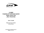
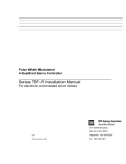
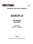
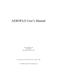
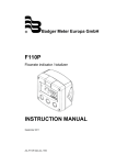
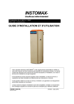
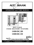
INSTALLATION & MAINTENANCE
INSTRUCTIONS
A E R O F AN S U P E R I O R B A T H R O O M F A N S
READ AND SAVE THESE INSTRUCTIONS FOR FUTURE REFERENCE
PACKAGE CONTENTS
•
•
•
AeroFan superior bathroom fan
Mounting brackets (3)
Lamps - 26W PL & 4W night light (selected models only)
BEFORE INSTALLATION
WARNING!
TO REDUCE THE RISK OF FIRE, ELECTRICAL SHOCK, OR
INJURY TO PERSONS, OBSERVE THE FOLLOWING:
1.
2.
3.
4.
5.
6.
7.
8.
9.
10.
11.
12.
13.
14.
15.
16.
17.
18.
Use this unit in the manner intended by the manufacturer.
If you have any questions, contact the manufacturer.
Before servicing or cleaning unit, switch power off at service
panel and lock the service disconnecting means to prevent
power from being switched on accidentally. When the service
disconnecting means cannot be locked, securely fasten a
prominent warning device, such as a tag, to the service panel.
Installation work including the electrical wiring must
be done, in accordance with all applicable codes and
standards, by a qualified person.
When cutting into ceilings, take care not to damage
concealed electrical wiring or any other hidden utilities.
Ducted fans must always be vented to the outdoors.
NEVER place a switch where
Cooking area
it can be reached from a
Do not install above
tub or shower. To prevent
or inside this area
electrical hazards the fan
must be installed so as to
45o
45o
prevent water from entering
the fan. The fan must not be
installed in a place that is
Cooking
prone to water leakage.
Equipment Floor
Not for use in cooking
areas. (Figure 1)
Figure 1
These fans must be mounted
to structural members that are strong enough to support
the fan’s weight.
The fan must be properly grounded.
Do not allow foreign objects to enter the fan; this could
result in electric shock or fan damage.
Do not block the air intake or exhaust.
The fan should not be turned on and off rapidly.
If the fan is not operating properly, shut the power off
immediately, and have a certified electrician inspect it and
have it serviced as required.
Do not clean the fan with corrosive chemicals nor water in
excess of 60C (140F).
Power supply wiring is to be No. 14AWG wire or larger
(suitable for at least 90C (190F)).
Not for use outdoors.
For the lighted units, use only PL type 26W lamps and
a maximum of 4W type E12 T20 lamp for the night light
(models TBFR90L, TBFS90L, TBFR120L, TBFS120L).
The fan is type IC (Inherently Protected).
19. The fan must not be installed in a ceiling with an “R” rating
greater than 40.
20. To reduce the risk of injury, install the fan at least 2.1m
(7 feet) above the floor.
21. The following models are suitable for installation over a
shower or tub when installed in a GFCI protected branch
circuit (TBF90, TBF120, TBFR90L and TBFR120L).
22. WARNING: To reduce the risk of fire or electrical shock, do
not use this fan with any solid state speed control device.
CAUTION!
1.
2.
3.
4.
For general ventilating use only. Do not use to exhaust
hazardous or explosive materials and vapors.
This product is designed for installation in flat ceilings
only. Do not install it in a sloping ceiling or in a wall.
To avoid motor bearing damage and noisy unbalanced
impellers keep construction material / dust from entering
the fan.
Please read specification label on the product for further
information and requirements.
FAN INSTALLATION
The fan should only be installed in a ceiling (see figure 2 for a
typical installation). The fan will accommodate a joist spacing
of 16” with a minimum clearance height of 9”.
Power
Housing
Fan Outlet
Ceiling Joist
Grille
Ceiling
Electrical
Box
Electrical
Box Cover
Figure 2
1.
2.
Remove the grille by
gently squeezing the
wire
springs
and
extracting them from
the slots in the housing.
Remove the electrical
box cover and install
the 3 brackets on the
fan housing. (Figure 3) Figure 3
Mounting
Bracket
To install the housing in
the ceiling, position it
between the joists and
extend the brackets to the
adjacent joists. Mark the
screw locations (at the top
of the keyhole on each
bracket) on the joists.
Ceiling
Note: make sure to allow
the appropriate depth for
Figure 4
the particular ceiling type.
The bottom edge of the
housing should be flush with the ceiling. (Figure 4)
4. Remove the housing and drive the screws part way into the
joists at the marked locations.
5. Mount the housing using the screws in the joists and then
secure them tightly. Make all the electrical connections in
the electrical box, per the wiring diagram, and attach the
electrical box cover. Attach the discharge duct tightly onto
the fan outlet.
Note: In order for the fan to operate efficiently, keep the
discharge duct as straight as possible.
6. To complete the installation, install the lamps (if applicable)
and mount the grille.
RECOMMENDED MAINTENANCE
3.
1.
2.
Turn the power off and lock it out prior to servicing or cleaning.
To clean the grille, first remove it from the fan then use a
soft brush and clean water to remove the dirt. If the dirt is
not easily removed, wash with a neutral detergent.
3. In order to remove the impeller and housing for maintenance,
first remove the light, night light and reflector (if applicable).
Then unplug the electrical connection and remove the 4
screws that secure the fan assembly to the housing. To
clean the impeller and housing, remove the motor and then
wash with water or a neutral detergent, as required.
Note: Keep all electrical components away from water. Do not
use corrosive chemicals or water in excess of 60C (140F) to
clean plastic parts.
WIRING PROCEDURE
Refer to the wiring diagram.
FAN SPECIFICATIONS
MODEL
POWER CONSUMPTION (W)
VOLTAGE
(V)
FREQUENCY
(HZ)
MOTOR
PL LAMP
NIGHT LIGHT
SPEED
(RPM)
AIRFLOW
(CFM)
TBF90
120
60
25
--
--
750/1050
60/90
TBF120
120
60
40
--
--
775/1050
90/120
TBFS90L
120
60
25
26
4
750/1050
60/90
TBFS120L
120
60
40
26
4
775/1050
90/120
TBFR90L
120
60
25
26
4
750/1050
60/90
TBFR120L
120
60
40
26
4
775/1050
90/120
CONDENSED WARRANTY
All warranty claims must be processed through point of purchase. All warranty repair work must be authorized by Vendor.
AeroFan Superior Bathroom Fans are warranted against defects in material and workmanship for a period of three years from
date of purchase. Warranty does not include consumable components such as lamps. All other products are warranted for a
period of one year from date of purchase.
WARRANTY DOES NOT APPLY TO:
•
•
•
•
•
•
•
Shipping damage, either concealed or visible. Claims must be filed with the carrier.
Damage caused by improper installation, wiring, or incorrect electrical voltage.
Materials that have been modified, altered, or disassembled.
Damage caused by corrosion, erosion, abrasion or severe temperature.
Materials that have had the identification labels removed or altered.
Materials that have been subjected to abuse, misuse, abnormal usage, or accident.
Materials that have not been properly maintained.
No other warranties, expressed, implied or written shall apply to this product. Vendor will not be responsible for any
consequential or incidental damages, loss of property, revenues or profit, cost of removal, installation, or reinstallation, personal
damage or loss of life, or for any breach of warranty, regardless of how caused.
USA
www.continentalfan.com
Continental Fan Manufacturing Inc.
203 Eggert Rd.
Buffalo, NY 14215
Tel: 716-842-0670 Toll: 800-779-4021 Fax: 716-842-0611
Canada
www.aeroflo.com
Aeroflo Inc.
12-205 Matheson Blvd. East
Mississauga, ON L4Z 3E3
Tel: 905-890-6192 Toll: 800-779-4021 Fax: 905-890-6193
AEROFAN I&M-1005
For a complete description of our Limited Warranty conditions, visit www.continentalfan.com.
AEROFAN WIRING DIAGRAMS
FAN ONLY
(MODELS TBF90, TBF120)
EXHAUST FAN
MODEL TBF90 & TBF120
SWITCH BY OTHERS
OFF
HOT
115V POWER
SUPPLY
HIGH
GREY
LOW
RED
GROUND
FAN
MOTOR
WHITE
NEUTRAL
NOTE:
CAPACITOR
GREEN /
YELLOW
MULTIPLE SINGLE POLE SWITCHES MUST NOT BE USED.
FAN MOTOR FAILURE WILL OCCUR. REQUIRES THE USE OF ONE
THREE POSITION SWITCH FOR OFF, HIGH AND LOW SPEED.
FAN/LIGHT COMBINATION
(MODELS TBFR90L, TBFS90L, TBFR120L, TBFS120L)
TO NIGHT LIGHT BY OTHERS
TO BATHROOM LIGHT BY OTHERS
SPEED CONTROL SWITCH
LEVITON 3 WAY SWITCH
OR EQUAL
EXHAUST FAN
MODEL TBF90 & TBF120
FAN
MOTOR
NIGHT LIGHT
GREY
HIGH
RED
LOW
WHITE
GREEN /
YELLOW
COMMON
LIGHT
FAN
COMMON
BLACK
WHITE
GROUND
117 V
POWER
SUPPLY
AEROFAN I&M-1005
CAPACITOR
3 CIRCUIT CONTROL SWITCH
LEVITON COMBINATION SWITCH
OR EQUAL