1
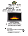
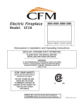
Power Venting System
Model: PVS-1
for use with
Decorative Gas Appliance Models:
NVC33VN/VP, NVC36VN/VP,
NVC39VN/VP, NVC43VN/VP
INSTALLER/CONSUMER
SAFETY INFORMATION
PLEASE READ THIS MANUAL
BEFORE INSTALLING AND USING
APPLIANCE
WARNING: If the information in this
manual is not followed exactly, a fire
or explosion may result causing property damage, personal injury or loss of
life.
FOR YOUR SAFETY
Installation and service must be performed by a qualified installer, service
agency, or the gas supplier.
Do not store or use gasoline or other
flammable vapors and liquids in the
vicinity of this or any other appliance.
FOR YOUR SAFETY
If you smell gas:
• Do not try to light any appliance.
• Do not touch any electric switch; do
not use any phone in your building.
• Immediately call your gas supplier
from your neighbors phone. Follow
the gas supplier’s instructions.
• If you cannot reach your gas supplier,
call the fire department.
• Open windows / Extinguish all flames.
Homeowner’s Installation &
Operating Manual
DE S I GN
CE
CERTIFIED
RTIFI E D
PLEASE KEEP THIS MANUAL FOR FUTURE REFERENCE
51810 1/06 Rev. 2
Majestic® Fireplaces Power Venting System
Installation Instructions
General information and instructions for the power vent
system model No. PVS-1. NOTE: The PVS-1 will only
work in conjunction with a VN Gas Valve P/N 57588
or VP Gas Valve P/N 57587.
1. This power vent system must be installed by a qualified installer in accordance with all applicable local
codes and with the current installation codes for gas
burning appliances CSA-B149.1 in Canada or ANSI
Z223.1/NFPA 54 in the U.S.A.
Electrical connections and grounding must be in accordance with the Canadian Electrical Code, C22.1
Part 1 and in U.S.A., National Electrical Code ANSI/
NFPA70 and/or local codes where applicable.
2. This device must be installed by a qualified professional installer in accordance with these instructions.
If improperly installed, a hazardous condition such
as an explosion or carbon monoxide poison could
result.
3. The Power Vent System #PVS-1 has been certified
by CSA to be installed as a component part and is
for use only with fireplace models listed in the front
page of this manual. Certification is cancelled if
used with other than listed products.
4. Plan the vent system so that code required distances are maintained from plumbing and wiring.
5. The Power Venter motor shaft must be mounted
horizontally to ensure proper operation of the fan
pressure proving switch and to prevent motor bearing wear.
6. Flue gas temperatures must not exceed 470ºF at
Power Venter inlet. Ambient temperature must not
exceed 104ºF.
7. Disconnect power supply when making wiring connections or when working around the fan blade and
motor. Failure to do so may result in severe personal
injury and equipment damage.
8. Make certain the power source is adequate for the
fan motor requirements. Do not add the Power Venter to a circuit where the total load is unknown.
9. This Power Venter System #PVS-1 shall be installed
with Sound Reducer Kit Nos. SR 4 for fireplaces with
a 4” (102 mm) flue collars and SR 5 for fireplaces
with 5” (127 mm) flue collars. See INSTALLATION
RESTRICTIONS Page 5.
Power Vent System Parts and Description
1. Fan Assembly - comes complete with 6’ (1.8 m)
power cord for plugging into a standard house
receptacle. The system is completely pre-wired and
includes the pressure switch and 24 volt transformer.
2
2. 24 Volt Wiring Harness - a 40’ (12m) wiring harness
with plug-in connectors. Eliminates costly time consuming electrical installations.
3. Vent Terminal - the device which exhausts flue
gases into the atmosphere.
4. Fan Mounting Bracket - to secure the fan in a vibration-free mode so as to reduce vibration through the
pipes.
5. Flex-Connector - an additional device to reduce
vibration and noise through the pipes. It is mounted
to the negative inlet side of the fan.
6. Approved 4” (102 mm) diameter insulated aluminum
flex liner, 4” (102 mm) diameter B-Vent* or 4” (102
mm) diameter single wall metal vent connector.
7. Assorted clamps, connectors and wall mounting
brackets.
General Venting Information
Always consult your local codes and authorities, in
the absence of such codes, follow the current installation codes for gas burning appliances CSA-B149.1 in
Canada or ANSI Z223.1/NFPA 54 in the US.
1. Clearance to Combustible Materials:
• 1” (25 mm) for insulated single wall vent or
flexible vent pipe.
• 6” (152 mm) for single wall fan housing.
• 1” (25 mm) for fan motor.
• 1” (25 mm) for B-Vent.*
• 6” (152 mm) for single wall vent or flexible vent
pipe.
* B-Vent can only be used on the negative side of
the power venter - between the appliance and
the power venter - and insulated flexible liner or
single wall vent on the outlet side of the power
venter. To reduce fan noise or condensation,
CFM Corporation recommends all venting pipes
be insulated with a minimum of 1” (25 mm) fiberglass insulation.
2. Total allowable system length is 100’ (30 m) of
straight pipe. Minimum allowable system length is 5’
(1.5 m).
NOTE: Deduct 10’ (3 m) for each 90° elbow and 5’
(1.5 m) for each 45° elbow.
Example: An installation requires 30’ (9 m) of
straight pipe with 45° and three (3) 90° elbow.
Straight pipe
30’ (9 m)
45º Elbow (1) 5’ (1.5 m)
90º Elbow (3) 30’ (9 m)
TOTAL
65’ (19.5 m)
Total equivalent pipe length = 65’ (19.5 m)
51810
Majestic® Fireplaces Power Venting System
3. Vent System Termination
Before installing Power Venter, determine location of
vent system termination.
4. Location of the Fan
To keep the noise level to a minimum, the fan should
be located as far from the appliance as possible.
A storage cupboard, or laundry area are preferred
locations. Permanent access for inspection and
servicing must be provided.
5. All portions of the vent system under positive pressure during operation (on the outlet side of the
Power Venter) shall be designed and installed so as
to prevent leakage of flue or vent gases into a building.
General Code Requirements
Power Venter Specifications
Electrical
Motor voltage .................................... 115
Control Circuit Voltage ........................24
Hz ........................................................60
RPM ................................................3000
Watts ...................................................95
Amps ................................................1.26
Thermal Protection ............................ Yes
Mechanical
Shaded Pole Motor ........................... Yes
Int. Fan Cooled ................................. yes
Shaft Diameter (inch) ........................313
Bearings .............................. Sleeve Type
The exit terminal shall be so arranged that flue gases
are not directed so as to jeopardize the safety of
people, overheat combustible structures or enter
buildings, and that proper clearances are maintained.
Always consult your local codes and authorities. In
the absence of such codes follow the current installation codes for gas burning appliances CSA-B149.1 in
Canada or ANSI Z223.1/NFPA 54 in the US.
Also see Diagram A - Vent Termination Locations.
51810
3
Majestic® Fireplaces Power Venting System
General Venting Information - Termination Location
INSIDE
CORNER DETAIL
V
D
H
A
V
E
L
V
B
V
F
C
B
�����
������
���
���
V
V VENT TERMINATION
B
V
��������
��
B
CFM145a
G
B
V
V
�����
������
J
G
X
B
I
A
X AIR SUPPLY INLET
M
C = Clearance to permanently closed window
D = Vertical clearance to ventilated soffit located
above the terminal within a horizontal
distance of 2’ (610mm) from the center
line of the terminal
E = Clearance to unventilated soffit
F = Clearance to outside corner
G = Clearance to inside corner (see next page)
H = Clearance to each inside of center line
extended above meter/regulator assembly
I = Clearance to service regulator vent outlet
J = Clearance to nonmechanical air supply inlet
to building or the combustion air inlet to any
other appliances
K
X
A
V
V
AREA WHERE TERMINAL IS NOT PERMITTED
Canadian Installations1
A = Clearance above grade, veranda, porch,
deck, or balcony
B = Clearance to window or door that may be
opened
V
G
US Installations2
12” (30cm)
CFM145a
12” (30cm)
6”
< 10,000Btuh (3kW), 12” (30cm)
for appliances > 10,000 Btuh (3kW) and
< 100,000 Btuh (30kW), 36” (91cm)
for appliances > 100,000 Btuh (30kW)
12” (305mm) recommended to
prevent window condensation
6” (15cm) for appliances
< 10,000 Btuh (3kW), 9”
(23cm) for appliances > 10,000
Btuh (3kW) and < 50,000 Btuh
(15kW), 12” (30cm) for
appliances > 50,000 Btuh (15kW)
12” (305mm) recommended to
prevent window condensation
18” (458mm)
18” (458mm)
12” (305mm)
see next page
see next page
3’ (91cm) within a height of 15’ (4.6 m)
above the meter/regulator assembly
3’ (91cm)
6” (15cm) for appliances < 10,000
Btuh (3kW), 12” (30cm) for
appliances > 10,000 Btuh (3kW) and <
100,000 Btuh (30kW), 36” (91cm)
for appliances > 100,000 Btuh (30kW)
DV Termin Location
5/01/01 Rev. 12/05/01
(15cm)
sta for appliances
K = Clearance to a mechanical air supply inlet
6’ (1.83m)
L = Clearance above paved sidewalk or paved
driveway located on public property
M = Clearance under veranda, porch, deck or
balcony
7’ (2.13m)†
12” (305mm)
see next page
see next page
3’ (91cm) within a height of 15’ (4.6m)
above the meter/regulator assy
3’ (91cm)
6” (15cm) for appliances
< 10,000 Btuh (3kW), 9”
(23cm) for appliances > 10,000
Btuh (3kW) and < 50,000 Btuh
(15kW), 12” (30cm) for
appliances > 50,000 Btuh (15kW)
3’ (91cm) above if within 10’
(3m) horizontally
7’ (2.13m)†
12” (30cm)‡
12” (30cm)‡
1 In accordance with the current CSA-B149 Installation Codes
2 In accordance with the current ANSI Z223.1/NFPA 54 National Fuel Gas Codes
† A vent shall not terminate directly above a sidewalk or paved driveway which is located between two (2) single family dwellings and
serves both dwellings
‡ only permitted if veranda, porch, deck or balcony is fully open on a minimum two (2) sides beneath the floor:
NOTE: 1. Local codes or regulations may require different clearances.
2. The special venting system used on Direct Vent appliances are certified as part of the appliance, with clearances tested and ap
proved by the listing agency.
4
51810
Majestic® Fireplaces Power Venting System
Horizontal Discharge
Installation
Vertical Discharge
1. Slip Sound Reducer into flue collar and press on to
fireplace top.
2. Fasten Sound Reducer to fireplace top with four (4)
sheet metal screws supplied.
3. Continue with the power venter installation as per
instructions supplied with same.
4” (102 mm) Insulated Flue Liner
Oil Holes
Motor Shaft
Vertical
Sound Reducer
Sheet Metal
Screws
Fireplace Top
Incorrect
FP1419
Fig. 3 The Power Venter must be mounted with motor shaft
horizontal.
3. Power Venter housing in single wall a 6” (152 mm)
clearance must be maintained. (Fig. 4)
FP1419
motor views
11/25/03 djt
FP1417
Combustible Material
6" (152mm)
Minimum
Fig. 1 Secure sound reducer to fireplace top with four (4)
sheet metal screws.
Sound Reducer Kit SR6
FP1417
1. Although the Power Venter can be installed anypowervent
where in the exhaust system, it is best if it is installed
system of the vent system as
as close to the termination
view
possible to obtainfront
optimal
appliance efficiency and to
11/24/03
djt 2)
prevent flue gas leakage. (Fig.
Combustible Material
Installation Restrictions
Power Venter
6" (152mm)
Minimum
NOTE: 6” (152mm)
maximum clearance from
combustible must be
maintained.
Vent Support Hangers
Spaced 36” (914mm) on
Horizontal Run
6" (152mm)
Minimum
Fireplace
Combustible Material
FP1420
Fig. 4 Minimum clearance.
Anti-Vibration Sleeve
FP1418
Fig. 2 It is best to install Power Venter as close to the termination as possible.
2. Power Venter must be mounted with motor shaft horizontal to ensure proper operation of the fan proving
FP1418
switch and to prevent motor
bearing wear. (Fig. 3)
power vent location
11/24/03 djt
51810
4. Allow for a minimum of 18” (457mm) vertical rise off
the top of the appliance
before the vent makes a 90°
FP1420
Minimum
elbow to the horizontal.
(Fig.clearance
5)
11/25/03 djt
5. Vent pipe transitions, where necessary, should be
gradually tapered. (Fig. 6)
6. Power Venter to vent pipe connections and all joints
on the outlet side of the Power Venter must be
sealed with high temperature silicone sealant or aluminum vent pipe tape to prevent flue gas leakage.
(Fig. 7)
7. The vent terminal must not be more than 20’ (6m)
below the appliance’s flue outlet.
5
Majestic® Fireplaces Power Venting System
18” (457mm)
Minimum
FP1421
Fig. 5 An 18” (457mm) minimum vertical rise is necessary
before a 90° elbow.
FP1421
Min. vertical rise
11/25/03 djt
Incorrect
Correct
FP1423
4. Install optional sound reducer (Model SR5 or SR4)
onto fireplace. See Installation Instructions packaged with sound reducer.
5. Mount Power Venter
NOTE: It is best to locate the fan near the vent
terminal. However, if such a location is not suitable,
the fan can be installed anywhere within the vent
system.
a. Remove vibration isolation mount and retain
the nut from the parts bag and install. Install on
Power Venter as shown in diagram. Next install
flexible duct piece and outlet collar using four (4)
screws to fasten.
b. To prevent vibration, securely support Power
Venter from ceiling or joist with Power Venter
bracket. (Fig. 8)
c. By using 1” (25 mm) bracket, clearance to fan is
maintained at 1” (25 mm). The addition of the 6”
(152 mm) bracket, maintains a 6” (152 mm) clearance to combustibles.
Vertical Mounting
Fig. 6 Vent pipe transitions should be gradually tapered.
Ceiling
Power Venter
Negative Pressure
FP1423
Positive Pressure
pipe transitions
11/25/03 djt
All seams on the
positive side of
power venter to
be sealed with
high temperature
silicone sealant.
Power Venter
Bracket
6” (152 mm)
Bracket
1” (25 mm)
Bracket
Vibration
Isolation
Mounts
Discharge
Fan
Power Venter
FP1424
Horizontal Mounting
Discharge
FP1422
Fig. 7 Vent pipe connections and all joints on the outlet side
of the power venter must be sealed with high temperature
sealant.
FP1422
pipe transitions
Installation
11/25/03
djt
1. Cut 6¹⁄₄” (159mm) diameter hole through outside wall
- see General Code Requirements for proper location.
2. Install vent terminal. Fasten from outside with four
(4) screws and caulk around flange edge.
3. Locate fireplace and fasten to floor as shown in fireplace manual.
6
Wall or
Wall
Studs
FP1424
vertical mounting
11/25/03 djt
Fan
Power Venter Bracket
FP1425
Fig. 8 Power venter mounting options.
FP1425
horizontal mounting
11/25/03 djt
51810
Majestic® Fireplaces Power Venting System
6. Measure distance between fireplace’s flue outlet (top
of Sound Reducer) and fan inlet. Cut flexible duct
and insulate with insulation sleeve sections using
noise cone for ease of mounting. Please note that
wherever possible use continuous length pipe without joints.
7. Apply silicone at both ends, and attach flex pipe to
collars. Secure with clamps (provided). For additional reinforcement, it is recommended that three (3)
sheet metal screws be used at each joint to prevent
pipe from accidentally separating.
8. If fan is located at vent terminal, connect it by first
sealing the joints with silicone. Again use three (3)
sheet metal screws for each joint.
9. Seal all joints with aluminum vent pipe tape and
cover with insulation. Joints between fan and vent
terminal must be absolutely air and water tight to
prevent flue gas or condensation leakage.
10. Support venting duct with plumber’s strap (supplied
by installer). On horizontal runs support vent pipe
every 36” (914mm) to prevent it from sagging.
11. Enclose venting system, if necessary leaving at
least 1” (25 mm) clearance between insulation and
combustible materials and 6” (152 mm) between fan
housing and combustibles.
Electrical Wiring
Electrical connections and grounding must be in accordance with the Canadian Electrical Code, C22.1 Part
1 and in U.S.A., National Electrical Code ANSI/NFPA70
and/or local codes where applicable.
Operation Sequence of 24 VAC
Controlled Appliance
When Power Vent Switch is activated, its closure
completes the 24 VAC electrical circuit from the appliance transformer through the switch to the Power
Venter relay. The 24 volts applied to the relay coil bring
in the 115 volt power to the motor. The air movement
generated by the Power Venter closes the Fan Proving
Switch contacts which allows the switch signal to reach
the 24 volt burner control. The Fan Proving Switch
actually becomes the burner controller and will allow
the appliance to operate only when the Power Venter is
operating.
WARNING: All 120 volt wiring must comply with applicable codes and ordinances.
The optional power venter Model PVS-1 is
equipped with a plug-in cord and an electric knockout. When unit is wired directly
the cord must be removed.
Install 24 Volt wiring harness. Simply plug in connector
at fan electrical box, slide connectors onto gas valve
operator and connect to power switch or if applicable to
thermostat. Refer to Figure 9. Be sure to keep wires
away from heated areas, within the fireplace route wires
along gas line.
Black
L1
White
L2
To Fan*
115 / 1 / 60
Black
N/O Relay
Power
Venter
Motor
Black
White
G
115V
24V
Thermostat
Blue
Blue
*If optional fan and/or power
venter is used, wire electrical
system as shown in diagram.
(Dotted Line) Wiring connections must be made within
junction box of power venter
and optional fan.
Transformer 20 VA
Fan
Prover
Gas Valve
Yellow
Relay Coil
Orange
FP1426
Fig. 9 Typical wiring, 24 VAC control.
51810
7
Majestic® Fireplaces Power Venting System
Operation and Checking the Draft
1. Insofar as is practical, close all doors, windows and
air inlets to the building. Turn on all exhaust fans
(range hood, bathroom exhaust, etc.) so they will
operate at maximum speed.
2. Place appliance into operation. See fireplace
manual for gas start up information. Once pilot has
been lit and gas valve has been set open, activate
power switch, or where applicable, adjust thermostat
so the appliance will operate continuously. At this
point the fan will start up and once air flow has been
proven the main burner will start.
3. After allowing appliance to operate for five (5) minutes, test for spillage at the draft hood relief opening
or at fireplace front opening.
Checking the Draft. Allow the vent connected gas
utilization equipment to operate for several minutes.
Then check to see that the combustion products
are going up the chimney or gas vent properly, by
passing a lighted match or taper around the edge
of the relief opening of the draft hood. If the chimney or gas vent is drawing properly, the smoke
from the match flame will be drawn into the draft
hood or opening. If smoke is not drawn in, then the
combustion products are escaping from the relief
opening into the room. Under these conditions, the
equipment must not be operated until proper adjustments or repairs are made to provide adequate draft
through the chimney or gas vent.
4. Next, turn on all other fuel-burning appliances within
the same room so they will operate at their full input.
Repeat Step C above, checking the draft on each
appliance.
5. The Air-Flow Adjustment on the Power Venter is factory set for maximum air flow. Operating a properly
sized Power Venter at maximum setting will assure
that combustion gases are safely removed to the
outside. If the Power Venter has excess venting
capacity than what is required for this application,
operating the Power Venter with the Air-Flow Adjustment at the maximum setting may draw more dilution air than necessary.
The Air-Flow Adjustment may be set by use of a
combustion analyzer, inclined manometer or draft
gauge. Alternatively, the Air-Flow adjustment can be
set using a smoke candle or taper, as follows:
a. With exhaust fans operating, air inlets closed and
all appliances firing (as instructed above), hold
lighted match or taper around the edge of the relief opening of the draft hood or fireplace opening.
8
b. Set Air-Flow Adjustment by loosening locknut and
turning rod handle. CAUTION: HANDLE MAY
BE HOT, use pliers to move handle. Position of
rod handle on outside of Power Venter housing
indicates position of Air-Flow Adjustment inside
housing.
c. Using pliers, move handle towards minimum draft
setting until spillage is detected at relief opening,
then re-open Adjustment just enough to eliminate
spillage.
d. Lock Adjustment at desired setting by tightening
locknut.
e. Return doors, windows exhaust fans and fireplace dampers to their previous condition of use.
f. Turn off appliances started in Step 4 above.
Damper Closed
Damper Open
FP1427
Fig. 10 Adjustable damper control.
FP1427
Maintenance
damper
The Power Venters must
be inspected
11/25/03
djt semi-annually.
Points of inspection are:
1. Motor - Motor must rotate freely. Oil every six
months of operation with four (4) drops of SAE 20
oil.
2. Wheel - Wheel must be clean of soot, ash or any
other coating which inhibits rotation or air flow. Remove all foreign material from vent system before
operation.
3. Pressure Switch - Pressure Switch must operate
freely. Verify proper operation by observing Operation Sequence at least every six months.
51810
Majestic® Fireplaces Power Venting System
Pressure Switch
Power Venter
Motor Leads
Heyco
Adapter
Bushing
White
Heyco
Adapter
Bushing
Green #4
White #1
Switch On
1/2"
Off
re
e
n
Motor
L1 L1
Gas Valve
Blue #3
Red #2
Bl
ac
L2
Green/Yellow
Stripe
R
ed
k
Grn
White
Black
N/O Blue
Comm
Black
5
Vibration Isolation
Field Installed
4
Power Venter
Junction Box
Red
White
G
Timer/Relay
Control
Yellow
Black
24
VAC
White
Yellow
115
VAC
White/Red
Stripe
20VA Transformer
Optional
location for
vibration isolator
Power Venter
Housing
CFM Corporation reserves the right to make changes in design, materials, specifications, prices and discontinue colors and products at any time,
without notice.
Power Venter Part List
Mounting Bracket 1”
Mounting Bracket 6”
Hose Clamp
Motor Assembly, Power Vent
Switch, Wall
Vibration Insulator
Plate Wall Switch
Pressure Switch
Timer Relay/Post Purge
Transformer 24 Volt
Sound Reducer (SR6)
51810
50543
49552
51875
51867
51842
50545
51843
52921
52901
10001694
49770 (Fig. 1)
9
Majestic® Fireplaces Power Venting System
10
51810
Majestic® Fireplaces Power Venting System
51810
11
CFM Corporation
2695 Meadowvale Blvd. • Mississauga, Ontario, Canada L5N 8A3
800-525-1898 • www.cfmcorp.com