1
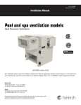
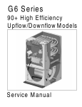
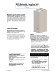
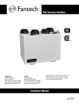
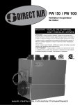
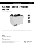
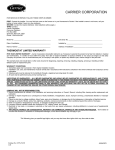
INSTALLATION
AND OPERATION
INSTRUCTIONS
P707
Dehumidistat
Part Number P707-MDEH1
SAFETY CONSIDERATIONS
cause of structure damage and IAQ problems such as mold
and mildew.
Installing, starting up, and servicing equipment can be hazardous due to system pressures, electrical components and
equipment location (roofs, elevated structures, etc.). Only
trained, qualified installers and service mechanics should
install, start up, and service this equipment.
When working on the equipment, observe precautions in the
literature and on tags, stickers, and labels attached to the
equipment.
INSTALLATION
NOTE: For technical assistance, call 1-800-747-1762.
To install the dehumidistat, perform the following
procedure:
1. Determine the mounting location for the dehumidistat.
Location should be in an easily accessible area. Do not
locate where humidity sensor could be affected by
direct humidity sources.
2. All controls are low voltage. Use 22 to 26 gage fieldprovided wire.
3. Connect two wires to the DEHUM terminals on ventilator. See Fig. 2. Polarity does not matter. Either wire
can be connected to either terminal.
4. Run wire to mounting location. Do not run control
wire with power wiring. Interference from power wiring can cause changes to control signal.
Before installation, always check to be sure main power to
systems are OFF. Electrical shock can cause personal
injury or death.
GENERAL
The MDEH1 dehumidistat is used with Totaline SHR series
heat recovery ventilators. See Fig. 1. The dehumidistat is used
to control the indoor humidity level. High humidity is a major
comfor t
de
ne
Zo
e
d
i
m
hu
us
sH
um
s humide
oin
•M
More H
Les
id
Co
um
m
id
f
•P
l
t
or
Fig. 1 — Dehumidistat
Manufacturer reserves the right to
discontinue, or change at any time,
specifications or designs without notice
and without incurring obligations.
REPLACEMENT COMPONENTS DIVISION
© CARRIER CORPORATION 2004 2-04
PRINTED IN U.S.A.
LITERATURE NUMBER P707-3SI
REPLACES: New
CATALOG NUMBER 570-330
OPERATION
5. The dehumidistat consists of two pieces, a mounting
plate and the cover. Remove cover from the mounting
plate. Pull wiring through the hole in the mounting
plate.
6. Connect wiring to the terminals on the mounting plate
of the dehumidistat. Two spade connector are provided
in the dehumidistat for wiring connections. See Fig. 3.
7. Mount the dehumidistat on the wall with the two
screws and wall anchors provided.
8. Snap on the cover on the mounting plate.
When the dehumidistat is installed, the humidity dial should
be set to the desired level. When the indoor humidity level at
the dehumidistat is exceeded, the ventilator will go into Override mode. Override mode will continue until relative humidity
drops below the set point of the dehumidistat.
It is not necessary to change the humidity setting every day.
To avoid window condensation, monitor the average weekly
temperature to find a comfortable level. Adjust the control
when needed.
DEHUMIDISTAT
EXTERNAL CONTACTS
ON VENTILATOR
DEHUM
WALL CONTROL
TIMER
+ -
Fig. 2 — Dehumidistat Wiring
Fig. 4 — Replacing Cover
Fig. 3 — Dehumidistat Terminal Connections
2
LIMITED TWO-YEAR WARRANTY
TWO-YEAR WARRANTY — This CARRIER CORPORATION product is warranted to be free from defects
in material and workmanship under normal use and maintenance for a period of two years from the date of
original installation. A new or remanufactured part to replace the defective part will be provided without
charge for the part itself, through a qualified servicing CARRIER CORPORATION dealer or service, PROVIDED the defective part is returned to our distributor. The replacement part assumes the unused portion of
the warranty.
THIS WARRANTY DOES NOT INCLUDE ANY ADDITIONAL LABOR ALLOWANCE OR OTHER COSTS
incurred for diagnosis, repairing, removing, installing, shipping, servicing, or handling of either defective
parts or replacement parts. SUCH COSTS MAY BE COVERED BY a separate warranty provided by the
installer.
LIMITATIONS OF WARRANTIES — ALL IMPLIED WARRANTIES (INCLUDING IMPLIED WARRANTIES
OF MERCHANTABILITY) ARE HEREBY LIMITED IN DURATION TO THE PERIOD FOR WHICH THE LIMITED WARRANTY IS GIVEN. THE EXPRESSED WARRANTIES MADE IN THIS WARRANTY ARE
EXCLUSIVE AND MAY NOT BE ALTERED, ENLARGED, OR CHANGED BY ANY DISTRIBUTOR,
DEALER, OR OTHER PERSON WHATSOEVER.
CARRIER WILL NOT BE RESPONSIBLE FOR:
1. Normal maintenance as outlined in the installation and servicing instructions or owner’s manual including
replacement of filters or bulbs.
2. Damage or repairs required as a consequence of faulty installation or application by others.
3. Failure to start due to voltage conditions, blown fuses, open circuit breakers or other damages due to the
inadequacy or interruption of electrical service.
4. Damage or repairs needed as a consequence of any misapplication, abuse, improper servicing, unauthorized alteration, or improper operations.
5. Damage as a result of floods, winds, fires, lightning, accidents, corrosive atmosphere, or other conditions
beyond the control of CARRIER CORPORATION.
6. Parts not supplied or designated by CARRIER CORPORATION.
7. CARRIER CORPORATION products installed outside the continental U.S.A., Alaska, Hawaii, and
Canada.
8. ANY SPECIAL INDIRECT OR CONSEQUENTIAL PROPERTY OR COMMERCIAL DAMAGE OF ANY
NATURE WHATSOEVER. Some states do not allow the exclusion of incidental or consequential damages, so the above limitation may not apply to you.
Model No.
Unit Serial No.
Date of Installation
Installed by
Name of Owner
Address of Installation
3
Manufacturer reserves the right to
discontinue, or change at any time,
specifications or designs without notice
and without incurring obligations.
REPLACEMENT COMPONENTS DIVISION
© CARRIER CORPORATION 2004 2-04
PRINTED IN U.S.A.
LITERATURE NUMBER P707-3SI
REPLACES: New
CATALOG NUMBER 570-330