1
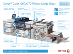
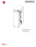
SM Pro Pucnher A1cover.qxp
11/29/2005
10:36 AM
Page 1
Professional
Puncher-A1
SERVICE
MANUAL
DU7-1175-000
NOVEMBER 2005
REV. 0
COPYRIGHT ©2005 CANON INC.
CANON Professional Puncher-A1 REV. 0 PRINTED IN U.S.A.
TABLE OF CONTENTS
1. INTRODUCTION............................................................................... 3
1.1 INTRODUCTION ............................................................................................ 3
1.2 PROFESSIONAL PUNCHER-A1 FAQ’S ....................................................... 3
2. INSTALLATION................................................................................ 5
2.1 UNPACKING................................................................................................... 5
2.2 UNIT SET-UP ................................................................................................. 5
2.3 UNIT OPERATION ......................................................................................... 5
3. MAINTENANCE................................................................................ 7
3.1 INSPECTION, CLEANING AND LUBRICATION ........................................... 7
3.2 DIE SET MAINTENANCE............................................................................... 8
3.3 PREVENTATIVE MAINTENANCE SCHEDULE ............................................ 9
3.4 SETTING THE RIGHT EXPECTATIONS....................................................... 9
4. ADJUSTMENTS AND SPECIAL PROCEDURES ......................... 10
4.1 TOOL RECOMMENDATIONS ..................................................................... 10
4.2 DIE SET POSITION CRADLE ADJUSTMENT, CENTERING PUNCHED
HOLES ................................................................................................................ 10
4.3 REMOVAL OF PUNCH MODULE................................................................ 13
4.4 GREEN BELT REPLACEMENT, ALIGNER PANEL REMOVAL,
EXPLANATION................................................................................................... 14
4.5 GREEN BELT REPLACEMENT, PAPER ENTRANCE SIDE ...................... 15
4.6 GREEN BELT REPLACEMENT, PAPER EXIT SIDE .................................. 21
4.7 BACK GAGE ASSEMBLY ............................................................................ 28
4.8 INSTALLATION STEPS ............................................................................... 28
4.9 TO CLEAR A PAPER JAM ........................................................................... 30
4.10 SOFTWARE UPDATE PROCEDURE........................................................ 31
5. TECHNICAL TROUBLESHOOTING.............................................. 32
5.1 THEORY OF OPERATION .......................................................................... 32
5.2 TROUBLESHOOTING GUIDE CHART........................................................ 34
5.3 ELECTRICAL SCHEMATIC ......................................................................... 37
6. OPERATING CONTROLS.............................................................. 37
6.1 PUNCHING PATTERNS .............................................................................. 37
6.2 CHANGING THE PUNCH DIE SETS........................................................... 37
6.3 PAPER CHIP DRAWER ............................................................................... 38
6.4 SERVICE ...................................................................................................... 38
7. SPECIFICATIONS .......................................................................... 40
7.1 SPECIFICATIONS, 115V & 230V PROFESSIONAL PUNCHER-A1 .......... 40
8. GLOSSARY OF TERMS ....................................................................
8.1 GLOSSARY OF TERMS ..................................................................................
2
1.
INTRODUCTION
1.1
INTRODUCTION
The Professional Puncher-A1 is an innovative solution for punching paper and
offers the following design features:
• Quick-change die sets that are self-latching without tools or levers.
• All Professional Puncher-A1 die sets include an Identifying Label providing user
with the hole pattern and name.
• Convenient storage area for three extra Die Sets located above the sheet bypass.
1.2
PROFESSIONAL PUNCHER-A1 FAQ’S
The CANON Professional Puncher-A1 will perform best when used for applications
that it was designed to perform. To ensure complete satisfaction, operate the
Professional Puncher-A1 within the following design parameters.
Professional 208V, 60Hz
(North America)
Professional 230/240V,
50Hz (Europe)
Sheet Sizes Supported:
Punching
Letter-21.59cm x 27.94cm
(29.74cm edge only)
A4-21.59cm x 29.74cm
(29.74cm edge only)
Bypass Mode (not punching)
5.5" x 8.5" upto 11" x 17"
supports all stocks and
weights that the printer
supports in bypass mode.
5.5" x 8.5" upto 11" x 17"
supports all stocks and
weights that the printer
supports in bypass mode.
Punching
75gsm (20lb Bond) to 216
gsm (80lb Cover)
75gsm (20lb Bond) to 216
gsm (80lb Cover)
Bypass Mode (not punching)
52 gsm (16lb Bond) to 216
gsm (80lb Cover)
52 gsm (16lb Bond) to 216
gsm (80lb Cover)
Physical Dimensions
12" width x 38.5" height x
28.5" depth
12" width x 38.5" height x
28.5" depth
Physical Weight
70kgs (154lbs)
70kgs (154lbs)
Shipping Weight
Power Consumption:
115.5kgs (254lbs)
115.5kgs (254lbs)
Power Supply
208V, 60Hz (Single Phase)
230/240V, 50Hz
(Single Phase)
Electrical
1.8A/1.7A, 240W, 1160
BTU/Hr
Paper Weights Supported:
1.8A/1.7A, 240W, 1160
BTU/Hr
3
8.5” x 11” (LEF) Only:
Professional Puncher-A1 is designed to punch this size only (LEF) no exceptions.
Attempting to punch a sheet size other than 8.5” x 11” (LEF) will cause a jam.
• Professional Puncher-A1 cannot punch tabs. Tabs will have to be run, punched
and inserted offline.
• Use a colored sheet insert (instead of the tab) in the job workflow for easier tab
insertion after the job has been run.
Die Sets:
The CANON Professional Puncher-A1 is capable of punching a variety of hole-punch
patterns by simply changing the Die Set. Die sets can be changed in seconds
without tools. The Die Sets currently available are listed below:
North America (Letter)
Europe (A4)
3-hole
4-hole / 2hole
Velo Bind 11-hole
Velo Bind 12-hole
CombBind 19-hole
CombBind 20 or 21
Wire Bind (2 types) Square
- 21-hole Wire Bind
- 32-hole Wire Bind
Wire Bind (2 types) Round
- 23-hole Wire Bind
- 34-hole Wire Bind
Color coil 44-hole (2 types)
- 44-hole RND
- 44-hole Oval
Color Coil 47 hole (2 types)
- 47-hole – RND
- 47-hole – Oval
Punch Pattern Samples (North America – Letter Shown)
4
2.
2.1
INSTALLATION
UNPACKING
UNPACKING
• Inspect the outside of the package for shipping damage. If there is evidence of
shipping damage, contact the shipping carrier immediately.
• Remove the punch from its shipping carton.
• Inspect for any concealed damage to unit. If there is evidence of concealed
shipping damage, contact the shipping carrier immediately.
• Remove all shipping tape from doors and levers.
2.2
UNIT SET-UP
Step One:
Step Two:
2.3
Connect the communication cable.
Connect the power cord.
UNIT OPERATION
• Check to ensure that the paper chip tray is securely in place.
• Check to ensure that a Die Set is installed properly and that any extra Die Sets are
securely stored in the Die Storage Area.
• Run a small test job in “Bypass” mode. Check to ensure that the job is not
punched and bypasses properly.
• Run a small job with Punch Enabled. Check the punched holes of the job.
5
CANON PROFESSIONAL PUNCHER-A1 DIE SET - INFORMATION SHEET
IMPORTANT NOTICE REGARDING THE DIE SETS PLEASE READ
Your CANON Professional Puncher-A1 die set (C4, W2 and W3 versions), is
supplied with a felt pad containing oil, a pad retaining magnet and shield*. Do not
throw these items away!
The felt pad will provide lubrication to the punch pins under normal usage and will
help to keep the punch pins clean. The magnet is intended to keep the felt pad in
place during typical handling. If the pad and magnet came off of this die set during
shipping or unpacking, please replace them as indicated in the accompanying
diagram.
Keep this sheet as a reference in the event that the pad and magnet are removed or
replaced.
FELT PAD
MAGNET
SHEILD
SHOULDER BOLT
WITH SPRING
Felt Pad and Retaining Magnet are not required or included with the 3-Hole, PB,
C4, ProClick® or VB die sets.
6
3.
3.1
MAINTENANCE
INSPECTION, CLEANING AND LUBRICATION
The following maintenance should be performed once annually, under normal use.
Operational Inspection
1. If operating properly, the Professional Puncher-A1 will punch the same types of
copy paper and cover materials handled by the copier/printer. It will run at the
speed of the printer.
2. Hole quality will vary between different grades of paper.
External Cleaning
1. Make sure you disconnect the Professional Puncher-A1 from its power source
before cleaning. The cover may be cleaned with a soft cloth moistened with mild
detergent and warm water.
2. Do not use chemical cleaners or solvents as these may have a harmful effect.
Use detergent sparingly to avoid contact with electrical components.
Internal Cleaning
Before internal cleaning, be sure to disconnect power to the Professional PuncherA1 and ensure that you retain control of the power cord.
Occasionally, it will be necessary to remove the rear cover and remove paper dust
built up around the motor and other electrical components. Use a vacuum cleaner if
possible. A small paintbrush can also be used but extreme care should be used
around electrical components.
Internal Inspection
Whenever the cover has been removed for corrective maintenance, visually inspect
for defects such as loose screws or nuts, abraded wire insulation, loose terminals,
etc. Correct any defects before returning the machine to service.
Lubrication Points and Recommended Lubricant
• Lubricate the punch pins and/or the felt pad once every 50,000-punch cycles with
oil (High Quality Machine Oil is recommended).
• Method:
1. Sparingly depress the Pin Guide so that the Punch Pins protrude from
the bottom plate, oil the ends of the pins and wipe clean.
2. Apply oil directly to the felt pad (If so equipped).
3. Apply two drops of oil to each of the two shoulder bolts and springs.
• If Punch Drive Module Assembly is ever removed for service, check for sufficient
grease on the cranks.
7
GREASING CRANKS
Die Sets
Professional Puncher-A1 Die Sets have an average expected life of approximately
500,000 sheets of paper. This life may vary depending on variables such as
following the lubrication schedule described above, the type of paper being punched,
the cover stocks being punched and the typical length of the average job.
3.2
DIE SET MAINTENANCE
Die sets have a minimum life expectancy of 500,000 cycles depending on
application, environmental factors and maintenance. Periodic lubrication of the
punch pins can extend the life significantly. CANON recommends use of a high
quality machine oil (do not use spray oils) every 50,000-punch cycles.
SHOULDER BOLT
W ITH SPRING
SPRING
LU
BR
IC
AT
E
TH
E
PI
NS
The die set cannot be repaired or adjusted.
Other than lubrication, if a Die set is damaged or worn, the Die set should be
replaced.
8
3.3
PREVENTATIVE MAINTENANCE SCHEDULE
The following preventative maintenance should be performed during the regular
printer inspection intervals.
• Disconnect the main cord set and retain it in your control for your safety.
• Remove the rear cover.
• Perform a visual inspection; clean, adjust and replace components as required.
• Vacuum Paper Chad out of Back Gage Mechanism and Die Guide as well as
base.
• Optical Sensors; Remove dust and particles from the lens using a soft cloth.
• Inspect Timing Belts for wearing or fraying.
• Inspect any Latching Mechanisms, clear any jams paper debris.
• Inspect Left / Right Punch alignment by running paper with each die set, check for
even hole alignment by folding the paper in half. If adjustment is required, ensure
that the Die Latch is properly adjusted.
• Inspect the Door closing latch for proper alignment, if bent, instructs the operator
to avoid closing the door with paper path latches out of place.
• Lubrication of the Die Set Pins (see note above)
• Cams (when punch is pulled), lubricate with high quality grease
• Inspect the Idler Rollers, clean if necessary.
• Inspect the Drive Rollers, clean if necessary.
• Inspect the Paper Path Panels, clean if necessary.
• Inspect each Die Set for wear. Run at least 100 sheets of paper. Look for signs of
excess paper jamming. Inspect the hole quality. Hanging chad or ragged holes can
lead to paper jams. If the hole is cut sharp enough that there is no hanging chad
and the paper passes through the system without catching and jamming, the die
set still has life.
As with any electro-mechanical device, isolated component failures may occur.
3.4
SETTING THE RIGHT EXPECTATIONS
Product Positioning:
Professional Puncher-A1 provides a flexible, cost effective punching solution for light
to medium level production oriented customers.
• Designed for customers that have the need to punch their documents at a
maximum of 60-70% of their overall workflow.
• Recommended punching limit to 200k sheets per month. (600k sheets in
bypass mode)
• Die Sets will decrease in performance over time based on the types of stocks and
weights that are being punched.
• CANON guarantees a minimum of 500k punches per die set. However, if
paper stock punched is typically 20lb bond, then up to 2 million punches can
be achieved.
• Should be regarded as a long-term supply item.
9
4.
4.1
ADJUSTMENT AND SPECIAL PROCEDURES
TOOL RECOMMENDATIONS
What you need to service the CANON Professional Puncher-A1:
1. Standard Measure Tools (English as opposed to metric)
a. Open End Ignition Wrench – ¼” (required only for Chad Kit installation)
b. Open the End Wrench 9/16”(for adjustable casters)
c. Nut Driver, 5/16”
d. Nut Driver, ¼” (see note below)
e. Allen Wrench, 3/32” (comes with Chad Control Kit)
f. Allen Wrench, 5/64”
g. Allen Wrench, 9/64”
2. Other recommended tools
a. Needle Nose Pliers (Side Cutters)
b. Wire Cutters
c. Screw Driver, Phillips Head
d. Screw Driver, Flat Head, Small
3. Supply of Wire Tie Wraps
NOTE: A nut driver head of ¼” is the most common size for the barrel of a
Magnetic or interchangeable tip screwdriver.
4.2
DIE SET POSITION CRADLE ADJUSTMENT, CENTERING
PUNCHED HOLES
The die set position cradle is set in the factory; however, because of the punchedhole spacing on the PB die sets, there is a minimal amount of paper on each edge of
the punched paper. The die set position cradle may have to be fine adjusted to
center the punched-hole pattern in the paper.
Listed below are the step-by-step instructions to adjust the die set to the proper
position:
• The punched-hole alignment must be checked on a piece of punched paper. Fold
the punched sheet of paper in half and the punched-holes should be aligned. If the
punched-holes are not aligned, then the die set cradle must be adjusted to align
the punched holes.
NOTE: The paper path is always constant, if the holes are not centered; you
must adjust the die set cradle.
10
PUNCHED HOLE ALIGNMENT CHECKING
• The back cover on the Professional Puncher-A1 must be removed to access the
die set position cradle.
CRADLE
• Before adjusting the die set position cradle, you must first note what direction the
die set cradle must move.
• Before you adjust the die set position cradle, you must loosen the lock-down
screw.
11
PRESS HERE
TO TILT
ADJUSTMENT
SCREW
LOCK-DOWN
SCREW
LOOSEN
SCREW
• Observe the punched paper; if the punched-holes are too close to the rear of the
machine, then you must turn the adjustment screw counter-clockwise.
TURN COUNTERCLOCKWISE
• If the punched-holes are too close to the front of the machine, then you must turn
the adjustment screw clockwise.
12
TURN
CLOCKWISE
• Using a flat-head screwdriver, turn the adjustment screw clockwise or counterclockwise to move the die set position cradle.
NOTE: Seven full turns of the adjustment screw result in a ¼” change in the
punched hole position.
• Before tightening the lock-down screw, tilt or bias the assembly towards the
bottom of the machine and tighten the lock-down screw. This will ensure positive
engagement between the locking lever and the die set.
TILT TO BOTTOM
OF M/C
TIGHTEN
SCREW
• Run a test sample of punched paper and recheck paper alignment. Re-adjust if
necessary.
4.3
REMOVAL OF PUNCH MODULE
1. Examine the Drive Belts. Note the consistency in tightness of the belts. They
should all have approximately ¼” of deflection; remove the four drive belts items
1, 2, 3, 4.
Disconnect the Sensor Wire Connection
13
2. Remove 4 screws in front and 2 in back
3. Cut any wire ties that may prevent freedom of movement to slide the Punch
Module (A) outward
4. Remove the Back Gauge Assembly (B).
5. Remove the black Knob (C) at the front (customer side) of the Punch Module
Drive Shaft.
A
C
FRO NT SIDE
B
6. Slide the Punch Module unit part way out to reach and unplug the Punch Sensor
Harness (Red, Black, White wires)
7. Slide the entire Punch Assembly (C) out and lay it beside the Professional
Puncher-A1. Take care not to damage wires or Rollers as you do so.
8. Lubricate the Drive Cams sparingly of the punch module using a multi-purpose,
extreme pressure lubricant, preferably formulated with Teflon.
Note: This lubrication is not required during the normal life but is reasonable to do
this of the module every needs service.
9. To replace any component of the punch Module, disassemble components as
required
4.4
GREEN BELT REPLACEMENT, ALIGNER PANEL REMOVAL,
EXPLANATION
The following procedure explains how to remove the Entrance Side Aligner Panel
and the Exit Side Aligner Panel.
The basic intent of this procedure is to access and replace the Green Aligner Belts,
but once you know how to follow this procedure you are now able to access other
components as well.
SYMPTOM
Paper will stop moving through the Punch paper path.
CAUSE
One or both of the Green Aligner Belts have broken. If this break occurs, it would
usually occur at the Weld Splice.
14
PROCEDURE TO REPLACE ALIGNER BELTS
Replacement of the Green Belt from the Aligner, Paper Entrance Side.
Replacement of the Green Belt from the Aligner, Paper Exit Side.
4.5
GREEN BELT REPLACEMENT, PAPER ENTRANCE SIDE
The following step-by-step directions inform you how to remove and then assembly
the components necessary to access the Paper Entrance Side Aligner Green Belt,
P/N FC3-3633-0000
It will help you to reference your Professional Puncher-A1 Service Manual part
drawings as you follow this process.
Special Tools Required:
• Twelve inch metal ruler or similar straight edge.
• Phillips Head Screw Driver 7” or less in total length.
• Alan wrenches (5/64” & 9/64”).
• Nut Driver (1/4” & 5/16”)
• Rare Earth Magnet Snake Neck (optional – good for retrieving any hardware that
happens to fall in hard to reach spots)
• Snap Ring pliers
• E-Ring tool
NOTE: During assembly, be sure not to over tighten any of the mounting
screws.
Step 1:
Step 2:
Step 3:
Step 4:
Step 5:
Disconnect the Professional Puncher-A1 from Power. Retain the power
cord in your possession for your safety.
Disconnect the Communication Cable to the Finisher.
Unlatch the CANON Professional Puncher-A1 from both the Finisher and
the Printer.
NOTE: You must first remove the screw that secures the latch in place
(if so equipped).
Open the Front Door (A) of the Professional Puncher-A1.
Remove the Paper Chip Tray (B), empty it and replace it. This is to
prevent difficulty in finding any small parts that you may drop into the
chad
15
A
BINDER SIDE
B
Step 6:
To remove the Rear Cabinet/Cover (C) of the Professional Puncher-A1,
1. Remove the “5” screws on Exit side and “3” screws on Entrance side.
2. Slide the Rear Sheet Metal Cabinet/Cover off of the Professional Puncher-A1.
NOTE: You do not need to lift upward and you do not need to remove the Top
Cover.
Step 7:
Disconnect the Entrance Sensor Wire from the Side Frame.
Step 8:
Remove the “4” screws that secure the Front Paper Chute (D), set aside.
Step 9:
To remove the J2 Flipper, Door Latch (E).
A. Unhook the spring of the J2 Flipper on the right end.
B. Remove only one (the one closest to the frame) of the “E” Rings of
the J2 Flipper on the left end (front Door side).
C. Push the J2 Flipper in toward the front Door until it clears the rear
frame.
D. Pull the entire J2 Flipper, Door Latch out and set it aside.
Step 10: Remove the “4” screws that secure the Docking Bracket (F). Remove,
and set aside.
FRONT DOOR
D
E
16
Step 11:
To remove Entrance Aligner Panel, Idler Paper Guide Assembly
(item 19)
A. Remove “2” E-Rings from the Pivot Shaft (G).
B. Slide the Shaft (G) all the way out through the front of the
Professional Puncher-A1.
C. Remove the Fan (H) that prevents access to the Flexible Cable. To
remove it simply pull it off of the Shaft.
D. Remove the Flexible Cable using an Alan Wrench.
E. Remove the rear top Pulley (I).
F. Loosen the Belt Idler (J).
G. Remove the Belt and Pulley.
H. Loosen screw from the Solenoid Link.
I. Remove the Solenoid Assembly (K) and link from the Diverter
Shaft, leave it hang.
J. Remove the two E-Rings of the Entrance Diverter Assembly, slide
the Diverter out and set it aside.
Step 12:
To remove the Drive Side, Paper Entrance Guide Aligner Assembly (L),
which is the large sheet metal Assembly that actually, containers the
Green Belt and Aligner.
A. Remove the “6” Screws that secure the face of this Assembly.
E. Remove the “2” screws that secure this Assembly from the Side
Frame.
F. Pull and walk the entire sheet metal assembly of the Paper Guide
Aligner Assembly up and outward. You can grab the Assembly at
the Roller cut out with your fingers.
IMPORTANT:
As you do this, disconnect the Sensor harness behind the
Assembly as soon as you are able to reach it.
G
K
L
Step 13:
I H
Before you remove the Green Belt Aligner Roller Assembly from the
sheet metal paper guide, observe the perfectly flush surfaces of the
Green Belt Aligner Roller Assembly to the sheet metal surface of the
Rear, Drive Side, and Paper Guide Aligner Assembly. Hold a straight
edge like a 12”metal ruler across the surface of the sheet metal face
17
and the metal (w/o a belt) Green Belt Aligner Roller itself. Note that the
two metal surfaces are flush.
Step 14:
Remove the Green Belt Aligner Roller Assembly by removing the “4”
screws (S).
Important: Leave the Flex Shaft (FS) attached.
Step 15:
Stretch the new Belt (B) onto the Aligner Roller Assembly, green side
out. Rotate the Shaft (S) to confirm that the belt tracks properly.
S
B
STRETCH
FS
Slide the Aligner into place, loosely attach the “4” Pan Head Screws with
the “4” Lock Washers.
Check that the metal surface of the Aligner Roller Assembly is flush with the Sheet
Metal surface of the Paper Guide. A 12” metal ruler works well to check this
adjustment. Slip the ruler under the green belt and press it flat against the two
surfaces. Adjust the Aligner and snug the screws when perfectly flush.
NOTE: The green belt should look like the drawing shown after step 11.
As a double check, hold the entire Paper Guide assembly up so that you can visually
inspect the alignment between the sheet metal surface and the metal surface of the
Aligner. The Green Belt should appear to be even or parallel, and just floating above
the surface of the sheet metal.
Step 16:
18
Step 17:
To install the Paper Guide Assembly into the Professional Puncher-A1.
1. As you slide the Paper Guide Assembly into place,
a. Hook up the Sensor Harness to the Sensor on the back.
b. Lift it up slightly to clear the lower Transition Paper Guide.
c. Be sure to clear the Sensor Bracket at the top left.
d. Be sure that the Flex Coupling Shaft is sticking out of the rear of the
Professional Puncher-A1 properly.
2. Visually check all around the mounting area of the Paper Guide Assembly and
that the Sensor Harness is properly connected.
3. Loosely secure it in place with “3” screws on the left and “3” on the right.
4. Loosely install the “2” top screws.
5. Once all “8” mounting screws have been properly started you have good
alignment. You may now go back and tighten the screws until they are snug.
SENSOR
FLEXIBLE
SHAFT
ALIGN & FIX
SCREWS
Step 18:
Step 19:
Step 20:
Install the Flexible Shaft (item 5).
Install the curved sheet metal Exit Paper Guide (item 7) with Idler Roller
“4” Screws.
Start all “4” screws, (2 on front and 2 on back) then tighten.
Connect the Sensor Wire Harness at the top rear of the Exit Paper
Guide.
19
Step 21:
Install the J2 Shaft back into place by inserting it first into the front, then
the back.
INSTAL J2 SHAFT
Step 22:
Close the J2 Flipper Latch.
Repeat the test of rotating the pulleys to ensure smooth rotation of the
Idler Rollers.
Step 23:
Attach the J2 Shaft Spring. Install the front E-Ring to secure J2.
Step 24:
To install the Idler Aligner Paper Guide.
A. Hold it loosely in place.
B. Press the Nylon Flange Bearings into place, through both pieces of
sheet metal, with the Flange to the inside.
C. Slide the Shaft through the front of the machine, while holding the
Nylon Flange Bearing in place.
D. Secure with “2” E-Rings on the inside of the bearing.
E. Inspect by pressing in on the bottom area of the sheet metal for:
#1 should see a slight deflection of each Idler Roller as you press,
#2 as you press, you can turn the Pulley’s at the rear of the
Professional Puncher-A1 and see the Idler Rollers rotate smoothly.
Step 25:
Attach the Docking Plate using “4” Screws.
Step 26:
Attach the Back Rear Cover using the 7 screws (2 for the Entrance and
5 for the Exit side).
Test the Professional Puncher-A1 by running 10 copies in bypass mode,
Then 1 sheet in punch mode,
Then 10 sheets in punch mode,
Then 100 sheets in punch model
This entire process takes approximately 60 minutes. First time maybe a little longer.
20
AFTER ASSEMBLY
4.6
GREEN BELT REPLACEMENT, PAPER EXIT SIDE
The following step-by-step directions inform you how to remove and then assembly
the components necessary to access the Paper Exit Side Aligner Green Belt,
P/N FC3-3633-0000
It will help you to reference your Professional Puncher-A1 Service Manual part
drawings as you follow this process.
Special Tools Required:
• Twelve inch metal ruler or similar straight edge.
• Phillips Head Screw Driver 7” or less in total length.
• Alan wrenches.
• Nut Driver
• Rare Earth Magnet Snake Neck (optional – good for retrieving any hardware that
happens to fall in hard to reach spots)
• Snap Ring pliers
• E-Ring tool
NOTE: During assembly, be sure not to over tighten any of the mounting
screws.
Step 1:
Disconnect the Professional Puncher-A1 from Power. Retain the power
cord in your possession for your safety.
Step 2:
Disconnect the Communication Cable to the Finisher.
Step 3:
Unlatch the CANON Professional Puncher-A1 from both the Finisher and
the Printer.
NOTE: You must first remove the screw that secures the latch in place
(if so equipped).
Step 4:
Open the front door (A) of the Professional Puncher-A1.
21
BINDER SIDE
A
Step 5:
To remove the Rear Cabinet/Cover (B) of the Professional Puncher-A1,
1. Remove the 5 screws on Exit side and 2 screws on Entrance side.
2. Slide the Rear Sheet Metal Cabinet/Cover off of the Professional Puncher-A1.
NOTE: You do not need to lift upward and you do not need to remove
the Top Cover.
B
Step 6:
To remove the J2 Flipper (C), Door Latch.
A. Remove only one (the one closest to the frame) of the “E” Rings of
the J2 Flipper on the right end (front Door side).
B. Push the J2 Flipper in toward the front Door until it clears the rear
frame.
C. Pull the entire J2 Flipper, Door Latch out and set it aside.
22
Step 7:
Unhook spring from the Docking Plate (D) and Door. Remove the “4”
screws that secure the Docking Bracket. Remove, and set aside.
PAPER ENTERANCE
SIDE
FRONT DOOR
SIDE
PAPER EXIT
SIDE
Step 8:
To remove the Rear Aligner, Idler Paper Guide Assembly
A. Remove “2” E-Rings from the Pivot Shaft.
B. Slide the Shaft all the way out through the front of the Professional
Puncher-A1.
C. Remove the “2” Nylon Bearings.
Step 9:
D. Remove and set aside the Rear Aligner, Idler Paper Guide
Assembly.
To remove the curved sheet metal Exit Paper Guide Assembly
A. Remove the “4” Screws (2 rear and 2 front) of the curved sheet
metal Exit Paper Guide Assembly
B. Unplug the Sensor
C. Pull the entire sheet metal Exit Paper Guide Assembly out, set
aside.
23
Step 10:
To remove the Rear, Drive Side, and Paper Guide Aligner Assembly.
This is the large Sheet Metal Assembly within the Professional PuncherA1 that actually contains the Green Belt Aligner itself.
IMPORTANT: Walk the Belt off of the Aligner Pulley at the rear.
A. Remove the “2” screws that hold the Block to the Frame. Now – the
Coupler is loose and the Rear Panel will come out.
B. Remove the “6” Screws that secure the face of this Assembly.
C. Remove the “2” Screws that secure this Assembly from the top.
D. Pull and walk the entire sheet metal assembly of the Paper Guide Aligner
up and outward. You can grab the Assembly at the Roller cut out with your
fingers.
NOTE:
NOTE:
The Helical coupling is very delicate, be gentle.
In order to access these screws, you must first remove the Die Set
Storage Shelf and the Cable Shield attached to the Die Storage Shelf
at the paper entrance side. Moving the Die Storage Shelf aside will
enable better access to the “2” screws with a short (7” or less) Phillips
Screw Driver.
ALIGNER DRIVE
BELT ASSY
Step 11:
E. Bend in the Tab of the frame near the middle, front area to allow
enough clearance to work the sheet metal Paper Guide Aligner
Assembly out.
IMPORTANT: As you do this, disconnect the Sensor harness behind
the Assembly as soon as you are able to reach it.
Before you remove the Green Belt Aligner Roller Assembly from the
sheet metal paper guide, observe the perfectly flush surfaces of the
Green Belt Aligner Roller Assembly to the sheet metal surface of the
Rear, Drive Side, Paper Guide Aligner Assembly. Hold a straight edge
like a 12”metal ruler across the surface of the sheet metal face and the
24
metal (w/o a belt) Green Belt Aligner Roller itself. Note that the two metal
surfaces are flush.
Step 12:
Remove the Green Belt Aligner Roller Assembly by removing the “4”
screws.
Important: Leave the Coupler attached.
Assembly Process
Step 13: Stretch the new green belt onto the Aligner Roller Assembly, green side
out.
• Take care when handling the Aligner Roller Assembly so as not to
damage the Flex Coupling.
• Rotate the shaft to confirm that the belt tracks properly.
Step 14: Slide the Aligner into place, loosely attach the “4” Pan Head Screws with
the “4” Lock Washers.
ROTATE
STRETCH
BELT
Check that the metal surface of the Aligner Roller Assembly is flush with the Sheet
Metal surface of the Paper Guide. A 12” metal ruler works well to check this
adjustment. Slip the ruler under the green belt and press it flat against the two
surfaces. Adjust the Aligner and snug the screws when perfectly flush.
NOTE: The green belt should look like the drawing shown after step 11.
25
As a double check, hold the entire Paper Guide assembly up so that you can visually
inspect the alignment between the sheet metal surface and the metal surface of the
Aligner. The Green Belt should appear to be even and just floating above the surface of the
sheet metal.
ALIGN
& FIX SCREWS
Step 15:
To install the Paper Guide Assembly into the Professional Puncher-A1.
ASSEMBLE BACK
A. As you slide the Paper Guide Assembly into place,
a. Hook up the Sensor Harness to the Sensor on the back.
b. Lift it up slightly to clear the lower Transition Paper Guide.
c. Be sure to clear the Sensor Bracket at the top left.
d. Be sure that the Flex Coupling Shaft is sticking out of the rear of
the Professional Puncher-A1 properly.
B. Visually check all around the mounting area of the Paper Guide
Assembly and that the Sensor Harness is properly connected.
C. Loosely secure it in place with “3” screws on the left and “3” on the right.
D. Loosely install the “2” top screws. A useful tip might be to secure the Screw
to the tip of your Screwdriver with a small piece of masking tape to assist
you in finding the hole.
26
Step 16:
Step 17:
Step 18:
Step 19:
Step 20:
Step 21:
Step 22:
Step 23:
Step 24:
Step 25:
Step 26:
Step 27:
Step 28:
E. Once all “8” mounting screws have been properly started you have
good alignment. You may now go back and tighten the screws until
they are snug. Do not over tighten the “2” screws on top!
Install the “2” Screws to secure the Bearing Block for the Pulley
arrangement at the rear of the Professional Puncher-A1. Press the block
to the top of the punch before tightening
Install the Pulley and Belt onto the Pulley Block. Once properly aligned,
check Belt and Pulley movement. Tighten the Set Screw.
Install the Die Set Storage Rack with “3” screws front and “3” screws
back. Remember to attach the Ground Strap at the middle screw on the
rear (belt side). Start each screw to achieve proper alignment, then go
back over each screw and tighten it.
Install the Cable Guard on top of the Die Set Storage Rack (“2” Screws).
Install the curved sheet metal Exit Paper Guide with Idler Roller “4”
Screws.
Start all “4” screws, (2 on front and 2 on back) then tighten.
Connect the Sensor Wire Harness at the top rear of the Exit Paper
Guide.
To install the Idler Aligner Paper Guide.
A. Hold it loosely in place.
B. Press the Nylon Flange Bearings into place, through both pieces of
sheet metal, with the Flange to the inside.
C. Slide the Shaft through the front of the machine, while holding the
Nylon Flange Bearing in place.
D. Secure with “2” E-Rings on the inside of the bearing.
E. Inspect by pressing in on the bottom area of the sheet metal for:
#1 should see a slight deflection of each Idler Roller as you press,
#2 as you press, you can turn the Pulley’s at the rear of the
Professional Puncher-A1 and see the Idler Rollers rotate smoothly.
Bend the small metal tab back into place.
Install the J2 Shaft back into place by inserting it first into the front, then
the back.
Close the J2 Flipper Latch.
Repeat the test of rotating the pulleys to ensure smooth rotation of the
Idler Rollers.
Attach the J2 Shaft Spring
Install the front E-Ring to secure J2.
Attach the Docking Plate using “4” Screws and install spring from Plate
to Door.
Attach the Back Rear Cover using the 7 screws (2 for the Entrance and 5
for the Exit side).
Test the Professional Puncher-A1 by running 10 copies in bypass
mode,
Then 1 sheet in punch mode,
Then 10 sheets in punch mode,
Then 100 sheets in punch model
27
This entire process takes approximately 60 minutes. First time maybe a little longer.
AFTER ASSEMBLY
4.7
BACK GAGE AND CHAD CONTROL MECHANISM ADJUSTMENT, ASSEMBLY / DISASSEMBLY PROCEDURE
The Back Gage with Chad Control Mechanism is available as a kit service.
General Description:
The Professional Puncher-A1 Chad Control Mechanism directs Paper Chad into the
Chad Disposal Container, significantly reducing the amount of Chad that could flow
through the paper path. There will be some Chad that falls outside the Chad
Container. For example, when the customer changes their Die Set, some Chad
always comes with the Die and falls to the bottom of the machine or to the floor. As a
general practice, it is a good Preventative Maintenance practice to vacuum the inside
of the Professional Puncher-A1 periodically.
What you need to install this kit:
•
•
•
•
•
•
•
•
•
Open End Ignition Wrench – ¼”
Nut Driver, 5/16”
Nut Driver ¼”
Needle Nose Pliers (Side Cutters)
Allen Wrench (for 4-40 SHS – 3/32”)
Wire Cutters
Wire Tie Wraps (Qty. 5)
Screw Driver, Phillips Head
Screw Driver, Flat Head, Small
4.8
Contents of Kit:
•
•
•
•
Back Gage #7706972
E-Prom #7706791, 7706799
Brush #7706711
Holder #7706476
INSTALLATION STEPS
Step 1:
Step 2:
Disconnect power and communication cable.
Open door and remove Die Set, chad bin, and rear cover (opposite the
door).
28
NOTE:
Step 3:
Step 4:
Step 5:
Once you remove the screws that secure the rear cover, it will slide out
from under the top cover. You do not need to remove the top cover.
Remove the two screws holding the Die rail at the front of the
Professional Puncher-A1.
Remove the four screws holding the Die rail at the rear of the
Professional Puncher-A1.
Remove the wire that attaches the solenoid to the PC board. After all the
screws and the wire are removed you can now remove the back gage
and rail as an assembly.
BACK GAUGE ASSY
FRONT SIDE
Step 6:
Step 7:
Facing the back gauge pull the rail from the right side first and slide out
the assembly.
Install the chad bin.
29
Step 8:
Install the die set. Test the Professional Puncher-A1 system running first
one page at a time, then two pages then 5 pages, then 10 pages and
lastly run 50 test pages.
Step 9:
Replace the cover and run a few more test jobs.
Step 10: Skew Adjustment: Check for proper Hole alignment to paper edge.
The back gage is designed to give you some adjustment when the three screws are
loosened.
It will give you up and down play, which allows you to remove skew.
The ideal situation is to have the back gage all the way to the top position.
If not, paper can slip past the paper stops and give you a deep punch. This may
occur if the back gage is tightened into place in it’s bottom most position. This
situation is most likely to occur when using the VeloBind or PB die sets, which are at
one end of the Back Gage tolerance spectrum.
Three-Hole Die Set: At the other end of the Back Gage tolerance is the Three-Hole
Die Set. If the customer owns a Three-Hole Die, check this die to see if it is easy to
insert and remove. If the die is too tight you will need to lower the back gage slightly
to achieve the tightness you desire, while still retaining the PB and VeloBind
functionality mentioned above.
Now you need to run some paper and check for skew, at this point you can now use
the three screws to adjust skew if needed. After the adjustment is made re test with
the three-hole die. If all is well re test with the VeloBind die to make sure there are no
deep punches.
Step 11: Back Gage Adjustment to eliminate Deep Punching: Check for proper
operation with PB Die Set: In some cases, using a PB Die Set, you may
have an occurrence of a “Deep Punch” symptom. If this shows up during
testing, loosen the three main screws that secure the entire Back Gage
Assembly, push the entire mechanism upward, taking up all play, tighten
the three screws securely. Test approximately 200 to 500 sheets of
paper through the PB die. Check for no deep punching and no paper
jamming in the Die Set area
4.9
TO CLEAR A PAPER JAM
To clear a jam, first press the stop button on the printer, then check the printer
screen to see the area of the jam.
If the jam is in the printer or finisher only, follow the information on the screen to
clear the jam.
If the screen shows a jam in the punch, try to follow this sequence.
1. Open punch door.
2. Turn off the power
3. Turn punch knob J3 to home position.
4. Open top cover J1.
5. Open front paper door lever J2.
6. Open exit paper door lever J8.
7. Open bottom U-channel J7 by pressing in lever J6 and lower.
30
8. Clear paper from all these areas by turning knobs as shown.
9. When all the paper is cleared turn on power shut the door make sure the jam
light is out if not go back to step 1. And find the paper that is not clear.
10. When all the paper is cleared from the punch and the light is out follow the steps
used above to clear the printer and finisher.
11. Hit the punch green button and then the resume button on the printer, operation
should start.
12. If by chance you do not hit the green button the punch will go into bypass mode
at this time you will have to hit the stop button on the printer hit the green button
on the punch then the resume button on the printer.
13. This is only my way to clear a jam after you become more familiar with the punch
this procedure can change to your own refinement.
4.10 SOFTWARE UPDATE PROCEDURE (VERSION 10)
SOFTWARE UPDATE PROCEDURE (Version 1.0)
Tools Required:
• USB to DB9 female crossover cable.
• Computer with USB port and Hyper Terminal Software
• Download new firmware for installation and bootload.ht setup file.
Remove plastic cover from 9 pin connector on back of Professional Punch A1
Connect cable from computer to this 9 pin connector.
Run Hyper Terminal software.
From Hyper Terminal File Tab
Open: bootload.ht
From Hyper Terminal Screen
Press ENTER Key on Keyboard
Press V for current software version number
From Hyper Terminal Transfer Tab
Select Send Text File
Select new *.hex file to install
Numbers under the BOOTLOADER> prompt will increment as the download
continues.
When finished, press V on keyboard to display the new version number
Then press G on keyboard to install new software
When BOOTLOADER> prompt returns, the new software is installed.
Disconnect cable
Restart Professional Puncher A1
31
Following the steps above, the Hyper Terminal Screen should look like this:
BOOTLOADER>V
Professional Puncher A1
Ver.: XX.XX
BOOTLOADER> Downloading ...
0xF00000
Successful download of Professional Punch A1
Ver.: XX.XX
Begin downloading .hex file or enter a command listed below in <>:
<G>o execute the new downloaded code or display code <V>ersion
BOOTLOADER>V
Professional Puncher A1
Ver.: XX.XX
BOOTLOADER>G
Executing Professional Puncher A1
Ver.: XX.XX
Press <Enter> to run Bootloader or <ESC> if machine is always BUSY
If using a USB to Serial Cable with cable software installed: (Preferred
Method)
Load Windows Application file: Hyper Terminal.
From Hyper Terminal File Tab:
Open: boot load.ht
From Hyper Terminal Screen
Press Enter Key:
Press V for current software version number and name
BOOTLOADER>V
Pro Punch A1
Ver.: 04.14
Select Hyper Terminal Transfer Tab:
Send Text File
Select file MID_0414.hex or MID_0415.hex
BOOTLOADER> Downloading ...
0xF00000 (Note: This value will increment as the download continues)
Successful download of Professional Punch A1
Ver.: 04.15
Begin downloading .hex file or enter a command listed below in <>:
<G>o execute the new downloaded code or display code <V>ersion
Press V for version number (must be CAPITAL LETTER)
BOOTLOADER>V
Professional Punch A1
Ver.: 04.15
BOOTLOADER>G
Press G to install new code (must be CAPITAL LETTER)
32
Executing Professional Punch A1
Ver.: 04.15
Press <Enter> to run Bootloader or <ESC> if machine is always BUSY
New Software is installed
Disconnect cable
Restart Professional Punch
The yellow items are commands typed by the user to run the boot loader.
The green items are the responses from the boot loader in the Hyper Terminal
window.
Following the steps above, the Hyper Terminal Screen should look like this:
BOOTLOADER>V
Pro Punch A1
Ver.: 04.14
BOOTLOADER> Downloading ...
0xF00000
Successful download of Professional Punch A1
Ver.: 04.15
Begin downloading .hex file or enter a command listed below in <>:
<G>o execute the new downloaded code or display code <V>ersion
BOOTLOADER>V
Professional Punch A1
Ver.: 04.15
BOOTLOADER>G
Executing Professional Punch A1
Ver.: 04.15
Press <Enter> to run Bootloader or <ESC> if machine is always BUSY
The proper settings for the serial port for boot loader communications are:
Port:
BPS
Bits
Parity
Stop
Flow
COM5
19200
8
None
1
XON / XOFF
33
5.
TECHNICAL TROUBLESHOOTING
5.1
THEORY OF OPERATION
The CANON Stream Punch is a machine that punches various die set hole patterns
into single sheets of paper. The machine is placed between a printer / copier and a
finisher. There are two paper paths. One is the bypass section, which does not
punch paper. The other is the punch path. The punch path can be selected by
pressing the green button on the top of the Stream Punch.
The Stream Punch consists of several input / output devices to operate the machine
functions. The system intelligence is a Microchip micro-controller PIC17C752. The
present code is written in Microchip assembler. The list of I/O devices is:
Refer to the electrical wiring information, when reading the following material.
INPUTS:
Sensor 1
Sensor 2
Sensor 3
Sensor 4
Sensor 5
Sensor 6
Sensor 7
Sensor 8
Sensor 9
Switch 1
Switch 2A
Switch 2B
Switch 3
Switch 4
Optical
Optical
Optical
Optical
Optical
Optical
Optical
Optical
Optical Vane
Keypad
Mechanical
Mechanical
Mechanical
Mechanical
Starts machine motors, Sheet speed measurement, Jam detect
Stepper 1 control, Sheet speed measurement, Jam detect
Punch mechanism control, Backstop raiser, Jam detect
Jam detect at entrance of U-Channel
Jam detect at exit of U-Channel
Stepper 2 Control, Jam detect
Exit sensor, Jam detect
Bypass sensor, Sheet speed measurement, Jam detect
Monitors rotation of punch mechanism, Controls clutch and brake
Selects punch mode
Interlock Voltage, no machine movement if door is open
Door open signal
Chip tray switch
Die Set switch
OUTPUTS:
Diverter
Brake
Clutch
Backstop
Transport
Punch
Stepper 1
Stepper 2
DC Solenoid
DC Brake
DC Clutch
DC Solenoid
AC Motor
AC Motor
PWM Signal
Winding
PWM Signal
Winding
Diverts paper from bypass to punch sections
Stops the punch mechanism, keeps it in correct position
Clutches the punch mechanism to drive through paper
Provides stop for paper to rest against during punching
Provides paper movement through machine
Provides power to punch the paper
Controls Stepper Motor 1
On / Off signal for stepper holding current
Controls Stepper Motor 2
On / Off signal for stepper holding current
PRINTER COMMUNICATION:
Punch
Input
Motor
Jam
Input
Output
Tray /
Die
Output
Printer turns on Punch enabled mode (not presently
operational)
Printer turns on Stream Punch Motor
Punch signals a jam or the door is open (no operation
allowed)
Punch indicates tray or die set missing (bypass only
allowed)
34
SERIAL EEPROM CONTROL:
1 Input
3 Outputs
Counts number of punches for die set full, Saves value
For the Stream Punch to operate, all optical sensors must be clear. Any blocked
sensor or open door will prevent operation. The machine may operate in bypass
mode with or without a chip tray or die set. Both of these must be present to punch.
Stepper #1 Control:
If punch is not enabled, the Professional Puncher-A1 will run in bypass mode (no
punching). Either the printer or the first sheet entering the machine will turn on both
stepper motors. The time is measured for the leading edge of the first sheet to pass
sensor 8. Knowing the distance between sensors and the time it takes for the sheet
to pass both sensors, we can determine the speed of the paper. The time is
compared to a list and Stepper 1 and stepper 2 are adjusted to closely match the
incoming speed.
If the punch is enabled, the backstop is raised, the brake is engaged, and both the
transport and punch motors are started. Also, the divert solenoid is activated to
direct the sheets into the punch path. As above, the input speed is measured, this
time using Sensor 1 and 2. Stepper 1 is adjusted to meet the measured input speed;
Stepper 2 is accelerated to the speed of the transport motor. Sensor 2 now delays
for a time period based on the input speed to ensure that the sheet has cleared the
printer exit roller. After this delay, stepper 1 accelerates the sheet to match the
transport speed. 19 msec after the sheet’s trailing edge passes sensor 2, Stepper 1
is decelerated to match the previously measured input speed.
Punch Control:
The punch cycle begins 40 msec after the leading edge of the sheet reaches Sensor
3. The brake is released, and the clutch is engaged. Sensor 9 now looks for the
leading edge of its flag, and when seen, the clutch is disengaged, and the backstop
is lowered. When the trailing edge of the flag is seen, the brake is engaged. When
Sensor 3 sees the trailing edge of the sheet, the backstop is raised.
Stepper #2 Control:
72msec after the leading edge of the sheet passes Sensor 6, Stepper 2 is
decelerated to match the measured input speed from the printer. This delay ensures
that the sheet exits from the transport rollers. When the trailing edge of the sheet
passes Sensor 6, Stepper 2 is accelerated to match the speed of the transport
motor.
GENERAL TROUBLESHOOTING:
One of the first rules of troubleshooting is to first understand the normal operating
sequence of the machine. Then carefully listen to the key operator’s description of
the problem or complaint. Follow this by your own visual observation. The cause of
the problem can be determined by noting at which point in the operating cycle the
problem occurred. To pinpoint the problem to a defective electrical component or
mechanical part, use the Troubleshooting Guide and the Electrical Schematic
Diagram.
During any service call, it is a good practice to check the cable connections for fit
and alignment.
35
36
5.2
TROUBLESHOOTING GUIDE CHART
The Troubleshooting Guide Chart that follows is arranged in order of the normal
operational sequence. When a malfunction occurs, read down the SYMPTOM
column until you reach the appropriate description for your symptom. Read the
corresponding PROBABLE CAUSE and then perform the recommended procedure
in the CORRECTIVE ACTION column.
SYMPTOM
No indication of power
PROBABLE CAUSE
Not plugged in
CORRECTIVE ACTION
Check to ensure that power
cord is properly connected to
the machine as well as the
supply voltage.
Check the power supplied
from the outlet
No indication of power,
Unit is plugged in
No indication of power,
Unit is plugged in
Main Control Board, a minimum
of 2 of the 3 LED’s on this
board should be lit, if not, board
is bad
Replace Main Control Board
Display Panel or Cable
Inspect or replace
Door not making interlocks
Inspect or replace
Die Set not making switch
Inspect or replace
Main Control Board, a minimum
of 2 of the 3 LED’s on this
board should be lit, if not, board
is bad
Replace Main Control Board
Display Panel or Cable
Inspect or replace
Door not making interlocks
Inspect or replace
Die Set not making switch
Inspect or replace
37
TROUBLESHOOTING GUIDE CHART (CONTINUED)
SYMPTOM
Paper Jam indication on
printer display, customer /
operator has been unable
to locate the jam
PROBABLE CAUSE
A small piece of chad or torn
paper is blocking a sensor
and/or the paper path
CORRECTIVE ACTION
Separate the Professional
Puncher-A1 from the Printer
and the Finisher, clean out
the entire paper path
Paper Jam, not able to find
any large sheets, removed
sheets are torn
Suspect a small piece of paper
is hidden somewhere in the
paper path
Run a heavy cover stock
through the system by hand.
This process may drive any
small torn pieces out of the
paper path
Punch does not cycle
Punch Clutch
Adjust or replace
Main Control Board
Adjust or replace
AC Punch Motor
Adjust or replace
Paper Jam and/or Punch
shaft does not return to the
“HOME” position
Punch Brake is not performing
properly
Adjust or replace
Paper Jam and/or Punch
continues to cycle
Flag Sensor is broken or
misaligned
Adjust or replace
Paper will not enter the
punch area, runs through
bypass only
Divert Solenoid malfunction
Adjust or replace
Paper is punched in the
middle of the sheet
Back stop (back gauge)
solenoid is malfunctioning
Adjust or replace
Punch paper path is not
operable, system will only
bypass
Transport Motor not functioning
Adjust or replace
Main Control Board not
functioning properly
Check connections, replace
Stepper Motor #1 or #2 is not
functioning correctly
Adjust or replace
Stepper Motor #1 or #2 Driver
Boards are not functioning
correctly
Check connections, replace
38
OUBLRevHOOTING GUIDE CHART (CONTINUED)
SYMPTOM
PROBABLE CAUSE
CORRECTIVE ACTION
Punched holes are not
centered
Die Set positioning bracket is
out of adjustment
Inspect and adjust as
required, see adjustment
procedure
Punched holes are not
parallel to the edge of the
paper
Back Stop (Back Gauge) is not
functioning properly
Inspect and adjust as
required, see adjustment
procedure
Rev. 1
39
6.
6.1
OPERATING CONTROLS
PUNCHING PATTERNS
The Professional Puncher-A1 uses a variety of easily interchangeable die sets that
allow you to punch documents in line for several different binding styles. By selecting
the appropriate die set, you can use your Professional Puncher-A1 to punch
documents in any of the binding styles.
North America (Letter)
Europe (A4)
3-hole
4-hole / 2hole
Velo Bind 11-hole
Velo Bind 12-hole
CombBind 19-hole
CombBind 20 or 21
Wire Bind (2 types) square
- 21-hole Wire Bind
- 32-hole Wire Bind
Wire Bind (2 types) Round
- 23-hole Wire Bind
- 34-hole Wire Bind
Color coil 44-hole (2 types)
- 44-hole RND
- 44-hole Oval
Color Coil 47 hole (2 types)
- 47-hole – RND
- 47-hole – Oval
ProClick 32-hole
ProClick 34-hole
Please note that each punching style listed above requires a separate die set for the
Professional Puncher-A1. The Professional Puncher-A1 can hold up to four Die
Sets within it’s cabinet (one in the operating slot and three in the storage area.
To purchase additional or separate Die Sets, contact your authorized reseller.
6.2
CHANGING THE PUNCH DIE SETS
Your Professional Puncher-A1 offers the convenience of interchangeable die sets,
allowing you to economically punch documents for a wide variety of binding styles.
Changing the machines die sets is both quick and easy, as the following instructions
illustrate:
Removing Die Sets from the Machine: The interchangeable die set slot of the
Professional Puncher-A1 is located on the right front side of the machine. If a die
set “M” is already installed in your Professional Puncher-A1, you can easily remove
the die set by following these instructions:
Step 1:
Stop the printer/copier.
Step 2:
Open the Professional Puncher-A1 access door panel.
Step 3:
Set Professional Puncher-A1 to the OFF (O) mode.
Step 4:
Securely grasp the handle and tug firmly. This firm tug disengages the
Automatic Latching Mechanism, and allows the die set to slide out.
Step 5:
Continue pulling on the handle until the Die Set is fully removed.
Step 6:
Properly store the removed Die Set in the Die Set storage area of the
Professional Puncher-A1 (keep away from dust, dirt, accidental falls
from the edge of counters etc.).
40
Step 7:
Step 8:
Step 9:
Step10:
Select the desired Die Set for your new job and slide it into the Die Set
slot. Push Die Set in firmly until it latches.
Set the Professional Puncher-A1 to the ON (I) mode.
Close the Access Door Panel.
Enable punch and proceed with your printing and punching job.
CAUTION: POSSIBLE PINCH POINT HAZARD. WHEN INSTALLING DIE SETS
INTO YOUR Professional Puncher-A1, ALWAYS KEEP FINGERS AND BODY
PARTS OUT OF THE MACHINE’S DIE SET SLOT AND AWAY FROM ALL
AREAS OF THE DIE SET EXCEPT FOR THE FINGER HOLE IN THE DIE SET.
FAILURE TO OBSERVE THESE PRECAUTIONS MAY RESULT IN INJURY.
6.3
PAPER CHIP DRAWER
The paper chip drawer for your Professional Puncher-A1 is located at the front of the
machine’s base. The drawer must be periodically pulled out and emptied. The
Professional Puncher-A1 incorporates microprocessor technology to inform the
operator when the Chip Drawer needs to be emptied.
When the Punch has cycled a certain number of times, the printer will stop and the
user interface screen of the printer will display a message to the operator that the
Chip Drawer must be emptied. At this time, simply open the Access Door of the
Professional Puncher-A1, remove the Paper Chip Drawer, empty int’s contents into a
suitable trash container, reinstall the Paper Chip Drawer and close the Access Door.
Now the Printer will restart.
During this operation, you must keep the Professional Puncher-A1 Power On (O), so
that the sensors are able to identify this action. This will ensure that the system will
reset itself.
A
BINDER SIDE
B
41
6.4
SERVICE
• Should your Professional Puncher-A1 require service contact your local authorized
service representative.
• There are NO user-serviceable parts inside the machine. To avoid potential
personal injury and/or property damage, DO NOT REMOVE THE MACHINE’S
COVER.
• It is recommended that your Professional Puncher-A1 receives preventative
maintenance every 6 months or sooner depending on usage.
6.5
PROBLEM SOLVING, OPERATOR LEVEL PROFESSIONAL
PUNCHER-A1
Problem
No power, won’t punch
Probable Cause
Power cord not attached to back of machine or
not properly plugged into the wall
Power On/Off Switch not activated
Die Set will not come out using
a moderate pull
The Die Set is in partial cycle. Turn the Die Set
knob to the HOME position. The Die Set
should now slide out easily.
Also see PAPER JAMS.
42
7.
7.1
SPECIFICATIONS
SPECIFICATIONS, 208V & 230/240V PROFESSIONAL
PUNCHER-A1
(North America)
208V MACHINES
(Europe)
230/240V MACHINES
Speed
Up to 105 sheets per
minute
Up to 105 sheets per
minute
Sheet Size
Letter – 8.5” x 11”
A4 – 210mm x 297mm
Punch Edge
11” Edge of the belt
297 mm edge of A4
Paper Stock
75 g/m2 bond to
200 g/m2 cover
75 g/m2 bond to
200 g/m2 cover
Paper Bypass
Mode
Paper sizes and stocks
same as printer
Paper sizes and stocks
same as printer
Punch Capacity
Single Sheet
Single Sheet
Chip Tray
Capacity
3,500 sheets
3,500 sheets
Installation space
with host machine
2,331mm (91.8”) (W) x
792mm (31.2”) (D)
2,331mm (91.8”) (W) x
792mm (31.2”) (D)
Power Supply
208VAC
60 Hz
Single Phase
Amps – 1.8A
Watts – 240W
BTU’s/Hour – 1160
BTU/HR
230/240VAC
50 Hz
Single Phase
Amps – 1.8A
Watts – 240W
BTU’s/Hour – 1160
BTU/HR
Safety
cCSAus
TUV, CE
Dimensions
305mm (12”) (W)
978mm (38.5”) (H)
723mm (28.5”) (D)
305mm (12”) (W)
978mm (38.5”) (H)
723mm (28.5”) (D)
Weight
77.3Kgs. (170lbs.)
77.3Kgs. (170lbs.)
Shipping Weight
103.6Kgs. (228 lbs.)
103.6Kgs. (228 lbs.)
Manufactured
Made in the U.S.A.
Made in the U.S.A.
43