1
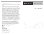
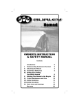
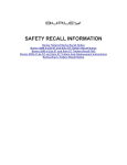
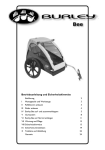
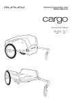
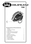
Installation Instructions
for ‘09 d’lite™, Encore and Solo™
(Euro) Child Trailers
Installation Instructions
for ‘09 d’lite™, Encore and Solo™
(Euro) Child Trailers
Contents:
Contents:
(1) Burley Owner’s Instruction and Safety Manual
(1) Hitch
(1) Clear light with batteries included
(1) Red light with batteries included
(2) Phillip Pan screws
(2) Brackets for lights
(1) Wheel guard assembly:
(2) wheel guards
(4) screws
(1) 5mm hex key wrench
(1) Burley Owner’s Instruction and Safety Manual
(1) Hitch
(1) Clear light with batteries included
(1) Red light with batteries included
(2) Phillip Pan screws
(2) Brackets for lights
(1) Wheel guard assembly:
(2) wheel guards
(4) screws
(1) 5mm hex key wrench
Tools Required:Phillips screwdriver
4mm hex wrench
10mm or open end wrench
Tools Required:Phillips screwdriver
4mm hex wrench
10mm or open end wrench
Note: Consult your Burley Owner’s
Note: Consult your Burley Owner’s
Figure 1
2. Using wrench, loosen and remove
lock nuts and screws from handle bar
receivers.
3. From trailer front, slide roll bar into upper
handle bar receivers, with curved front
extending above trailer body.
4. Match holes in roll bar and inner handle
bar receivers, re-install screws and
tighten lock nuts.
5. Replace outer handle bar receivers and
tighten knobs.
Screws
Handle bar
Knob
Inner Handle bar
Receiver
Roll Bar
FIGURE 1: Roll Bar Installation
Outer Handle bar
Receiver
1. If handle bar receivers are already
installed, loosen and remove handle bar
knobs and outer handle bar receivers.
Figure 1
2. Using wrench, loosen and remove
lock nuts and screws from handle bar
receivers.
3. From trailer front, slide roll bar into upper
handle bar receivers, with curved front
extending above trailer body.
4. Match holes in roll bar and inner handle
bar receivers, re-install screws and
tighten lock nuts.
5. Replace outer handle bar receivers and
tighten knobs.
ler
Roll Bar Installation
Tra
i
Tra
i
nt
of
Lock Nuts
Rear Assembly
Frame
Fro
1. If handle bar receivers are already
installed, loosen and remove handle bar
knobs and outer handle bar receivers.
ler
Roll Bar Installation
Instruction and Safety Manual for
wheel guard and hitch installation
instructions.
Lock Nuts
of
Instruction and Safety Manual for
wheel guard and hitch installation
instructions.
Rear Assembly
Frame
nt
®
Fro
®
Screws
Handle bar
Knob
Inner Handle bar
Receiver
Roll Bar
FIGURE 1: Roll Bar Installation
Outer Handle bar
Receiver
Light Installation
Note: Clear light is mounted facing
Light Installation
Front of Trailer
Red Light
forward, on side closest to traffic.
Red light is mounted facing rear, on
the side closest to traffic.
Red Light
Roll Bar
Note: Make sure on/off light switches
are accessible.
1. Remove clips and screws from back of
lights.
2. Using screws, fasten brackets and
lights together.
3. Mount clear light/bracket diagonally on
front of roll bar and red light/bracket on
rear of roll bar, both on side closest to
traffic. Photo 1
Front of Trailer
forward, on side closest to traffic.
Red light is mounted facing rear, on
the side closest to traffic.
Roll Bar
Note: Make sure on/off light switches
Note: Clear light is mounted facing
are accessible.
1. Remove clips and screws from back of
lights.
2. Using screws, fasten brackets and
lights together.
3. Mount clear light/bracket diagonally on
front of roll bar and red light/bracket on
rear of roll bar, both on side closest to
traffic. Photo 1
Clear Light
PHOTO 1: Light Installation
Locking Quick Release/
Wheel Installation
and Operation
Locking Quick Release/
Wheel Installation
and Operation
1. With quick release lever in “open”
position, insert wheel axle completely
into trailer axle receiver.
2. Close quick release lever, with lever
aimed towards rear of trailer. Photo 2
3. Verify that tires are inflated to pressure
marked on the tire side wall.
4. To remove wheel from trailer axle, push
locking button on side of quick release
lever and open lever.
Quick
Release
Lever
Rear of Trailer
Locking
Button
PHOTO 2: Wheel Installation
Note: The locking quick release lever
securely attaches the wheel to the
trailer. If you have difficulty removing
the wheel, release pressure on the
quick release by pushing the end
of lever in toward the trailer before
pushing the locking button.
WARNING
MAKE SURE WHEELS ARE HELD SECURELY,
WITH WHEEL SHAFT FULLY INSERTED INTO
AXLE RECEIVER. YOU SHOULD NOT BE ABLE
TO ROCK OR SHIFT WHEELS. IMPROPERLY
INSTALLED WHEELS CAN FALL OFF, CAUSING
AN ACCIDENT OR SERIOUS INJURY.
Clear Light
PHOTO 1: Light Installation
Quick
Release
Lever
Rear of Trailer
Locking
Button
PHOTO 2: Wheel Installation
Note: The locking quick release lever
securely attaches the wheel to the
trailer. If you have difficulty removing
the wheel, release pressure on the
quick release by pushing the end
of lever in toward the trailer before
pushing the locking button.
WARNING
MAKE SURE WHEELS ARE HELD SECURELY,
WITH WHEEL SHAFT FULLY INSERTED INTO
AXLE RECEIVER. YOU SHOULD NOT BE ABLE
TO ROCK OR SHIFT WHEELS. IMPROPERLY
INSTALLED WHEELS CAN FALL OFF, CAUSING
AN ACCIDENT OR SERIOUS INJURY.
BU R LEY DES IG N
BU R LEY DES IG N
Copyright © 2008 by Burley Design LLC. “Burley” is a registered trademark of Burley Design LLC : Rev 06/08 : 170056 Euro d’lite, Encore and Solo Installation Instructions r1
4020 Stewart Rd. Eugene, OR 97402 : PH 541.687.1644 800.423.8445 FAX 541.687.0436 : burley @ burley.com : www.burley.com
Copyright © 2008 by Burley Design LLC. “Burley” is a registered trademark of Burley Design LLC : Rev 06/08 : 170056 Euro d’lite, Encore and Solo Installation Instructions r1
4020 Stewart Rd. Eugene, OR 97402 : PH 541.687.1644 800.423.8445 FAX 541.687.0436 : burley @ burley.com : www.burley.com