1
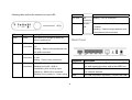
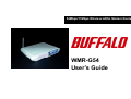
54Mbps/11Mbps Wireless ADSL Modem Router WMR-G54 User’s Guide 2 Table of Contents Introduction Introduction A Look at the Hardware Front Panel Back Panel Hardware Installation 3 3 4 4 5 Configure the Router for the first time Configuring IP Settings on Your Computer Configuring with Web Browser Device Info Quick Setup Configure WAN (DSL) Connectivity Configure Wireless Connectivity Declaration of Conformity 5 5 6 7 8 8 18 19 WMR-G54 Wireless ADSL Router allows you to share the single internet account. With built-in NAT, this Router allows up to 253 users on the Ethernet LAN simultaneously and up to 16 users on the 802.11g/b Wireless LAN simultaneously. WMR-G54 has the throughput speeds of up to 54Mbps and advanced Orthogonal Frequency Division Multiplexing (OFDM). In case of home usage, WMR-G54 acts as a gateway for Internet connection sharing. You can connect the Wireless ADSL Modem Router to your Internet connection directly, and use the wireless LAN to connect your computers to the Internet. A Look at the Hardware Front Panel The WMR-G54 Wireless ADSL Modem Router has nine Light Emitting Diodes (LEDs), or link lights, on its front panel. The 3 following table defines the behavior for each LED: transferred over the ADSL connection. PPP Link PPP Blinking – PPP is connected. Connection 11G Wireless LAN - Steady on – Wireless LAN access point is enabled. - Blinking – Data is being transferred over the Wireless LAN connection. LED Represents Activity / Status Power Power The Power LED will light up when the Back Panel device is powered on. USB USB Connection - Steady on – USB is connected to a host PC. - Blinking – Data is being transferred over the USB connection. 1, 2, 3, 4 LAN Steady on - when there is a connection to Connection the unit. DSL DSL Blinking – Data is being transferred. Connector Description - Off - ADSL link is not connected. ADSL Connect one end of the RJ-11 cable to the ADSL port and connect the other end to the ADSL line. LAN 1-4 Accepts a RJ-45 Ethernet cable for connecting up to 4 network devices. USB For USB connection (optional), connect the USB Connection - Blinking During Off - ADSL is handshaking and receiving signal. - Steady on - ADSL link is connected. - Blinking During steady on - Data is being 4 Reset cable to the USB port and connect the other end to the computer. Step 2. Connect the LAN port of the router to the Ethernet port of your computer with the Ethernet cable provided. Use an object, such as a stretched paper clip, to press the button for at least 3 seconds. LAN 1, 2, 3, 4 LED will light up for a short time and then be off. You can release the button now to reset the device to its factory-default settings. Step 3. Connect the 16V AC power adapter to the power socket of router, and plug the adapter into a mains power socket. Switch on the router. If the power is turned on, the PWR LED on the front panel will illuminate. On/Off Turn on the router by pressing up the power switch to the “On” position. Power Connect the power adapter to this Power port, and then plug the other end of the power cable into a power outlet. Configure the Router for the first time Hardware Installation Configuring IP Settings on Your Computer Thank you for purchasing the 54Mbps/11Mbps Wireless ADSL Modem Router WMR-G54. The following instructions will walk you through installation of the router. To configure WMR-G54 Wireless ADSL Modem Router for the first time, the configuration PC must have a static IP address. Use 192.168.1.x (x is any number between 2 and 254) and subnet mask 255.255.255.0. Specify gateway as 192.168.1.1 and enter DNS server IP. Step 1. Connect the ADSL port of the router into your ADSL wall socket with the provided cable. 5 For Windows 2000/Windows XP 1. then click Properties button. Right-click on My Network Places icon on the desktop and then click Properties in menu. 2. Double-click Local Area Connection icon click Properties button. 4. Check the radio button for Specify an IP address. In the IP address box, type the assigned IP address 192.168.1.x (x is any number between 2 and 254). 5. In the Subnet mask box, type the subnet mask 255.255.255.0. 6. In the default gateway box, type the default gateway IP address. For example, 192.168.1.1. 7. Click OK button in the TCP/IP Properties window to complete the PC configuration, and click Close or the OK button to close the Network window. and then Configuring with Web Browser Before you begin 3. Make sure that you get the setup information you need (for example, VPI, VCI, and type of encapsulation) from your Scroll down to highlight TCP/IP (your network card) and 6 Internet Service Provider (ISP). 3. After login, WMR-G54 Web UI screen will appear. The ADSL Modem Router can be configured with your web browser. The product provides a very easy and user-friendly interface for configuration. 1. Open your web browser. Enter http://192.168.1.1 in the web browser’s address field, and press the enter key. 2. A login window will appear. Enter admin in the User Name field and enter admin in the Password field. I. Device Info The Device Info page contains information of the software version of your device and some settings, such as IP Address and gateway. 7 II. Quick Setup 3. The Quick Setup will guide you through the steps necessary to configure your DSL Router. The ATM PVC Configuration page will appear. Enter the appropriate VPI and VCI values. Select appropriate Service Category. Click Next. III. Configure WAN (DSL) Connectivity PVC is identified by the VPI (Virtual Path Identifier) and VCI (Virtual Channel Identifier). Consult your ISP to get the numbers. 1. Click the Advanced Setup tab on the left frame. The valid range for the VPI number is from 0 to 255 (The default value is 0.). The valid range for the VCI number is from 32 to 2. Click the WAN tab on the left frame. A WAN Setup page will appear on the right frame. Click the Add button. 65535 (The default value is 35). There are five service categories provided: UBR Without PCR, 8 WMR-G54 ADSL Modem Router supports the following five network operating modes over an ATM PVC WAN interface: UBR With PCR, CBR, Non Realtime VBR, and Realtime VBR. PPP over ATM (PPPoA) PPP over Ethernet (PPPoE) MAC Encapsulated Routing (MER) IP over ATM (IPoA) Bridging The steps to configure PPP over ATM (PPPoA) are similar to PPPoE. PPP over Ethernet (PPPoE) 4. 5. 1. A Connection Type page will appear. There are several ways for the device to have a public IP address and then to access the Internet. You have to check with your ISP about which way is adopted. Check the radio button of your connection type. Select the PPP over Ethernet (PPPoE) radio button and scroll down to select the appropriate Encapsulation Mode. There are two encapsulation types available: LLC/SNAP-BRIDGING and VC/MUX. Then click the Next button. Scroll down to select the appropriate Encapsulation Type. 9 2. In the PPP Username and Password page, enter the user 3. name and password supplied by your ISP in PPP Username and PPP Password fields. Check the box Disconnect if no activity if you want to enable the function of automatic disconnection. It will auto-disconnect the ADSL Modem Router when there is no activity on the line for a period of time. PPP IP Extension is a special feature deployed by some service providers. Unless your ISP specifically requires this setup, do NOT select it. The PPP IP Extension supports the following conditions: 10 Allows only one PC on the LAN The public IP address assigned by the remote using the Service if you want to enable WAN Service. Click Next. PPP/IPCP protocol is actually not used on the WAN PPP interface. Instead, it is forwarded to the PC’s LAN interface through DHCP. Only one PC on the LAN can be connected to the remote since the DHCP server within the ADSL router has only a single IP address to assign to a LAN device. NAT and firewall are disabled when this option is selected. The ADSL Modem Router becomes the default gateway and DNS server to the PC through DHCP using the LAN interface IP address. 6. The ADSL router extends the IP subnet at the remote all WAN setting profiles. Click the Save button to save all the settings. service provider to the LAN PC. That is, the PC becomes a host belonging to the same IP subnet. The ADSL router bridges the IP packets between WAN and LAN ports, unless the packet is addressed to the router’s LAN IP address. 4. Click the Next button. 5. Check the box Enable IGMP Multicast if you want to enable IGMP multicast. Check the box Enable WAN The WAN Setup – Summary page displays a summary of 11 7. 8. The WAN Setup page will appear. Click the Save/Reboot button. The router will reboot automatically with the new settings in effect. 12 Close your Web UI window and wait for about 2 minutes before reopening your web browser. 2. IP over ATM (IPoA) 1. Select the IP over ATM (IPoA) radio button and scroll down to select the appropriate Encapsulation Mode. There are two encapsulation types available: LLC/Snap-Routing and DHCP is not supported over IpoA. Enter your WAN IP address, WAN Subnet Mask, gateway IP address and DNS server IP address provided by your ISP to configure the WAN IP settings. Then click the Next button. VC/MUX. Then click Next button. 13 provided by the ISP. The user may have many private addresses masked by the single address provided by the ISP. 4. If you want to enable the Firewall function, check the box Enable Firewall. If the Firewall is enabled, it will display a Firewall submenu on the left panel after reboot. Firewall will rejects any unsolicited data from the Internet to access the computer on your LAN. Basically, if you do not request data, the data will not be allowed by the firewall to pass. 5. 3. The Network Address Translation Settings page will appear. If you want to enable the NAT function, check the box If you want to enable IGMP Multicast, check the box Enable IGMP Multicast. If you want to disable it, uncheck the box. Enable NAT. If NAT is enabled, it will display a NAT submenu on the left panel after the unit reboots. 6. The default of WAN service is Enable. If you want to disable WAN service, uncheck the box Enable WAN Service. NAT occurs when multiple IP addresses on a private LAN are converted to one public address. This public address is sent out 7. Enter a desired name in the Service Name field. It is used to identify the service. 8. Click the Next button. to the Internet. NAT increases security because the IP address for a PC connected to the private LAN is never transmitted to the Internet. NAT also allows xDSL/cable routers to be used with low-cost Internet accounts, where only one TCP/IP address is 14 8. 9. The WAN Setup – Summary page displays a summary of Bridging all WAN setting profiles. Click the Save button to save all the settings. 1. The WAN Setup page will appear. Click the Save/Reboot button. The router will reboot automatically with the new settings in effect. Select the Bridging radio button and scroll down to select the appropriate Encapsulation Mode. There are two encapsulation types available: LLC/Snap-Bridging and VC/MUX. Then click the Next button. 15 The LAN IP in bridge operating mode is needed for local users to 2. Check the box Enable Bridge Service. Enter a desired name in the Service Name field. It is used to identify the service. Then click the Next button. manage the ADSL Modem Router. And no IP address is needed for the WAN in bridge mode. 3. The WAN Setup – Summary page displays a summary of all WAN setting profiles. Click the Save button to save all the settings. 16 4. 5. The WAN Setup page will appear. Click the Save/Reboot button. The router will reboot automatically with the new settings in effect. 17 Close your Web UI window and wait for about 2 minutes before reopening your web browser. 3. IV. Configure Wireless Connectivity 1. Click the Wireless tab on the left frame. A Wireless - Basic page will appear on the right frame. Check the box Enable Wireless. The default value is WMR-G54. All workstations and access points must use the same SSID to be able to communicate with one another. The SSID is a 32-character field, and the value is case sensitive. 4. 2. Enter a desired name in SSID field. This SSID is a network name that identifies the wireless devices in the network. Check the box Hide Access Point and then your WMR-G54 will not respond when a ping is sent by any user on the Internet. This feature is helpful if you do not want to let other Internet users to check the status of your WMR-G54. However, the station will not be able to find your WMR-G54. 18 Click the Apply button. Europe – EU Declaration of Conformity This device complies with the essential requirements of the R&TTE Directive 1999/5/EC. The following test methods have been applied in order to prove presumption of compliance with the R&TTE Directive 1999/5/EC: This device is a 2.4 GHz wireless LAN transceiver, intended for home and office use in all EU and EFTA member states, except in France, Belgium and Italy where restrictive use applies. EN 60950 (2000-06) In Italy the end-user should apply for a license at the national spectrum authorities in order to obtain an authorization to use Safety of Information Technology Equipment the device for setting up outdoor radio links. - EN 300 328-1/-2 (2001-12) Technical requirements for spread-spectrum radio equipment In Belgium there is a restriction in outdoor use. The frequency range in which outdoor operation in Belgium is permitted is 2460 – 2483.5 MHz. - EN 301 489-1 (2000-08) EN 301 489-17 (2000-08) EMC requirements for spread-spectrum radio equipment This device may not be used for setting up outdoor radio links in France. For more information see http://www.anfr.fr/ and/or http://www.art-telecom.fr - 19 Buffalo Technology Europe Wireless products helpdesk Buffalo Technology UK 176, Buckingham Avenue Slough, Berkshire, SL1 4RD United Kingdom +44 8712 501260* (UK & Ireland) +44 1753 555050* (Rest of Europe) [email protected] Tel. +44 (0) 1753 555000 Fax. +44 (0) 1753 535420 Buffalo Technology Ireland Free Zone East Shannon Co. Clare Ireland Tel. +353 61 708090 Fax. +353 61 360140 * 8.5p/13c per minute + local charge www.buffalo-technology.com www.buffalo-technology.de P/N 9000-0024 20