1
Service Manual for:
CA
Millennium
HZg^Zh
Public Use Wheelchair Lifts
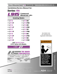
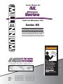
Series 05
DOT — Public Use Lift
“DOT — Public Use Lift” verifies that this platform lift meets the
“public use lift” requirements of FMVSS No. 403. This lift may be
installed on all vehicles appropriate for the size and weight of the
lift, but must be installed on buses, school buses, and multipurpose passenger vehicles other than motor homes with a gross
vehicle weight rating (GVWR) that exceeds 4,536 kg (10,000 lb).
WARNING
Man
"Providing Access to the World"
®
®
Patent #5,261,779
Patent #6,599,079
33126
Patent #6,065,924
Patent #6,692,217
August
Patent #6,238,169
Patent #6,739,824
2006
Patent #6,464,447
Patents Pending
l
Read manual
before installing
or servicing lift.
Failure to do so
may result in
serious bodily
injury and/or
property damage.
Braun NL Series
International Corporate Hdqrs: P.O. Box 310 Winamac, IN 46996 USA
1-800-THE LIFT ®
(574) 946-6153
FAX: (574) 946-4670
ua
Congratulations
We at The Braun Corporation wish to express our fullest appreciation
on your new purchase. With you in mind, our skilled craftsmen have designed and
assembled the finest lift available.
This manual provides service-related material. Refer to the FMVSS No. 403
Quick Reference Installation Sheet for installation instructions, operating instructions
and maintenance procedures.
Braun Millennium Series™ lifts are built for dependability and will provide years
of pleasure and independence as long as the lift is installed and serviced as specified
by a Braun certified technician, and the lift is operated by an instructed person.
Sincerely,
THE BRAUN CORPORATION
Ralph W. Braun
Chief Executive Officer
Warranty and Registration Instructions
Immediately upon receiving the lift, examine the
unit for any damage. Notify the carrier at once
with any claims.
Series No.
Pump Code
Model No.
Serial No.
Cylinder Code
OWNER'S WARRANTY REGISTRATION
NL917IB-05-00025-56-14CG
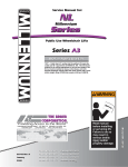
Two warranty/registration cards (shown right) are
located in the lift-mounted manual storage pouch.
The sales representative must process one of the
cards. The consumer must fill out the other card
and mail it to The Braun Corporation. The warranty is provided on the back cover of this manual.
The warranty cards must be processed to
activate the warranty.
PURCHASED FROM
OWNER
DATE INSTALLED
NAME
ADDRESS
CITY
TELEPHONE
STATE
ZIP
TO VALIDATE WARRANTY
REGISTRATION CARDS MUST BE RETURNED TO THE BRAUN CORPORATION.
Sample Warranty/Registration Card
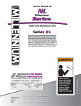
Two Braun Serial No./Series No. identification tags (shown below) are posted on the lift.
One I.D. tag is posted on the opposite pump side vertical arm. A second I.D. tag is located
on the opposite pump side tower. Both I.D. tags provide the product identification information provided on the warranty/registration card. Record the information in the space
provided (or document on a copy). This information must be provided when filing
a warranty claim or ordering parts.
The Braun Corporation
1-800-THE LIFT™
BRAUNLIFT.COM™
Model No.
DOT Public Use Lift MODEL#
NL917IB
Max. Lifting Capacity - 800 lbs.
Series No.
SERIAL NUMBER
05-00025
PUMP CODE
CYLINDER
56
Serial No.
14CG
MFG DATE
06/19/06
Pump Code
e5*72/245*95/54*0110*00
PATENT
PENDING- 5,261,779-6,065,924-6,238,169-6,46
4,447-6,599,079-6,692,217-6,739,824
6DPSOH6HULDO1R6HULHV1R,GHQWLÀFDWLRQ7DJ
Cylinder Code
Date of Manufacture
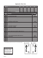
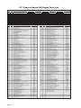
Contents
Troubleshooting and Maintenance
Lift Terminology ............................................................ 2
Switch and Sensor Locations ...................................... 3
Certification Checklist Diagnostic Procedures .......... 4
Platform Fold Pressure Adjustment............................. 5
Outer Barrier Fold Pressure Adjustment..................... 5
Platform Angle Adjustment ....................................... 6-7 Platform Stop Blocks .................................................... 7 Platform Floor Level Adjustment ................................. 8
Bridging Microswitch Adjustment ............................... 9
LCD Lift Codes ....................................................... 10-11
Lubrication Diagram ................................................... 12
Maintenance and Lubrication Schedule . ............. 13-15
Notes............................................................................. 16
Lift Electrical Schematic ............................................. 17
Lift Wiring Diagram ..................................................... 18
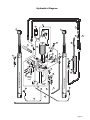
Hydraulics
Hydraulic Schematic ................................................... 19
Hydraulics Parts List . ................................................. 20
Hydraulics Diagram . ................................................... 21
Repair Parts
Pump Module
Pump Module Parts List ........................................ 22
Pump Module Diagram .......................................... 23
Lift Exploded Views
42" Floor-to-Ground Lift Models
(NL915IB, NL915FIB, NL918IB, and NL918FIB)
Repair Parts List .................................................... 24
Exploded View......................................................... 25
48" Floor-to-Ground Lift Models
(NL916IB, NL916FIB, NL917IB, NL917FIB,
NL919IB and NL919FIB)
Exploded View ........................................................ 26
Repair Parts List..................................................... 27
Notes........................................................................ 28
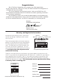
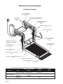
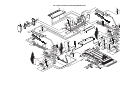
Page Lift Terminology
Hand-Held
Pendant
Control
32819
UP
FOLD
32820
Top Parallel Arms (2)
Visual
Threshold
Warning
N
DOW
UNFO
Lift-Tite™ Latches (2)
Towers (2)
Main Cylinders (2)
LD
®
Audible
Threshold
Warning
Unfold Assist Compression Springs (2)
Adjustable Quiet-Ride Stow Blocks (2)
Platform Lights
Opposite Pump Side Vertical Arm
Vertical Arm Covers (4)
Pump
Module
(Rear)
Threshold
Warning
Plate
Handrails (2)
Base
Plate
Inner Roll Stop
Bottom Parallel
Arms (2)
Rotating Pivot
Slide Arms (2)
Platform Pivot Arms (2)
Platform
Pump Side Vertical Arm
Outer Barrier Cylinder
(not visible -underside of platform)
Platform Side Plates (2)
Outer Barrier
(Automatic Outboard Roll Stop)
Outer Barrier Latch
Inboard
Left
Inboard
(driver's side)
Right
Outboard
Front
(of vehicle)
NL917-05-003.ai
Rear
(of vehicle)
Page Outboard
(passenger's side)
“Arrows/30°-30°”6-13-90
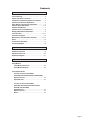
Switch and Sensor Locations
Pressure Switch
31199
32819
UP
Threshold Strip Switch
31221A (Qty. 2)
*IB Occupancy
Microswitch Assy.
32642A
DOWN
LD
UNFO
FOLD
32820
®
*Bridging
Microswitch
31010FA
*Stow
*Rotary
Position
Sensor
31094A
Microswitch
23184 (Qty. 2)
Outer Barrier Latched
Magnet
31664
Outer Barrier Latched
Magnetic Sensor
32645NA60
Outer Barrier Raised
Magnetic Sensor
32645NA60
Inboard
Left
Right
Outboard
Outer Barrier Raised
Magnet
31664
*Note: Mirror image for
right (front) pump lifts.
NL917-05-033.ai
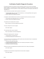
Page Certification Checklist Diagnostic Procedures
The following operations and conditions must be functionally verified in order for the lift to be FMVSS
403/404 compliant. If an operation does not function as described or a condition is not met, follow the referenced procedures to correct the problem or contact a Braun Corporation Product Support representative at
1-800-THE LIFT®.
• Vehicle movement is prevented unless the platform is fully stowed.
1. Verify lift stowed signal - pin 7 on the pump module has a +12 volt signal OR pin 9 has a ground
signal (depends on interlock used).
2. Refer to the interlock installation instructions.
• Lift operation shall be inhibited unless the vehicle is stopped and vehicle movement is prevented.
1. Verify vehicle secure signal (pin 6) has a +12 volt signal.
2. Refer to the interlock installation instructions.
• The platform will not fold/stow when occupied.
- Refer to Platform Fold Pressure Adjustment procedures.
• The inner rollstop will not raise if occupied.
- Call Product Support
• The outer barrier will not raise if occupied.
- Refer to Outer Barrier Fold Pressure Adjustment
• Verify platform lighting when lift is deployed.
1. Replace bulb(s) in the light housing.
2. Check fuse (5 amp fuse on circuit board; F13)
• An audio warning (and visual warning for public lifts) will activate if the threshold area is occupied when
the platform is a least 1" below floor level.
1.
2.
3.
4.
Remove the threshold warning plate
Verify the threshold strip switch connectors are connected (see illustration on Page 3)
Replace the threshold strip switch
Reinstall the threshold warning plate
• Platform movement is prohibited beyond the position where the inner rollstop is fully deployed.
- Call Product Support.
• Lift platform movement shall be interrupted unless the outer barrier is deployed.
- Call Product Support.
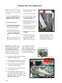
Page Platform Fold Pressure Adjustment
1. Position the platform at the floor level loading
position.
2. Loosen the hex nut on the adjustment screw (do
not remove hex nut).
3. Turn the adjustment screw counter clockwise
until the platform does not fold when the Fold
button is pressed.
4. Turn the adjustment screw clockwise in 1/4 turn
increments and press the Fold button until the
platform folds completely (Note: return the platform to floor level position after each attempt to
fold the platform).
5. Turn the adjustment screw an additional 1/8 turn
after the platform folds successfully.
6. Tighten the hex nut without moving the adjustment screw.
7. Verify the platform will not stow while occupied.
Platform Fold
Adjustment
Allen Screw
Note: Secure adjustment
screw and tighten hex
nut following adjustment.
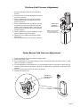
Outer Barrier Fold Pressure Adjustment
1. Lower the platform to the ground level loading position.
2. Remove the pump cover.
3. Turn the adjustment screw (shown below) counter clockwise until the outer barrier does not raise
when the Up button is pressed.
4. Turn the adjustment screw clockwise in 1/4 turn increments until the outer barrier raises and fully
locks in position when the Up button is pressed. DO NOT turn the adjustment screw beyond this
position.
5. Verify the outer barrier will not raise when occuppied.
6. Reattach the pump cover.
Outer Barrier
Fold Adjustment
Allen Screw
32819
UP
DOWN
LD
UNFO
FOLD
32820
®
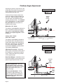
Page Platform Angle Adjustment
Adjusting the platform angle based on the
relationship of the platform at ground level
directly affects the angle of the platform
ZKHQSRVLWLRQHGDWÁRRUOHYHO
Millennium “NL” Series
Figure C
Unfold the lift and visually examine the
angle of the platform when positioned at
ÁRRUOHYHO/RZHUWKHSODWIRUPIXOO\DQG
note the angle of the platform when it
reaches ground level also. The outboard
HQGRIWKHSODWIRUP (toe) must contact
the ground ÀUVW when the platform is
lowered (all lift models).
Angle $
equals
Angle%.
Millennium “NL” Series:
The platform angle should be adjusted so
there is a balance between the angle at
both positions (equal amount of angle).
$QJOH$ should HTXDODQJOH%as shown
LQ)LJXUH&
Century “NCL” Series:
9LVWD´19/µ6HULHV
The platform angle must be adjusted so
the outboard end of the platform (toe) is
angled down slightly when positioned at
ÁRRUOHYHO6HH)LJXUH'7KHRXWERDUG
end of the platform must contact the
JURXQGÀUVWWRensure the spring-loaded
outer barrier unfolds fully.
$
Wedges
%
Approximately
1” Clearance
Inboard
Outboard
Century “NCL” Series
9LVWD´19/µ6HULHV
$GMXVWPHQW3URFHGXUHV Adjustment
Allen screws are provided on each side of
the lift platform for adjusting the platform
DQJOH'HWDLOVDQGSKRWRVDUHSURYLGHG
on the opposite page.
Figure D
%DVH3ODWH:HGJHV Installations where
base plate wedges are used require more
platform angle adjustment than normal.
Toe must
angle
down
slightly.
3ODWIRUP6WRS%ORFNV When adjusting platform angle, ensure both
VWRSEORFNVDUHPDNLQJIXOOFRQWDFW
ZLWKWKHYHUWLFDODUPV (details on
opposite page).
)ORRU/HYHO$GMXVWPHQW)ROORZing platform angle adjustment, set
ÁRRUOHYHOSRVLWLRQLQJDVGHWDLOHGLQ
3ODWIRUP)ORRU/HYHO$GMXVWPHQW
(details on page 8).
Page 6
Barrier
must
unfold
fully.
Wedges
Inboard
Outboard
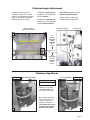
Platform Angle Adjustment
Adjustment Allen screws are
provided on each side of the lift
platform for adjusting the platform
angle. Adjust platform angle as
VSHFLÀHGRQSUHYLRXVSDJH
Note: %RWK adjustment screws
PXVWEHDGMXVWHGHTXDOO\.
To raise the outboard end
of platform - turn adjustment
screw FORFNZLVH.
Apply Loctite® to adjustment
screws following adjustment.
To lower the outboard end
of platform - turn adjustment
screw FRXQWHUFORFNZLVH.
Platform Angle
Adjustment Screws
Adjustment Screw
Allen Head
%
$
Turn
counterFORFNZLVH
to lower
outboard
end of
platform
Turn
FORFNZLVH
to raise
outboard
end of
platform
Platform Stop Blocks
Right
0XVWPDNHIXOOFRQWDFW.
Gap QRWSHUPLWWHG.
Wrong
6WRS%ORFN*XLGHOLQH
$OO/LIW0RGHOV
Vertical Stop
Arm Block
C
%RWK stop blocks must
PDNHIXOOFRQWDFW with
the edge of vertical arms.
Vertical
Arm
When adjusting platform
DQJOHVHWWLQJÁRRUOHYHO
position or adjusting
bridging microswitch ensure both VWRSEORFNV
DUHPDNLQJIXOOFRQWDFW
ZLWKWKHYHUWLFDODUPV.
Stop
Block
'
Page 7
Platform Floor Level Adjustment
%HIRUHVHWWLQJÁRRUOHYHOSRVLWLRQ
tion if unable to stop platform
when powering lift.
• Adjust platform angle as detailed
on page 6.
2. Turn Lift Power switch Off.
• Ensure both VWRSEORFNVDUH
PDNLQJIXOOFRQWDFWZLWKYHUWLcal arms (details on page 7).
3UHVV)ORRU3RVLWLRQ6HWEXWton (located between pump
housing and lift tower).
)ORRU/HYHO$GMXVWPHQW
:KLOHSUHVVLQJWKH)ORRU3Rsition Set button, turn the Lift
Power switch On.
1. Position platform at desired
ÁRRUOHYHOSRVLWLRQSDVVHQJHU
loading/unloading height).
Position platform such that:
a. the inner roll stop is laying
ÁDWRQWKHWKUHVKROGSODWH
b. platforrm has not begun to
fold
Note: Use hand pump to position platform at proper posi-
'LDJQRVWLFV'LDJQRVWLFFRGHV
have been established in event
WKHOLIWSODWIRUPÁRRUSRVLWLRQ
does not set (the lift does not
sound three “beeps” - see Step
5 above). The control board
located inside the pump hous-
E
&RQWLQXHSUHVVLQJWKH)ORRU
Position Set button until the
lift sounds three “beeps.”
5HOHDVHWKH)ORRU3RVLWLRQ
Set button.
7. Cycle lift to verify that platIRUPVWRSVDWWKHVHWÁRRU
level position. Note: If
platform does not stop at
LQJLVHTXLSSHGZLWKDQ/&'
screen. Remove the pump
FRYHUWRDFFHVVWKH/&'
screen. The following diagnosWLFFRGHVZLOOKHOSUHVROYHÁRRU
position setting problems:
91 – The platform position is out of a predetermined acceptable range
)ORRU/HYHO6HW%XWWRQ
the intended position - repeat
adjustment procedures. If repeating procedures fails - refer
WR'LDJQRVWLFVVHFWLRQEHORZ
Century/Vista Jumper
/&'6FUHHQ
92 – The Bridging Microswitch is not activated (adjust switch or lower the platform)
93 – The Inner Roll Stop Occupied switch is
not activated (adjust switch)
94 – The Outer Barrier Up switch is not activated (adjust switch)
95 – The Outer Barrier Latched sensor is
not activated (Century and Vista: Verify
jumper is installed on the outboard
barrier latch switch – see photo at right;
Millennium: Check latch)
Page 8
)
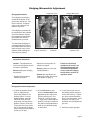
Bridging Microswitch Adjustment
Adjustment Screw
%ULGJLQJ0LFURVZLWFK
Bridging Microswitch
*
H
The bridging microswitch is
located at the bottom of the
right (front) vertical arm. See
Photos A and B. An adjustment screw is built into the
platform stop block.
The bridging microswitch will
be deactivated if the outboard
end of the platform contacts
the unloading surface before
the inboard end while the
'2:1VZLWFKLVSUHVVHG
The deactivated bridging microswitch interrupts power to
WKH'2:1VZLWFKFLUFXLWDQG
stops the down travel of the
platform (while allowing the
outer barrier to deploy).
Inboard Vertical
Edge of Vertical Arm
Platform
Stop Block
Switch
Activation Lever
$GMXVWPHQW*XLGHOLQHV
Caution: This adjustment is
factory set and typically should
not require adjustment.
%HIRUH adjusting the bridging
microswitch:
• Adjust platform angle as
detailed on page 6.
$GMXVWÁRRUOHYHOSRVLWLRQDV
detailed on page 8.
• Ensure platform is in the fully
unfolded position.
• Ensure both stop blocks are
making full contact with vertical
arms (details on page 7).
)DLOXUHWRIROORZWKHVH
guidelines will result in an
RYHUWLJKWDGMXVWPHQWWKDW
ZLOOEHQGWKHDGMXVWPHQW
VFUHZEUHDNWKHEULGJLQJ
VZLWFKDQGRUUHVXOWLQOLIW
RSHUDWLRQIDLOXUH.
%ULGJLQJ0LFURVZLWFK$GMXVWPHQW
3RVLWLRQWKHSODWIRUPDWÁRRU
level (or slightly below).
Ensure the platform is not
SDUWLDOO\IROGHG)URPWKH
stowed position, press the
81)2/'VZLWFKXQWLOWKH
pump stops running and the
platform comes to a full stop.
)URPEHORZÁRRUOHYHOSUHVV
the UP switch until the pump
stops running and the platform
comes to a full stop.
2. Check both platform stop
blocks to ensure there is no
JDS between the stop blocks
and the vertical arms. See
3KRWRV%&DQG'RQSDJH
7. A gap may indicate that the
platform is not fully unfolded or
the platform angle adjustment
bolts are not adjusted equally
on both sides.
3. Loosen the two jam nuts on
the bridging switch activation
screw (see Photo G). Tighten
the screw until the activation
lever is fully depressed. Verify
that there is no play in the
activation lever and tighten the
jam nuts.
4. Test lift for proper operation.
Page 9
LCD Lift Codes
7REHWWHUXQGHUVWDQGWKH%UDXQ/&'7URXEOHVKRRWLQJGLVSOD\\RXPXVWÀUVWXQGHUVWDQGWKHQXPEHUVWKDW
DSSHDURQWKHVFUHHQ7KHUHDUH)ODVKLQJ&RGHV6ROLG(UURU&RGHVDQG6ROLG1RUPDO2SHUDWLRQDO&RGHV
)ODVKLQJ&RGHV About 10 seconds after an operation has stopped there are a set of scrolling
ÁDVKLQJQXPEHUVWKDWLQGLFDWHZKHQHYHUDSDUWLFXODUVHQVRURUVZLWFKKDVEHHQDFWLYDWHG7KHVHQXPEHUV
will start at number 65 and scroll up to number 89, then start the sequence over. Remember they are not
HUURUFRGHV.HHSLQPLQGWKDWWKHOLIWZLOOGLVSOD\FRGHVIRUGLIIHUHQWSRVLWLRQVDQGFHUWDLQÁDVKLQJFRGHV
must be present for that position, you will not always get an error code.
6ROLG(UURU&RGHV These are the numbers that will come on the screen when the audible and
visual alarm goes off, and will direct you to where the problem exists. These numbers will only stay on the
VFUHHQIRUDERXWVHFRQGVDQGWKHQWKHÁDVKLQJFRGHVZLOOVFUROOLQGLFDWLQJZKDWVHQVRUVDUHDFWLYH7KLV
sequence of codes will keep repeating. It is important to be looking at the screen when trying to get the lift
to fail.
6ROLG1RUPDO2SHUDWLRQDO&RGHV There are also solid numbers that will appear while and after the lift is
moving that indicate the lift operation and platform position.
7URXEOHVKRRWLQJ3URFHGXUHV
1. While ORRNLQJDWWKH/&'VFUHHQRSHUDWHWKHOLIWXQWLOWKHIDLOXUHRFFXUV5HDGWKHQXPEHUWKDWFRPHV
RQWKHGLVSOD\WKHPRPHQWWKHDODUPJRHVRIIDQGWKHOLJKWVWDUWVWRÁDVK7KLVFRGHZLOORQO\VWD\RQWKH
screen for 10 seconds.
2. Look up the number on the correct error code sheet and determine what part on the lift is causing the
failure. Go to the part on the lift that is suspected of causing the failure and look for anything obvious like
magnets missing, broken wires etc. If nothing is found, the next step is to determine if that sensor is sending a signal to the board.
3. Bring the platform to the level that the sensor should be activated using the backup pump if needed. At
WKLVSRLQWORRNXSWKHÁDVKLQJFRGHWKDWFRUUHVSRQGVWRWKDWVHQVRULQWKHHUURUFRGHVKHHWORRNDWWKH/&'
VFUHHQDQGZDLWIRUWKHÁDVKLQJVFUROOLQJQXPEHUVWRDSSHDU,IWKHQXPEHULVQRWLQFOXGHGLQWKHVFUROOLQJ
numbers, you know that sensor is the problem. You should then check the harness or try another magnet
with the south side of the magnet facing the sensor and see if the number will come up on the display.
4. If the problem is still not found or the harness is suspected, the voltages should to be checked to and
IURPWKHVHQVRUWRÀQGWKHH[DFWORFDWLRQRIWKHSUREOHP)LUVWGHWHUPLQHWKHZLUHFRORUVIRUWKLVVHQVRUDW
the board and understand the 3 voltage readings needed to operate the sensor, the 12V power, 8V power,
DQGWKH9LQSXWVLJQDOWRWKH3&ERDUGZKHQDFWLYDWHGE\DPDJQHW)LUVWFKHFNIRUD9LQSXWVLJQDO
coming from the sensor to the wire going into the PC board, if there is 11V on this wire, the sensor is not
being activated by the magnet. Next check the 12V and 8V wires at the PC board plug leading to the senVRU2QFHYHULÀHGDWWKHSOXJRQWKH3&ERDUGWKHYROWDJHVVKRXOGWKHQEHFKHFNHGDWWKHQH[WSOXJGRZQ
on the harness going to the sensor until the location of the problem is found.
$Q\WLPH\RXVHHWKHFRGHIRUWKDWVSHFLÀFVZLWFK\RXZLOOKDYHYROWVRQWKDWFRORUHGZLUHRQWKHRU
pin connector from that switch. IE: Outboard Barrier is closed “72” will appear on the screen and also 8V
will be present on the signal wire from that switch, if no code is present the voltage will be 11V.
Page 10
LCD Lift Codes
Listed below are codes that the lift controller outputs
during lift operation. The codes will be displayed
RQDQ/&'VFUHHQORFDWHGRQWKHOLIWFRQWUROERDUG
inside the pump module. See the Manual Operating
Instructions in the operator's manual for pump cover
removal instructions.
1RQ)ODVKLQJ1XPEHUV
01 – Platform stowed
02 – Platform unfolding
03 – Platform unfolding paused
²3ODWIRUPDWÁRRUOHYHO
05 – Platform beginning to lower
06 – Platform lowering (threshold cannot be occupied from this point down)
07 – Outer barrier moving to horizontal position
08 – Platform at ground level
09 – Outer barrier moving to vertical position
10 – Platform raising
²3ODWIRUPUDLVLQJSDXVHGDWÁRRU
12 – Platform folding (limited pressure)
13 – Platform folding (full pressure)
14 – Timed fold (cinching lift tite) or (anti-rattle state)
15 – Platform folding stopped
16 – Paused fold
17 – Platform between ground and 3” above ground
18 – Platform above 3”
19 – Outer barrier moving to horizontal postion
23 Outer barrier going back down after occupant
detected
²,OOHJDOIXQFWLRQQRWGHÀQHG
29 – Interlock fault not recognized (or has been
cleared but a motion button is still pressed)
30 – Platform location unknown
31 – Platform location transition state; attempting to
locate position
35 – Two or more motion buttons are being pressed
36 – The retention belt cannot be buckled while trying to fold or unfold
37 – Motion button being pressed is not a valid motion
50 – Outer barrier is not up above inboard barrier
locked position
51 – Threshold is occupied when platform is 1” or
PRUHEHORZÁRRUOHYHO
52 – Inner rollstop is not up and locked below inner
rollstop locked position
53 – Inner rollstop occupied sensor is not activated
EHWZHHQÁRRUDQGLQQHUUROOVWRSXSSRVLWLRQ
54 – Outer barrier is occupied before it is up
55 – Outer barrier is not latched when above the inner rollstop locked position (Millennium only)
56 – Outer barrier is not up and latched and bridge
switch did not deactivate
57 – Outer barrier is not up and latched and
ground detect switch did not deactivate (Century
and Vista only)
58 – Outer barrier is not up and latched and the platform is 3” above the ground
59 – Outer barrier is not up after pausing platform
travel
60 – The kickout gas springs are worn, replace before
using
75 – Low voltage detected; must turn off power switch
WRUHVHW/&'
77 – Vehicle secure interlock has not been activated
90 – Position will be set if you keep holding the button
until it beeps
91 – Position is out of a predetermined acceptable
UDQJHRIÁRRUSRVLWLRQ
92 – Bridge switch is not made, needs adjusting
93 – Inner rollstop occupied switch is not made,
position needs to be moved or switch should be
adjusted
²2XWHUEDUULHULVQRWPDGHÀ[DQGWU\DJDLQ
95 – Outer barrier latch is not made (check for jumper
on Century and Vista lifts, check latch on Millennium lifts)
99 – Controller program is not valid; replace controller
)ODVKLQJ1XPEHUV
)ODVKLQJ²8QIROGEXWWRQLVSUHVVHG
)ODVKLQJ²)ROGEXWWRQLVSUHVVHG
)ODVKLQJ²'RZQEXWWRQLVSUHVVHG
)ODVKLQJ²8SEXWWRQLVSUHVVHG
)ODVKLQJ²%ULGJHVZLWFKLVDFWLYDWHG
)ODVKLQJ²2XWHUEDUULHUODWFKVZLWFKLVDFWLYDWHG
)ODVKLQJ²*URXQGGHWHFWVZLWFKLVDFWLYDWHG
)ODVKLQJ²2XWHUEDUULHUXSVZLWFKLVDFWLYDWHG
)ODVKLQJ²,QQHUUROOVWRSXSVZLWFKLVDFWLYDWHG
)ODVKLQJ²,QQHUUROOVWRSRFFXSLHGVZLWFKLVDFWLvated
)ODVKLQJ²2XWERDUGEDUULHURFFXSLHGVZLWFKLV
activated
)ODVKLQJ²7KUHVKROGWDSHVZLWFK´$µLVDFWLYDWHG
)ODVKLQJ²7KUHVKROGWDSHVZLWFK´%µLVDFWLYDWHG
)ODVKLQJ²3RVLWLRQVHWEXWWRQLVSUHVVHG
Page 11
Maintenance and Lubrication
Lubrication Diagram
Lift-Tite Latches
(Tower Pivot Points - 2)
LO
32819
UP
N
DOW
UNFO
FOLD
32820
Parallel Arm
Pivot Pins (8)
LO
LD
®
Lift-Tite Latch Dampening Spring
(2 springs - 4 Points) LO
Rotating Pivot Slide
Arm UHMW Slide (1)
DE
Parallel Arm Pivot Pins (8)
LO
Handrail Pivot Pins (2)
LO
Inner Roll Stop (IB)
Pivot Points
LO
Rotating Pivot Slide Arm
UHMW Bearings (2) DE
Outer Barrier Hinge
Pivot Points (2)
LO
Rotating Pivot
Slide Arm Pivot Pins
LO
Platform Fold Axles (2)
LO
Platform Pivot Pin (2 Points)
LO
Lift-Tite Latch Roller Assemblies (2)
LO
Outer Barrier Latch LO
Outer Barrier Latch Lever
LO
See the Maintenance/Lubrication Schedule for recommended applications per number of cycles.
Lubricant
LO - Light Oil
DE - Door-Ease
LG - Light Grease
Page 12
Type
Specified (recommended)
Lubricant
Available
Amount
ight Penetrating Oil
L
LPS2, General Purpose11 oz.
(30 weight or equivalent)
Penetrating Oil
Aerosol Can
Stainless Stick
Door-Ease1.68 oz.
Style (tube)
Stick (tube)
Light Grease
Lubriplate14 oz.
(Multipurpose)
Can
NL917-05-003.ai
Braun
Part No.
15807
15806
15805
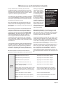
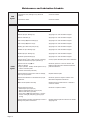
Maintenance and Lubrication Schedule
Proper maintenance is necessary to ensure safe,
troublefree operation. Inspecting the lift for any wear,
damage or other abnormal conditions should be a part
of all transit agencies’s daily service program. Simple
inspections can detect potential problems.
The maintenance and lubrication procedures specified
in this schedule must be performed by a Braun authorized service representative at the scheduled intervals
according to the number of cycles.
Braun dual parallel arm lifts are equipped with hardened pins and self-lubricating bushings to decrease
wear, provide smooth operation and extend the service
life of the lift.
When servicing the lift at the recommended intervals,
inspection and lubrication procedures specified in
the previous sections should be repeated. Clean the
components and the surrounding area before applying lubricants. LPS2 General Purpose Penetrating
Oil is recommended where Light Oil is called out.
Use of improper lubricants can attract dirt or other
contaminants which could result in wear or damage
to the components. Platform components exposed to
contaminants when lowered to the ground may require
extra attention.
Lift components requiring grease are lubricated during
assembly procedures. When these components are
replaced, grease must be applied during installation
procedures. Specified lubricants are available from
The Braun Corporation (part numbers provided above).
All listed inspection, lubrication and maintenance
procedures should be repeated at “750 cycle” intervals
750
Cycles
following the scheduled
“4500 Cycles” maintenance. These intervals
are a general guideline
for scheduling maintenance procedures and
will vary according to
lift use and conditions.
Lifts exposed to severe
conditions (weather, environment, contamination,
heavy usage, etc.) may
require inspection and
maintenance procedures
to be performed more
often than specified.
WARNING
Maintenance and
lubrication procedures
must be performed as
specified by an
authorized service
technician. Failure to
do so may result in
serious bodily injury
and/or property
damage.
Maintenance Indicator: The Lift Ready green LED
mounted on top of the pump cover will begin to blink
after every 750 cycles. The blinking LED will not affect
the functions of the lift, but is a reminder to complete
necessary maintenance and lubrication.
Once the lift has been serviced, fully stow the lift. Once
stowed, press the UP button on the hand pendant and
the Floor Level Set button on the back side of the pump
cover until the Lift Ready green LED stops blinking.
Discontinue lift use immediately if maintenance and
lubrication procedures are not properly performed, or if
there is any sign of wear, damage or improper operation. Contact your sales representative or call The
Braun Corporation at 1-800-THE LIFT®. One of our
national Product Support representatives will direct you
to an authorized service technician who will inspect your
lift.
Outer barrier hinge pivot points (2)
Apply Light Oil - See Lubrication Diagram
Outer barrier latch (pivot/slide points)
Apply Light Oil - See Lubrication Diagram
Outer barrier latch lever pivot points
Lift-Tite™ latches (tower pivot points - 2)
Apply Light Oil - See Lubrication Diagram
Apply Light Oil - See Lubrication Diagram
Lift-Tite™ latch gas (dampening) spring pivot
points (2 springs - 4 points)
Apply Light Oil - See Lubrication Diagram
Inspect Lift-Tite™ latches and gas springs for wear
or damage (bent, deformed or misaligned), positive securement (external snap rings) and proper
operation Resecure, replace defective parts or otherwise
correct as needed. Note: Apply Light Grease to
Lift-Tite™ latch tower pivot point if replacing latch.
Inspect outer barrier for proper operation
Inspect outer barrier latch for proper operation,
positive securement, and detached or missing
spring
Correct or replace defective parts.
Correct or replace defective parts and/or relubricate. See Lubrication Diagram
Page 13
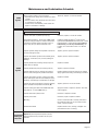
Maintenance and Lubrication Schedule
750
Cycles
Inspect lift for wear, damage or any abnormal
condition
Correct as needed.
Inspect lift for rattles
Correct as needed.
Perform all procedures listed in previous section also
1500
Cycles
Page 14
Platform pivot pin bearings (2)
Platform fold axles (2)
Apply Light Oil - See Lubrication Diagram
Inner roll stop (IB) lever bearings (2)
Apply Light Oil - See Lubrication Diagram
Inner roll stop (IB) lever slot (2)
Rotating pivot slide arm pivot pins (2)
Apply Light Oil - See Lubrication Diagram
Apply Light Oil - See Lubrication Diagram
Parallel arm pivot bearings (16)
Apply Light Oil - See Lubrication Diagram
Handrail pivot pin bearings (4)
Apply Light Oil - See Lubrication Diagram
Hydraulic cylinder bushings (8)
Apply Light Oil - See Lubrication Diagram
Inspect Lift-Tite™ latch rollers for wear or damage,
positive securement and proper operation (2)
Correct, replace defective parts and/or relubricate.
Inspect inner roll stop (IB) for:
• Wear or damage
• Proper operation. Rollstop should just rest on top
surface of the base plate.
• Positive securement (both ends)
Resecure, replace or correct as needed. See
Platform Angle Instructions and Microswitch Adjustment Instructions.
Inspect handrail components for wear or damage,
and for proper operation
Replace defective parts.
Inspect microswitches for securement and proper
adjustment.
Make sure lift operates smoothly
Resecure, replace or adjust as needed. See
Microswitch Adjustment Instructions.
Inspect external snap rings:
• Handrail pivot pins (2 per pin)
• Platform slide/rotate pivot pins (2 per pin)
• Platform fold axles (1 per axle)
• Inner roll stop (IB) lever bracket pins (1 per pin)
• Lift-Tite™ latch gas (dampening) spring (2 per
spring)
Resecure or replace if needed.
Inspect platform fold axles and bearings for wear or
damage and positive securement
Replace defective parts and resecure as needed.
Apply Light Oil.
Apply Light Oil - See Lubrication Diagram
Realign towers and vertical arms. Lubricate or
correct as needed.
Maintenance and Lubrication Schedule
1500
Cycles
Remove pump module cover and inspect:
• Hydraulic hoses, fittings and connections for wear
or leaks
• Harness cables, wires, terminals and connections
for securement or damage
• Control board, circuit breaker, power switch and
lights for securement or damage
Resecure, replace or correct as needed.
Perform all procedures listed in previous section also
Inspect cotter pins on platform pivot pin (2)
Resecure, replace or correct as needed
Hydraulic Fluid (Pump) - Check level. Note: Fluid
should be changed if there is visible contamination.
Inspect the hydraulic system (cylinder, hoses, fittings, seals, etc.) for leaks if fluid level is low.
Use Braun 32840-QT (Exxon® Univis HVI 26)
hydraulic fluid (do not mix with Dextron III or other
hydraulic fluids). Check fluid level with platform
lowered fully and roll stop unfolded fully. Fill
to within 1/2” of the bottom of the 1-1/2” fill tube
(neck).
Inspect cylinders, fittings and hydraulic connections
for wear, damage or leaks
Tighten, repair or replace if needed.
Inspect outer barrier cylinder hose assembly (hose,
fasteners, connections, etc.) for wear, damage or
leakage
4500
Cycles
Tighten, repair or replace if needed.
Inspect parallel arms, bushings and pivot pins for
visible wear or damage
Replace if needed.
Inspect parallel arm pivot pin mounting bolts (8)
Tighten or replace if needed.
Inspect platform pivot pin, bushings and vertical
arms for wear, damage and positive securement
Replace defective parts and resecure as needed.
Apply Light Grease during reassembly procedures.
Inspect upper/lower fold arms, rotating pivot slide
arms, slide support arms and associated pivot pins,
bushings, and bearings for visible wear or damage
Replace if needed.
Inspect gas springs (cylinders) for wear or damage,
proper operation and positive securement (IB)
Tighten, replace or correct as needed
Inspect rotating pivot slide arm UHMW slide bearings (buttons - 2) and UHMW slide (1)
Apply Door-Ease or replace if needed. See Lubrication Diagram.
Resecure or replace if needed.
Inspect vertical arm plastic covers Inspect power cable
Mounting
Resecure, repair or replace if needed.
Decals and Antiskid
Replace decals if worn, missing or illegible. Replace antiskid if worn or missing.
Check to see that the lift is securely anchored to
the vehicle and there are no loose bolts, broken
welds, or stress fractures.
Consecutive Repeat all previously listed inspection, lubrication and maintenance procedures at 750 cycle
750 Cycle
intervals.
Intervals
Page 15
NOTES
This page intentionally left blank to provide a place for notes and references.
Page 16
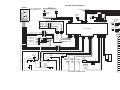
Lift Electrical Schematic
LIFT
SWITCH BOX
BK(24 GA COPPER)
NOTE: ALL WIRES ARE 22 GA.
UNLESS OTHERWISE NOTED.
OR(18)
18)
PK
J15
P28
1 1
2 2
3 3
BU(20)
RD(20)
GN(20)
1 1
2 2
(
WH
P32
P15
NC
C6
STOW INTERLOCK (-)
MICROSWITCH
NO
GN(20)
WH(20)
BU / BK(20)
RD / BK(20)
GN / BK(20)
GN / WH(20)
RD / WH(20)
BU / WH(20)
2
2
12 12
1
1
3
3
6
6
5
5
4
4
7
7
8
8
9
9
10 10
11 11
5
4
3
2
1
6
OR / BK(20)
OR(20)
NC
RD
BK
GN
5
4
3
2
1
6
P8
P9
VT(20)
WH(20)
1 1
2 2
J8
J9
P4
WH(20)
BK(20)
RD(20)
GN(20)
BK(20)
FUSE HOLDER(16)
GN(20)
WH(20)
BN(20)
BU(16)
BU(16)
BU(20)
YL(20)
OR(20)
1
2
3
4
5
6
NO
C
DESCRIPTION
BK(20)
BU(20)
VT(20)
YL(20)
OR(20)
OR(20)
PK(20)
1
2
3
4
5
6
GN(20)
RD(14)
BK(20)
RD(20)
NO
C
WH(26)
BU(26)
BK(26)
YL(26)
RD(26)
GN(26)
STOW INTERLOCK (+)
MICROSWITCH
J31
J25
BU(16)
J3
J4
6
1
5
2
4
3
6
1
5
2
4
3
J7
3
2
1
4
WH(20)
P31
OR(20)
OR / BK(20)
1 1
2 2
P25
BRIDGE
MICROSWITCH
J16
BN(20)
C5
GN(20)
RD(20)
BU(20)
RD(18)
BK(18)
RD(18)
BK(18)
1 1
2 2
J16
BN(20)
GY/RD(18)
BK(20)
YL(26)
RD(26)
GN(26)
S
P16
P16
P7
(GROUND)
YL(26)
RD(26)
GN(26)
S
N
3
2
1
4
OR
P26
OUTER BARRIER
LATCHED
SENSOR
MAGNET
LIFT CONTROL MODULE
RD(20)
BK(20)
LIFT STOWED SIGNAL YL/LT. BU(18)
(GROUND)
(+12V INPUT)
(+12V OUTPUT)
18
15
13
14
7
12
10
11
17
8
9
6
4
5
16
3
1
2
P13
BK(18)
RD(18)
GN(20)
WH(20)
LIFT NOT STOWED SIGNAL YL/LT. BU(18)
VEHICLE SECURE SIGNAL GY/RD(18)
1
2
3
4
5
6
7
8
9
P27
J20
1 1
2 2
J21
1
2
3
4
5
6
7
8
9
MAGNET
N
INTERLOCK
P21
OUTER BARRIER
RAISED
SENSOR
1 1
2 2
P20
1 2 3
1 2 3
1 2 3
1 2 3
BK(18)
RD(18)
2 2
1 1
BK(18)
BK(18)
J13
6
5
4
3
2
1
J20
J6
P20
BK(18)
BK(18)
P26
J27
3
8
6
7
5
4
1
2
6
5
4
3
2
1
PLATFORM LIGHTS (OPTION)
BK(20)
BK / WH(20)
WH / BK(20)
OR
P5
8)
NC
18
15
13
14
7
12
10
11
17
8
9
6
4
5
16
3
1
2
WH
GN
GN
WH
BK
RD
(1
BU
2 2
1 1
WH(20)
BK(20)
C
J5
BK/WH(24 GA SILVER)
BK(24 GA COPPER)
L
G
E
GN / BK(20)
RD / BK(20)
BU / BK(20)
)
(18
WH
C1
NO
RD
BK
WH
GN
J15
P6
RD(18)
P15
3
8
6
7
5
4
1
2
UNFOLD
BU / WH(20)
RD / WH(20)
GN / WH(20)
IB OCCUPANCY
MICROSWITCH
PRESSURE
SWITCH
WH(20)
J32
FOLD
THRESHOLD
SENSOR
P3
GN(18)
BK
DOWN
1 1
2 2
BK(18)
J28
PK
IB JUMPER
RD
UP
BK/WH(24 GA SILVER)
SYMBOL
BATTERY
GY/RD(18)
CHASSIS GROUND
C
LIFT POWER SWITCH
BN(20)
NC
CIRCUIT BREAKER / FUSE
P2
WH(18)
BU(18)
RD(18)
GN(18)
BK(18)
OR(18)
J2-A
7
6
1
5
2
4
3
7
6
1
5
2
4
3
CONNECTORS
WH(26)
BU(26)
BK(26)
YL(26)
RD(26)
GN(26)
JUNCTION
M
MOTOR
SOLENOID
SOLENOID
SWITCH
NO
BRIDGE
SOLENOID
DOWN
SOLENOID
NC
(CIRCUIT BREAKER)
INTERLOCK
LED
GN(20)
GN(20)
CIRCUIT
SENTRY
RD(2)
PUMP BODY
GROUND
THRESHOLD
WARNING
LIGHT
BK
DIODE
00000
J30
RD
BK
GN
FLOOR LEVEL
MEMORY SET
PUSH BUTTON
RD (2)
F
E
D
C
B
A
F
E
D
C
B
A
BU(20)
YL(20)
OR(20)
E
COUNTER
GN
LED
+
-
00000
COUNTER
E
MAGNET
MAGNETIC SWITCH
N
S
LIGHT
WH(20)
POWER
STUD
PRESSURE SWITCH
NEG. -
POS.+
ROTARY
POSITION
SENSOR
GN(20)
FUSE HOLDER(16)
DUAL RELIEF
SOLENOID
GN(20)
IN-LINE
FUSE
(UP)
RD(4)
PUMP BODY
GROUND
GN(20)
RD(14)
HYDRAULIC
GN(14)
GN(20)
GN(20)
M
THRESHOLD
WARNING
BEEPER
BU(20)
BK(6)
PK(20)
PUMP
BK(4)
OR(20)
OR(20)
BK(20)
RD
YL(20)
VT(20)
GN(20)
C
MICROSWITCH
GN(20)
UP/FOLD
SOLENOID
VT(20)
BEEPER
GN(20)
ROTARY POSITION SENSOR
LIFT SHOWN IN STOWED POSITION
Page 17
Li Un
f fo
Sc t E ld
he lec fo
m tri r:
at ca
ic l
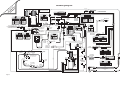
Lift Wiring Diagram
915-4534NA
P20
J20
J20
2
1
5 6
NO.
7
8 9
1
RED
2
BLACK
3
WHITE
4
GREEN
5
NOT USED
6
NOT USED
WHITE(20)
18 17 16 15 14 13 12 11 10
COLOR
RD(20)
BK(20)
RD(20)
BK(20)
P16
J16
1
2
1
2
1
2
NO
NC
N.C.
915-4530RNA
P31
P16
C-H
P4
P9
FS6
P3
3
3
2
1
5 6
6
5
4
1
NC
C-H
COLOR
NO.
10
2
BLUE / WHITE(20)
11
BLUE(20)
3
GREEN / WHITE(20)
12
GREEN(20)
4
NOT USED
13
NOT USED
5
ORANGE JUMPER
14
WHITE(20)
6
ORANGE JUMPER
15
BLACK(20)
NOT USED
COLOR
RED(20)
16
NOT USED
8
ORANGE(20)
17
NOT USED
9
ORANGE / BLACK(20)
18
NOT USED
9
8
7
6
3
2
1
5
4
1
3
2
1
4
3
6
5
4
COLOR
NO.
NOT USED
COLOR
1
OR(20) & OR(20)
2
RED(20) & GREEN(20)
2
YELLOW(20)
1
ORANGE(20)
NO.
3
BLACK(20) & WHITE(20)
3
VIOLET(20)
2
BLUE(20)
4
BROWN(20)
4
BLUE(20)
5
BLACK(20)
6
PINK(20)
12-COND WIRE CODE
NO.
100245-001
3
NOT USED
4
NOT USED
5
WHITE(20)
6
7
VIOLET(20)
NOT USED
8
NOT USED
9
RED(20)
10
BLACK(20)
11
GREEN(20)
12
YELLOW(20)
NO.
COLOR
1
BLACK(20)
BK(20)
2
FUSE HOLDER(16)
2
RED(20)
3
GREEN(20)
3
GREEN(20)
4
WHITE(20)
4
WHITE(20)
5
BROWN(20)
5
BROWN(20)
6
NOT USED
6
NOT USED
6-COND WIRE CODE
WH
BK
OR
Up/Down
Switch
NO.
COLOR
A
NOT USED
B
NOT USED
C
RD
GN
Fold/Unfold
Switch
ORANGE(20)
E
YELLOW(20)
FS13
BU
FS14
1
NO.
GN(20)
L
-
FS20 VT(20)
FS8
FS9
COLOR
NO.
PINK
1
NOT USED
2
RED(20)
3
PINK
3
GREEN(20)
YL(20)
GN(20)
FS21
GN(20)
32929A
J28
P28
Bridge
Microswitch
COM
NO
J25
BU(16)
BU(16)
1
2
VT(20)
Bridge
Circuit Sentry
GN(14)
RL3
Bridge
Down
Dual Relief
A
U
X
B
A
T
Aux.
Back
Plate
BK(20)
BK(6)
3
GREEN(26)
3
GREEN / WHITE(20)
J27
P27
1
P26
J26
1
3 2 1
3-COND WIRE CODE
3-COND WIRE CODE
NO.
COLOR
NO.
1
YELLOW(26)
1
2
RED(26)
2
RED / BLACK(20)
3
GREEN(26)
3
GREEN / BLACK(20)
COLOR
BLUE / BLACK(20)
BU(20)
FS11
1
2
BK(24) COPPER
31221A
BK / WH(24) SILVER
Threshold Sensors
J32
Motor Power Feed Wire
FS2
RD(2)
RED / WHITE(20)
1 2 3
P32
Lift
Power Cable
205-0712-37
RD(2)
BLUE / WHITE(20)
2
Outer Barrier
Latched Sensor
(Side view of
solenoids removed
from pump.)
GN(20)
Bat.
COLOR
1
RED(26)
2
2
1
FS10
(Circuit Breaker)
Lead Wire
13362A
NO.
YELLOW(26)
2
Down
Dual
Relief
22166A BK(4)
BK(20)
RL4
Power
Stud
Connects to
Vehicle Battery
(+) Positive Post
COLOR
1
32645NA60
Ground
BK(20)
NO.
Outer Barrier
Raised Sensor
FS3
GN(20)
3-COND WIRE CODE
BK
Hydraulic
Pump
Pump Ground
RL2
RL1
or
1 2 3
3 2 1
3-COND WIRE CODE
Note polarity of diode. It
must be oriented as shown.
Detail at left shows two different
styles of diode identification.
OR(20)
GN(20)
26082A-4
RD(4)
OR / BK(20)
1
2
FS17
In-Line
Fuse
Pump Module
Power Feed
P25
NC
FS16
7
RL
COLOR
BLUE(20)
31010FA
OR(20)
GN(20)
Up/Fold
Solenoid
1
2
FS5
WH(20)
BK(20)
RD(14)
2
3-COND WIRE CODE
1
IB Jumper
Harness
Threshold
Warning
Light
+
Beeper
BK / WH(24) SILVER
1
Page 18
3
3
OR(20)
FS1
J30
32832A
2
BK(20)
Rotary
Position
Sensor
Floor Level
Memory Set
Push Button
N.C.
C-H
3-COND WIRE CODE
E
FS12
Switch
Box
WH(20)
N.O.
NC
+ -
Counter
BLUE(20)
F
NO
C1
NOT USED
D
COM.
COM
4
BK(20)
RD(20)
WH G
E
FS7
COLOR
IB Occupancy
Microswitch
985-4532NA
6-COND WIRE CODE
COLOR
BLACK(20)
WH
6-COND WIRE CODE
GN(20)
6-COND WIRE CODE
A B C D E F
1
FS4
P8
2
4-COND WIRE CODE
C6
NO.
Interlock LED
PK(20)
J15
1 2
4
COM
NO
N.C.
12 11 10
1
Lift Power
Switch
Stow Interlock (-)
Microswitch
COM.
N.O.
2
RED / WHITE(20)
P7
J16
GN(20)
WH(20)
BN(20)
3
BK(20)
C5
J31
4
1
7
J8
1
2
COM
N.O.
5
WH(20)
Stow Interlock (+)
Microswitch
COM.
RD(20)
6
NO.
GN(20)
BK(20)
915-4539NA
7
RD(20)
1
2
FS5
J21
Lift
Control
Module
J3
J13
J5
J6
J4
GY/RD(18)
P21
8
18-COND WIRE CODE
J9
32639A
YL/LT. BU(18)
32638A
LIFT STOWED / NOT STOWED SIGNAL
(Located in cavity #5, #7 or #9 - see chart above)
P5
J7
Interlock
Connection
GY/RD(18)
VEHICLE SECURE SIGNAL +12V INPUT
P13
GN
NOT USED
9
NOT USED
2
BK(24) COPPER
31221A
2
2
1
BK(24 GA COPPER)
8
NOT USED
RD
NOT USED
LIFT STOWED GROUND SIGNAL
BK / WH(20)
WH
LIFT STOWED +12V OUTPUT
GRAY / RED(18)
BLACK(20)
NOT USED
8
J15
BROWN(20)
6
7
NL916IB/FIB
NL917IB/FIB
NL919IB/FIB
(31033A99)
NOT USED
5
GY / RD(18) VEHICLE SECURE +12V INPUT
7
GN / BK(20)
P15
4
LIFT NOT STOWED GROUND SIGNAL
6
7
6
WH / BK(20)
4
BK / WH(24 GA SILVER)
NOT USED
5
5
BU / BK(20)
3
P15
NOT USED
RD / BK(20)
2
1
P6
COLOR
BK(24 GA COPPER)
3
1
NO.
915-4533NA
NOT USED
2
COLOR
GN(20)
3
3
RD(14)
NOT USED
4
NO.
BN(20)
NOT USED
2
31033A54
NL915IB/FIB
NL918IB/FIB
(31033A96)
1
5
+ -
NOT USED
NOT USED
6
9
4
2
7
6-COND WIRE CODE
7
COLOR
8
BK / WH(24 GA SILVER)
BK(20)
RD(20)
BK(20)
3
4
1
9
4
9 8
NO.
8
5
6 5
COLOR
4
RD(20)
2 1
6
1 2
9-COND WIRE CODE
917-4535RNA-33 REAR PUMP LIFTS
917-4535FNA-33 FRONT PUMP LIFTS
8-COND WIRE CODE
P20
1
9-COND WIRE CODE
Pressure
Switch
FS18
3 2
3
FS19
BK / WH(20)
WH / BK(20)
2 1
2 1
2 1
NO.
Note: All wires 22 GA.
unless otherwise noted.
BK(18)
BK(18)
BK(18)
BK(18)
Platform Lights (Option)
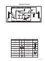
Hydraulic Schematic
.50 GPM
Roll Stop Fold
Pressure Switch
Bridging
Valve
Orifice
Orifice
Lifting
Relief Valve
Down
Valve
Secondary
Valve
2500
PSI
1900
PSI
Opposite
Pump
Cylinder
BACKUP
PUMP
Description
Folding
Relief Valve
Outer Barrier
Cylinder
Pump Side
Cylinder
800
PSI
PUMP
Symbol
Fixed Displacement
Pump
Pump Motor
M
Description
Symbol
Hydraulic Port
M
2 Way 2 Position
Solenoid Valve
Backup Pump
Pressure Compensated
Flow Control
Single Acting Cylinder
Relief Valve
Check Valve
Filter Screen
Unfold Orifice
Vented Reservoir
Manual
Shutoff Valve
Orifice
Pressure Switch
Page 19
Hydraulics Parts List
Part Numbers of Items Dedicated per Lift Model)URQWDQG5HDU3XPS0RGHOV
Item Qty.
Description
NL915
NL916
$ $
NL917
NL919
+RVH$VVHPEO\µ2SSRVLWH3XPS6LGH
+RVH$VVHPEO\µ3XPS6LGH
$
$
$
$ $
3
2
Cylinder C1514.3-9407
C1514.3-9408
C1514.3-9408
C1514.3-9407 C1514.3-9408
4
1
(Rear Pump) Hose Assembly, 3/16” w/Two Guards
915-2601-123 915-2601-139 915-2601-139 915-2601-123 915-2601-139
5
1
(Front Pump) Hose Assembly, 3/16” w/Two Guards
6
1
(Front Pump) Hose Assembly, 3/16”
915-5602-82
$
NL918
915-5602-92.5
915-5602-92.5
915-5603-80.5 915-5603-83.5
915-5603-86.5
$ $
915-5602-82
915-5602-92.5
915-5603-83.5 915-5603-86.5
Part Numbers of Items Identical on all Lift Models)URQWDQG5HDU3XPS0RGHOV
Item Qty.
Description
Part No.
9
3XPS$VVHPEO\09ZLWK5HVHUYRLUZLWK%DFNXS3XPS
8
1
6ROHQRLG8S3RVW7URPEHWWD)ODW0RXQW
9
1
Power Cable, Up Solenoid to Motor
29049
0RWRU3XPS9ROW/RZ530
(OERZ0DOH6$(25LQJWR6$(25LQJ%RVV
9DOYH$VVHPEO\´'RZQ%ULGJHµFRPSOHWH
&RLORQO\´'RZQ%ULGJHµ9DOYHVKRZQEHORZ
&DUWULGJHRQO\´'RZQ%ULGJHµ9DOYHVKRZQEHORZ
9DOYH$VVHPEO\´'XHO5HOLHIµFRPSOHWH
. &DUWULGJHRQO\´'XHO5HOLHIµ9DOYHVKRZQEHORZ
&DS5HVHUYRLU)LOOHU
25LQJRQO\+DQG3XPS0RXQWLQJ
+DQG3XPS%DFNXSZLWK25LQJV,WHP
20
3
Screw, 1/4-20 x 2-1/4”, Allen Head
26080
&ODPS5HVHUYRLU+0
5HVHUYRLU+\GUDXOLF)OXLG
)LWWLQJµ137[µ%DUE3ODVWLF
24
1
Switch, Pressure, 7/16-20 SAE O-Ring Male
31199
25
2
Fitting, Male 7-16-20 SAE O-Ring to Male 7/16-20 JIC 37°
24504
(OERZ)HPDOH-,&6ZLYHO0DOH-,&
(OERZ6$(25LQJ0DOH-,&0DOH2ULÀFH
(OERZµ1370DOHWRµ%DUEHG
+RVH7KHUPDO3ODVWLF%ODFNµ,'
&RQQHFWRU3ODVWLF´<µµ2'
31
1
Fitting, 90° - Male 9/16-18 SAE O-Ring to Male 7/16-20 JIC 37°
32
1
Cylinder, Roll Stop
.
87622
25309-05A
33
1
Handle with Grip
'LRGH$VVHPEO\8S6ROHQRLG
$
%UHDWKHU9HQWµ137
.LW+\GUDXOLF3RUW6HUYLFH&DS
.
17206A
12
“Down and Bridge”
Valve (complete)
15
“Duel Relief”
Valve (complete)
13
13
Coil
#31122
Coil
#31122
Hydraulic Fluid
When adding or changing
K\GUDXOLFÁXLGXVH%UDXQ
32840-QT (Exxon®8QLYLV
+9,K\GUDXOLFÁXLGdo
not mixZLWK'H[WURQ,,,RU
RWKHUK\GUDXOLFÁXLGV
Page 20
5 Seal Kits: If repairing a cylinder, order Seal Kit #1500-0500P.
5DZPDWHULDOLWHPVRUGHUHGDQGSULFHGSHULQFKRUGHUVSHFLÀHGOHQJWK
14
Cartridge
#26078
16
Cartridge
#24612
7
36
3
6
FRONT PUMP
Hydraulics Diagram
3
Hydraulic
Repair
9
For repair of a
hydraulic hose
or cylinder, read
this.
Service
Bulletin
27049
5
34
32
25
10
11
12
27
REAR PUMP
FRONT PUMP
8
24
33
4
27
15
17
Roll Stop Cylinder
31
18
35
26
19
20
21
Manual
Backup
Pump
23
22
Hydraulic
Pump
29
28
30
1
2
Pump Side Cylinder
Opposite Pump Side Cylinder
25
28
29
29
Page 21
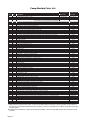
Pump Module Parts List
3DUW1XPEHUVRI,WHPV'HGLFDWHGSHU/LIW0RGHO
Item
Qty.
Description
3XPS0RGXOHFRPSOHWH9ROW5HDU
3ODWH%DFNLQJ0RXQWLQJ5HDU
&RYHU3XPS3LHFH%DFN%RWWRP51$37RU)1$37,QFOXGHV,WHPVDQG
&RYHU3XPS3LHFH7RS)URQW51$37RU)1$37,QFOXGHV,WHPVDQG
Item
5
8
9
11
12a
12b
12c
14
16
17
19
22
26
29
30
32
34
37
38
40
41
42
44
Qty.
1
2
2
1
8
1
1
1
3
2
1
1
1
1
1
1
1
1
1
1
Description
3XPS$VVHPEO\09*'XDO5HOLHI$56,QFOXGHV,WHPV
Power Cable, Up Solenoid to Motor
6ROHQRLG8S3RVW7URPEHWWD)ODW0RXQW
'LRGH$VVHPEO\8S6ROHQRLG
Nut, #10-32, Serrated Flange
Fitting, Male 7/16-20 O-Ring to Male 7/16-20 JIC 37°
(OERZ)HPDOH6ZLYHO-,&WR0DOH-,&
Switch, Pressure
&RQWURO+DQG3HQGDQW$VVHPEO\6HHEHORZIRUDYDLODEOHRSWLRQV
Control, Hand Pendant Assembly - Non-Shielded Cable - Straight tSee note below
Control, Hand Pendant Assembly - Shielded Cable - Straight tSee note below
Control, Hand Pendant Assembly - Shielded Cable - Coiled tSee note below
&RQWURO%RDUG$VVHPEO\
Standoff, Snap-In
6ZLWFK3XVK%XWWRQ
Recepticle, Clip On
Lens, Threshold Warning - Red
'HFDO:DUQLQJ3UHVVXUH5HOLHI9DOYH1RWVKRZQ
Spacer, Lens - NHTSA
0HWDO5LQJ%DVH/DPS
6RFNHW/DPS
Screw, #8-32 x 1/2” Pan Head Phillips - Thread Cut
%XOE/LJKW
'LRGH*UHHQ/('3DQHO0RXQW
5LYHW6QDSµ+ROH[µµ7KLFN
Washer, 5/16” Flat
%ROW[µ1\ORFN+H[6HHQRWHEHORZ
%ROW[µ1\ORFN+H[6HHQRWHEHORZ
Cable, Ground
Washer, 5/16” External Tooth
%HHSHU&RQWLQXRXV
Switch, Toggle
'HFDO/LIW3RZHU2Q2II1RWVKRZQ
Stud, Power Feed
5XEEHU%RRW5HGtSee note below
+DUQHVV/LIW,QWHUORFN&RQQHFWLRQ Wire Assembly, Lift Stowed Connection tSee note below
Pump Handle with Grip
5LYHW3RS6'%6µµµ
Plug, Window - Clear
Stud, Wing Head - 1/4 Turn
Retainer, Push On
:DVKHU1\ORQµ,'[µ2'[µ
Clip, Pump Handle - Top
&OLS3XPS+DQGOH%RWWRP
'HFDO0DQXDO,QVWUXFWLRQV3XEOLF1RWVKRZQ
'HFDO5HPRYDO,QVWDOODWRQ3XPS&RYHU1RWVKRZQ 'HFDO:DUQLQJ&RQWURO%RDUG'DPDJH(6'1RWVKRZQ
'HFDO5HPRYDO,QVWDOODWLRQ3XPS+DQGOH1RWVKRZQ 'HFDO,QVWDOODWLRQ:DUQLQJ+\GUDXOLF3UHVVXUH6ZLWFK1RWVKRZQ
'HFDO'XDO5HOLHI$GMXVWPHQW1RWVKRZQ
'HFDO/&'/LIW&RGHV1RWVKRZQ &DEOH3XPS0RGXOH3RZHU+RRNXS1RWVKRZQ
+DUQHVV3RZHU6WRZ,QWHUORFN1RWVKRZQVHH:LULQJ'LDJUDP
+DUQHVV,QWHUORFN/LJKWLQJ1RWVKRZQVHH:LULQJ'LDJUDP
+DUQHVV8S'RZQ6ROHQRLG1RWVKRZQVHH:LULQJ'LDJUDP
+DUQHVV7KUHVKROG6ZLWFK([WHQVLRQ1RWVKRZQVHH:LULQJ'LDJUDP
+DUQHVV+DQG&RQWURO3XPS+RXVLQJWR&LUFXLW%RDUG1RWVKRZQVHH:LULQJ'LDJUDP
NL915IB, NL916IB,
NL917IB, NL918IB
and NL919IB
NL915FIB, NL916FIB,
NL917FIB, NL918FIB
and NL919FIB
51$
51
915-0513RNPT
915-0519RNPT
)1$
)1
915-0513FNPT
915-0519FNPT
Part Numbers of Items Identical on all Lift Models
Part No.
9 29049
$ 83080
24504
31199
32832A
32833A
32421A
31011
28803
30704
31386
30974
10063
22166A
16368
31787
26084
82046
$
32638A
17206A
30443
28804
28805
915-5517
$
51$
1$
1$
1$
*$SSO\UHG7KUHDG/RFNHU/RFWLWH®WRWKHIRXUKH[EROWVLWHPVDQGLIDEOXHQ\ORQSDWFKLVQRWSUHVHQWRQ
WKHEROWVZKHQUHWURÀWWLQJDQ0SXPSDVVHPEO\/RFWLWH®LVDYDLODEOHIURP7KH%UDXQ&RUSRUDWLRQXQGHUSDUW
number 11522-1.
t,QGLFDWHVLWHPVDYDLODEOHIRUUHSODFHPHQWSDUWSXUSRVHVonly. These items are not included with replacement pump
modules.
Page 22
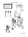
Pump Module Diagram
43
Pump Mounting Bolts
39
$SSO\UHG7KUHDG/RFNHU/RFNWLWH®
to the three pump mounting bolts (items
DQGLIDEOXHQ\ORQSDWFKLVQRW
SUHVHQWRQWKHEROWVZKHQUHWURÀWWLQJDQ
M268 pump assembly. Loctite® is
DYDLODEOHIURP7KH%UDXQ&RUSRUDWLRQ
under part number 11522-1.
44
40
41
42
38
3
45
12a
32819
DO
12b
39
12c
WN
32819
UP
DO
WN
LD
UP
FO
UN
LD
FO
WN
DO
UP
OLD
UNF
D
FOL
32820
UNF
®
D
FOL
32820
OLD
17
®
3
3235
23
19
24
2
20
22
16
21
13
26
27
28
14
29
30
15
31
32
1
4
9
25
35
5
34
11
8
37
36
7
28
6
8
9
10
Note: Rear pump shown,
front pump mirror image.
Page 23
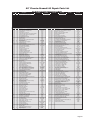
42” Floor-to-Ground Lift Repair Parts List
Part Numbers of Items Dedicated per Lift Model
Item
Qty.
4
14
1
1
Item
Qty.
23
24
29
30
37
42
43
48
52
59
71
80
87
88
89
1
1
1
1
1
1
1
2
2
2
2
2
2
2
2
Description
NL915IB
%DVH:HOGPHQW
&RYHU3XPS3LHFH%DFN%RWWRP
&RYHU3XPS3LHFH7RS)URQW$VV\
Platform Weldment
2XWHU%DUULHU
,QQHU5ROOVWRS
%ULGJH6ZLWFK$VVHPEO\
3ODWH%DFNLQJ0RXQWLQJ5HDU
%DVH&RYHU
3DUDOOHO$UP$VV\%RWWRPZ%HDULQJV5HDU
3DUDOOHO$UP$VV\7RSZ%HDULQJV)URQW
3DUDOOHO$UP$VV\7RSZ%HDULQJV5HDU
3DUDOOHO$UP$VV\%RWWRPZ%HDULQJV)URQW
Rubber Nose
NL915FIB
51:
5137
5137
917-03050NW
5<
1:<
)$
51
&1$<
1$
)$
51$
1$
24603-30
NL918IB
)1:
)137
)137
917-03050NW
)<
1:<
)$
)1
&1$<
1$
)1$
5$
1$
24603-30
51:
5137
5137
917-03350NW
5<
1:<
)$
51
&1$<
1$
)$
51$
1$
24603-33
NL918FIB
)1:
)137
)137 917-03350NW
5< 1:<
)$
)1 &1$<
1$ )1$ 5$ 1$ 24603-33
Part Numbers of Items Identical on All Lift Models
Page 24
Description
%ORFN3ODWIRUP6WRS
%ORFN3ODWIRUP6WRS
6QDS5LQJ
25LQJ,'[2'
6FUHZ6RFNHW+HDG[ZLWK6KRXOGHU
*URPPHW,')5[*'7
3LYRW2XWHU%DUULHU/HYHU
5LYHW3RS[
Stud, Wing Head
Retainer, Push-On
*URPPHW,')5*'7
3XPS$VVHPEO\
3LQ3LYRW3DUDOOHO$UP
6FUHZ'ULYH[/RQJ%ODFN
Receptacle, Clip-On
Cylinder, Flap
6QDS5LQJ
/DWFK2XWHU%DUULHU
%ROW[1\ORFN+H[
:DVKHU)ODW
%ROW[1\ORFN+H[
$VVHPEO\,%2FFXSLHG
Assembly, Rotary Position Sensor
%ROW[1\ORFN+H[
5LYHW3RS6'%6/)
5LYHW3RS
%HDULQJ)ODQJH[
Weldment, Latch, Lift/Tite, Rear
Weldment, Latch, Lift/Tite, Front
6FUHZ[5RXQG+HDG
6FUHZ[)ODW+HDG&RXQWHUVLQN
6FUHZ[0DFK7UXVV+HDG
1XWZ/RFNZDVKHU
Nut, #8-32, Hex
%DJ9LQ\O[
&\OLQGHU5HWUDFWHG
6FUHZ[3DQ+HDG3KLOOLSV7KG&XW
Washer, External Tooth
&ODPS&ORVHG,QVXODWHG
9HUWLFDO&KDQQHO:HOGPHQW)URQW
&RYHU3ODVWLF3DUDOOHO$UP26)URQWZ7DSH
7DSH:LGH6)DFH)RDP[6KRZQ
7DSH:LGH6)DFH)RDP[6KRZQ
&\FOH&RXQWHU/&':LWKRXW5HVHW
Handrail Weldment
5LYHW3XVK,Q00
%XPSHU5XEEHU2'
6FUHZ[6HOI7DS3KLOOLSV
%XOE/LJKW:+DORJHQ5HÁHFWRU
1XWZ/RFNZDVKHU
6FUHZ[%XWWRQ+HDG6RFNHW&DS
:DVKHU)ODW%ODFN
1XW+H[/RFN
&RWWHU3LQ[%ODFN
1XW+H[/RFN
&RYHU3ODVWLF3DUDOOHO$UP,6)URQWZ7DSH
Threshold Strip Switch
%ROW6KRXOGHU[
:DVKHU,'[2'[$XWR%.
:DVKHU)ODW%ODFN=LQF
%ROW[+H[
:DVKHU/RFN%ODFN
/HYHU,QQHU5ROOVWRS
&ODPS,QVXODWH,'
:DVKHU/RFN%ODFN
Gas Spring, Fold Arm
%DOO6WXG*DV6SULQJ00[)7KUHDG
:DVKHU/RFN
6SDFHU)ODS&\OLQGHU7KLFN
&OLS6DIHW\[)ODQJH
%ROW;)ODQJH%XWWRQ+HDG6RFNHW&DS
%ROW[)ODQJH+H[
Nut, 5/16-18, Serrated Flange
Arm, Slide Support
Slide, Platform, Rotate, Weldment
6SDFHU2'[,'[/*
%HDULQJ)ODQJH[
:HOGPHQW3ODWIRUP3LYRW$UP
3LQ3LYRW/RZHU$UP
5LQJ6QDS([WHUQDO
%HDULQJ8+0:)ODW
%DOO6WXG00
9HUWLFDO&KDQQHO:HOGPHQW5HDU
3ODVWLF(QG&DS,'[2'
*ULS+DQGOH<HOORZ
Part No.
28804
28805
9
%.
28803
25309-05A
1$
$
31094A
27013RW
27013FW
%.
10777
&
83588
)1:
1$
5
5
985-4618NW
%.
1$
31221A
%.
1
29186
25131
985-0612N
915-0606N
1:%.1
1
51:
Item
Qty.
105
108
113
118
122
136
142
143
176
177
2
1
4
1
1
1
2
2
1
1
Description
6SULQJ'DPSHQHU5HWUDFW
%ROW[/RZ6RFNHW+G&DS%N
%XPSHU[/RQJ
6FUHZ[6HW/RFN%ODFN
%ORFN*XLGH3ODWIRUP6WRZ
Pin, Platform
6FUHZ[6+)6
6SDFHU8+0:9HUWLFDO&KDQQHO
Position Sensor Collet
%UDFNHW0RXQWLQJ4XLHW5LGH
*DV6SULQJ([WHQGHG&RPSUHVVHG
%ROW[&DUULDJH%ODFN
:DVKHU([WHUQDO7RRWK
Nut, 5/16-18 Hex
%UDFNHW,QQHU6LGH3DQHO*XLGH
%HDULQJ8+0:)ODW7KLQ%ODFN
3LYRW,QQHU5ROOVWRS/HYHU8SSHU,QVLGH
%HDULQJ)ODQJH[
Spacer, UHMW, Latch
6SULQJ[([WHQVLRQZ+RRNV
7XELQJ3RO\XUHWKDQH,'[2'[
3LQ&OHYLV[%ODFN
Pin, Platform Cylinder
5LQJ6QDS([WHUQDO7KLFN
:HOGPHQW7XEH,%)ROG$UP)URQW
/HYHU2XWHU%DUULHU/DWFK$VVHPEO\$
1XW+H[
:HOGPHQW7XEH,%)ROG$UP5HDU
3LYRW2XWHU%DUULHU&\OLQGHU)URQW
%ROW[+H[+HDG&DS
%ROW[6+&6Z1\ORFN3DWFK
6FUHZ[)ODW+HDG+H[
$GDSWHU&\OLQGHU2XWHU%DUULHU/HYHU2XW
%ROW[%XWWRQ+HDG6RF&DS+G
5LYHW3RS%ODFN
$GDSWHU&\OLQGHU2XWHU%DUULHU/HYHU
Harness, Sensor - Cherry w/Plug
5LYHW6QDS%ODFN7KLFN
&OLS&DEOH3ODVWLF
1XW7RS/RFN%ODFN
%ROW[%XWWRQ+HDG6RFNHW
%ROW[+H[+HDG&DS
Roller Assembly
Roller Retainer
1XW+H[/RFN
3LYRW,QQHU5ROOVWRS/HYHU8SSHU2XWHU
&ODPS,'1\ORQ/RRS
:DVKHU)ODW$XWR%.
5LYHW6QDS[
%HDULQJ)ODQJH[)'8
&RYHU3ODVWLF3DUDOOHO$UP265HDUZ7DSH
:HOGPHQW,QQHU5ROOVWRS%UDFNHW)URQW
6SDFHU+DQGUDLOµ7KN8+0:
:DVKHU,'[2'[%ODFN
&RYHU3ODVWLF3DUDOOHO$UP,65HDUZ7DSH
:HOGPHQW,QQHU5ROOVWRS%UDFNHW5HDU
6SULQJ7RUVLRQ,'[
6SDFHU,%/RFN
:HOGPHQW,%/RFN
%HDULQJ,'[/RQJ
5ROOHU2'[/RQJ
(&OLS6KDIW
6SDFHU+DQGUDLO7KN8+0:
$GDSWHU&\OLQGHU2XWHU%DUULHU/HYHU
+DUQHVV6HQVRU0DJQHWLFZ3OXJ
5LYHW3RS6'%6
%HDULQJ)ODQJH[3ODVWLF
/LJKW$VV\9HUWLFDO&KDQQHO
7DE2XWHU%DUULHU)ODS&\OLQGHU
:DVKHU,'[2'[
6SDFHU8+0:2'[,'[
%ROW[6RF+G&DS6FUHZ%N
6SDFHU)ODS&\OLQGHU7KLFN
*XDUG2XWHU%DUULHU6HQVRU:LUHV
:DVKHU)LQJHU'LVF6SULQJ
6FUHZ[%XWWRQ+HDG6RFNHW&DS
Position Sensor Spacer
Slide, UHMW, Platform Rotate
Part No.
975-2325
31093
%.
10058
950-7760
5
%.
915-0414
51:
%.
)1$
1
32645NA60
%.
1000-2395A
915-5353
%.
1$
)1:
1$
51:
1:
1
$
$ 1$
1<
:3
31092
31677
42” Floor-to-Ground Lift Exploded View
98
36
112
109
72
11
98
49
74
147
106
111
104
113
148
134
98
72
50
9
74
73
28
38
29
113
79
98
37
34
114
106
174
27 73
28
31
27
33
8
31
73
112
42
174
73
26
23
74
18
106
43
64
18
17
100
17
17
100 28
27
17
28
27
134
147
78
55
148
36
58
24
138
138
78
74
148
146 148
106
56
165
13
167
146
2
33
27
36
112
1
111
109
70
71
65
104
134
113
106
148
28
74
175
52
3
63
148
134
35
138
71
106 74
52
60
177
27
53
89
28
134
12
94
78
78
58
93
94
147
74
60
106
148
57
67
87 148
152
91
88
91
134
146
138
60
27
138
28
114
115
77
85
113
176
174
116
79
73
91
141
153 31
152
86
6
69
62
47
44 80
41
108
85
170
138
170
115
50
99
148
60
90
61
98
102
130
148
59
110
154
7
54
85
146
84
28
79
148
167
45
148
138 148
74
106
92
91
175
146
138
148
10
95
138
150
106
148
27
67
149
94
117
155
77
93
91
94
152
67
148 74
106
153
76
41
40
16
40
25
141
126
79
99
122 123
20
33
138
148
90
152
87
130
157
40
149
83
136
61
165
98
84
82
119
137
166
169
97
159
158 129
81
19
128
118
161
124
145
131
66
76
41
135
131
132
32
5
121
30
160
22
120
80
144
4
173
107
30
160
166
171
172
59
159
157
156
121
40
123
61
85
68
142
62
60
60
161
143
101
91
170
66
20
91
31
75
76
145
139
103
27
60
19
127
162
142
105
117
141
86
159 158
144
141
57
88
160
161
117
143
162
28
129
96
101
149
60
89
91
15
139
74
160
94
117
48
102 73
94
159
149
46
116
174
161
156 157
157
107
48
148
28
82
110
67
126
103
138
92
76
96
57
63
81
33
115
27
146
68
151
21
168
51
163
22
132 131
125
14
41
61
39
75
Page 25
42 Un
” fo
Ex F- ld
p T- fo
V lod G L r:
ie e if
w d t
48” Floor-to-Ground Lift Exploded View
133
98
112
109
72
11
98
49
98
74
113
148
73
106
134
53
74
163
28
27 163
38
37
34
106
43
64
28
174
27
33
8
174
163
112
42
58
53
163
26
18
114
50
9
29
138
17
100
17
17
100 28
27
17
28
27
134
18
73
78
55
148
36
138
74
106
24
164
148
146 148
78
106
56
167
27
133
134
35
112
111
14
70
71
65
104
134
113
106
148
28
74
175
52
3
63
148
1
109
138
71
106 74
52
22
94
58
89
134
12
78
78
138
94
67
87
152 28
88
152
115
77
85
113
153
174
86
91
57
106
60
60
99
85
170
62
115
50
74
148
60
90
6
69
148
27
91
138
141
163
53
116
79
134
148
91
91
114
60
147
28
27
146
93
73
176
74
146
2
33
111
104
98
72
23
113
79
41
108
138
47
148
102
61
130
44
110
98
154
54
7
85
146
28
13
167
45
148
138 148
74
106
91
103
138
175
146
138
148
148
28
27
67
102
107
48
148
149
48
101
46
116
53
163
149
15
95
138
150
106
74
149
60
94
94
141
86
88
155
77
174
91
148
94
152
67
106
91
74
41
40
25
126
140
16
79
122 123
20
143
142
123
91
87
60
61
68
85
59
130
149
107
157
160
84
159
160 158 129
161
124
164
98
82
137
97
75
Page 26
165
137
169
128
118
145
32
61
39
21
10
31
51
132
41
125
135
131
132
5
166
121 168
30
81
131
66
76
4
61
30
119
19
173
136
83
120
80
144
178
171
172
159
157
166
62
60
156
40
101
90
161
121
40
138 148
152
170
40
76
33
99
145
20
91
153
41
165
131
160
129
19
127
139
103
27
60
159 158
144
140
57
91
160
161
162
142
105
162
28
96
143
117
89
93
117
159
94
117
117
139
161
156 157
157
67
126
92
82
110
92
76
96
57
63
68
81
33
115
27
146
80
151
79
148
84
75
76
66
59
48” Floor-to-Ground Lift Repair Parts List
Part Numbers of Items Dedicated per Lift Model
Item
Qty.
1
2
3
4
5
6
7
8
9
10
11
12
13
14
1
1
1
1
1
1
1
1
1
1
1
1
1
1
Item
Qty.
Description
NL916IB
Base Weldment
Cover, Pump, 2-Piece, Back-Bottom
Cover, Pump, 2-Piece, Top-Front
Platform Weldment
Outer Barrier
Inner Rollstop
Bridge Switch Assembly
Plate, Backing/Mounting
Base, Cover
Rubber Nose
Parallel Arm Assy.,Top-Front w/Bearings
Parallel Arm Assy.,Top Rear w/Bearings
Parallel Arm Assy., Bottom Rear w/Bearings
Parallel Arm Assy., Bottom Front w/Bearings
NL916FIB
985R5148NW30
915-0513RNPT
915-0519RNPT
917-03050NW
915R4312-30Y
915-0147NW30Y
31010FA
985-2501RN
975-3148CNA30Y
24603-30
915-0437FA
917-5437RNA
917-4458RNA
917-4458FNA
NL917IB
985F5148NW30
915-0513FNPT
915-0519FNPT
917-03050NW
915R4312-30Y
915-0147NW30Y
31010FA
985-2501FN
975-3148CNA30Y
24603-30
985-5437FNA
917-0436RNA
917-4457NA
975-4458NA
985R5148NW33
915-0513RNPT
915-0519RNPT
917-03350NW
915R4312-33Y
915-0147NWY
31010FA
985-2501RN
975-3148CNA33Y
24603-33
915-0437FA
917-5437RNA
917-4458RNA
917-4458FNA
NL917FIB
985F5148NW33
915-0513FNPT
915-0519FNPT
917-03350NW
915R4312-33Y
915-0147NWY
31010FA
985-2501FN
975-3148CNA33Y
24603-33
985-5437FNA
917-0436RNA
917-4457NA
975-4458NA
NL919IB
985R5148NW34
915-0513RNPT
915-0519RNPT
919-03450NW
915R4312-34Y
915-0147NW34Y
31010FA
985-2501RN
975-3148CNA34Y
24603-34
915-0437FA
917-5437RNA
917-4458NA
917-4458FNA
NL919FIB
985F5148NW34
915-0513FNPT
915-0519FNPT
919-03450NW
915R4312-34Y
915-0147NW34Y
31010FA
985-2501FN
975-3148CNA34Y
24603-34
985-5437FNA
917-0436RNA
917-4457NA
975-4458NA
Part Numbers of Items Identical on All Lift Models
15
16
17
18
19
20
21
22
23
24
25
26
27
28
29
30
31
32
33
34
35
36
37
38
39
40
41
42
43
44
45
46
47
48
49
50
51
52
53
54
55
56
57
58
59
60
61
62
64
65
66
67
68
69
70
71
72
73
74
75
76
77
78
79
80
81
82
83
84
85
86
87
88
89
90
91
92
93
94
95
96
97
98
99
1
1
4
4
2
2
1
1
1
1
1
1
10
10
1
1
1
1
4
2
2
1
1
2
1
4
4
1
1
2
2
1
2
2
1
2
1
2
4
1
1
2
6
1
2
8
4
2
2
2
2
4
2
2
1
2
2
3
10
2
6
2
4
4
2
2
2
1
2
6
2
2
2
2
2
10
2
2
6
2
2
1
6
2
Description
Block, Platform Stop - Bridging - Rear
Block, Platform Stop - Bridging - Front
Snap-Ring 5/16"
O-Ring, 5/16" I.D. x 1/16" O.D.
Screw, Socket Head, 3/8-16 x 1/2" with 1/2" Shoulder
Grommet, I.D. .281"/ FR.125" x GD.625"/T.375"
Pivot, Outer Barrier Lever
Slide, UHMW, Platform Rotate
Stud, Wing Head
Retainer, Push-On
Grommet, ID .312", FR .250", GD .813" T500"
Pump Assembly
Pin, Pivot, Parallel Arm
Screw Drive #8 x 3/16" Long Black
Receptacle, Clip-On
Cylinder, Outer Barrier
Screw, 10-32 x 5/8" Pan Head Phillips, Thd. Cut
Latch, Outer Barrier w/Magnet
Bolt, 5/16-18 x 1/2" Nylock, Hex
Washer, 5/16" Flat
Bolt, 3/8-16 x 1/2" Nylock, Hex
Assembly, IB Occupied
Assembly, Rotary Position Sensor
Bolt, 5/16-18 x 3/4" Nylock, Hex
Rivet, Pop, SD68 BSLF-3/16" - .38"/.50"
Rivet, Pop, 1/8"- .25"/.31"
Bearing, Flange, 1/2" x 1/4"
Weldment, Latch, Lift/Tite, Rear
Weldment, Latch, Lift/Tite, Front
Screw, #4-40 x 5/8", Round Head
Screw, 1/4-20 x 3/4", Flat Head, Countersink
Screw, #8-32 x 1", Mach. Truss Head
Nut, #4-40 w/Lockwasher
Nut, #8-32, Hex
Bag, Vinyl - 7" x 10"
Cylinder, 14.625"/29.146" Retracted
Adapter, Cylinder/Outer Barrier Lever
Washer, External Tooth
Washer, Finger, Disc Spring
Vertical Channel Weldment, Front, 48"
Cover, Plastic, Parallel Arm, O/S Front-w/Tape
Tape, 1" Wide S-Face Foam, x 14" (1 Shown)
Tape, 1" Wide S-Face Foam, x 10" (3 Shown)
Cycle Counter-LCD Without Reset
Handrail Weldment
Rivet, Push In - 8MM
Bumper, Rubber, 31/32" O.D.
Screw, #8-18 x 1/2", Self-Tap, Phillips
%XOE/LJKW:+DORJHQ5HÁHFWRU
Nut, #10-32 w/Lockwasher
Screw, 1/4-20 x 3/4", Button Head, Socket Cap
Washer, 3/8" Flat, Black
Nut, 3/8-16, Hex Lock
Cotter Pin, 1/4" x 2", Black
Nut, 1/4-20 Hex Lock
Cover, Plastic, Parallel Arm, I/S Front-w/Tape
Threshold Strip Switch
Bolt, Shoulder, 5/16 x 5/8-1/4"-20
Washer, #10, Flat, Auto BK
Washer, 1/2" Flat Black Zinc
Bolt, 3/8-16 x 1", Hex
Washer, 3/8", Lock, Black
Lever, Inner Rollstop
Clamp, Insulate, 1 3/8" I.D.
Washer, 5/16" Lock, Black
Gas Spring, Fold Arm
Ball Stud, Gas Spring, 13MM x 3/8-16 F. Thread
Washer, 3/8", Lock
Spacer, Flap Cylinder .184" Thick
Clip, Safety, 3/8-16 x 3/4", Flange
Bolt, 3/8-16 X 3/4", Flange Button Head, Socket Cap
Bolt, 5/16-18 x 2", Flange, Hex
Nut, 5/16-18, Serrated Flange
Arm, Slide Support
Slide, Platform, Rotate
Spacer, .5" O.D. x .334" I.D. x 1.515" LG
Bearing, Flange, 3/4" x 1/4"
Weldment, Platform Pivot Arm - 48"
Pin, Pivot, Lower Arm
Ring, Snap, 3/4", External
Bearing, UHMW, Flat, 1.226"
Ball Stud, 10MM
Vertical Channel Weldment, Rear, 48"
Plastic End Cap, 1" I.D. x 1 1/4" O.D.
Grip, Handle, Yellow
Part No.
Item
Qty.
25778
900-0311
24570
26614
25929
27725
24550
31677
28804
28805
27726
31038-12V
917-0403
31086BK
28803
25309NA
26714
915-4343NA
10012
10063
29729
32642A
31094A
29608
15244
13906
24442
27013RW
27013FW
14810
28986
19912BK
19537
10777
31174
C1514.3-9408
915-0344
83588
27276
955-0448FNW
915-0704NA
82015R014
82015R010
30547
985-4618NW
30063
10950
13583
18349
81068-000
10064
13617
15886BK
10775
915-0701NA
31221A
31816
11541
25346
10025
10069BK
985-0404N
29765
10068
29186
29185
10069
915-0416
12608
25171
25130
25131
985-0612N
985-0606N
25132
24012
985-0640NW-BKN
900-0413N
18657
205-1760
21301
955-0448RNW
20474
19074
100
101
102
103
104
105
106
107
108
109
110
111
112
113
114
115
116
117
118
119
120
121
122
123
124
125
126
127
128
129
130
131
132
133
134
135
136
137
138
139
140
141
142
143
144
145
146
147
148
149
150
151
152
153
154
155
156
157
158
159
160
161
162
163
164
165
166
167
168
169
170
171
172
173
174
175
176
177
2
2
2
2
2
2
10
2
1
2
2
2
3
4
2
3
2
4
1
1
1
2
1
2
1
1
4
1
1
2
2
4
3
2
6
1
1
4
11
2
2
2
2
2
2
2
6
1
18
4
1
1
4
2
1
1
2
4
2
4
4
4
2
8
3
2
2
2
1
1
4
1
1
1
4
4
1
4
Description
Spring, Dampener, Retract
Bolt, 5/16-18 x 1 1/4" Low Socket Hd., Cap, Bk.
Bumper, .75"x .625" Long
Screw, 1/2-20 x 1 1/2" Set Lock, Black
Block, Guide-Platform Stow
Pin, Platform
Screw, 5/16-18 x 3/4", SHFS
Spacer, UHMW, Vertical Channel
Position Sensor Collet
Bracket, Mounting, Quiet Ride
Gas Spring, 12.2" Extended/8.3" Compressed
Bolt, 5/16-18 x 3/4", Carriage, Black
Washer, 5/16", External Tooth
Nut, 5/16-18 Hex
Bracket, Inner Side Panel Guide
Bearing, UHMW, Flat, Thin, Black
Pivot, Inner Rollstop Lever, Upper, Inside
Bearing, Flange - 3/4" x 1/2"
Spacer, UHMW, Latch
Spring, 1/4" x 1" Extension w/Hooks
Tubing, Polyurethane - 1/4" I.D. x 1/2" O.D. x .81"
Pin, Clevis, 3/8" x 3", Black
Pin, Platform Cylinder
Ring, Snap, 1/2", External, .035" Thick
Weldment, Tube-IB Fold Arm-Rear
Lever, Outer Barrier Latch (Assembly #915-0345A)
Nut, 3/8-16, Hex
Weldment,Tube-IB Fold Arm-Front
Pivot, Outer Barrier Cylinder, Front
Bolt, 5/16-18 x 1 1/2" Hex Head, Cap
Bolt, 7/16-20 x 1", SHCS, w/Nylock Patch
Screw, #10-32 x 3/8", Flat Head, Hex
Adapter, Cylinder/Outer Barrier Lever-Out
Bolt, 5/16-18 x 3/4", Button Head, Soc Cap Hd
Rivet, Pop, 3/16"-.25"/.38", Black
Adapter, Cylinder/Outer Barrier Lever
Harness, Sensor - Cherry w/Plug
Screw, #4-40 x 1/4" Phillips Head
Clamp, Cable, 1/2", Plastic
Nut, 5/16-18, Top Lock, Black
Bolt, 1/4-20 x 1/2", Button Head Socket
Bolt, 3/8-16 x 2", Hex Head, Cap
Roller Assembly
Roller Retainer
Nut, 5/16-18 Hex, Lock
Pivot, Inner Rollstop Lever, Upper-Outer
Clamp, 1/4" I.D.- Nylon Loop
Clamp, 5/8" Closed Insulated
Rivet, Snap, .201" x .256"/.295"
Bearing, Flange, 1" x 1/2-16FDU08
Cover, Plastic, Parallel Arm, O/S Rear-w/Tape
Weldment, Inner Rollstop Bracket, Front
Spacer, Handrail, .375” Thk. UHMW
Washer, .516" I.D. x .75" O.D. x .250", Black
Cover, Plastic, Parallel Arm, I/S Rear-w/Tape
Weldment, Inner Rollstop Bracket, Rear
Spring, Torsion - .366 I.D. x .05"
Spacer, IB Lock
Weldment, IB Lock
Bearing, 3/8" I.D. x 1/2" Long
Roller, .65" O.D. x 1/2" Long
E-Clip, 3/8" Shaft
Spacer, Handrail, .230" Thk. UHMW
Washer, .516" I.D. x 1"/O.D. x .269", Auto BK
Rivet, Pop, 3/16" - .13/.25" - SD64BS
Rivet, Pop, 3/16" x .06"/.13
Bearing, Flange, 3/8" x 1/4" - Plastic
Light Assy, Vertical Channel
Tab, Outer Barrier, Flap Cylinder w/Magnet
Washer, .4" I.D. x .810" O.D. x .12"
Spacer, UHMW-.75" O.D. x .39" I.D. x .25"
Bolt, 3/8-16 x 3/4" Soc. Hd. Cap Screw Bk.
Spacer, Flap Cylinder .700" Thick
Guard, Outer Barrier Sensor Wires
Snap-Ring 1/2"
Screw, #10-32 x 1/2" Button Head, Socket, Cap
Position Sensor Spacer
Weld Nut, #4-40 x 1/8" Barrel
Part No.
26963
26327
915-0391
18663
28593
975-2325
25527
995-0320
31093
915-0392
30550A
15858BK
16368
10058
915-0703
916-5406
916-5433
24027
950-7760
10774
28630R000.81
24932BK
915-0414
20946
985-0625RNW
915-0435
10059BK
985-0625FNW
990-0352
10014
28474
24537
990-0341
24440
14993
915-0341N
32645NA60
11480
10092
28324BK
15733
10027
1000-2395A
915-5353
11387BK
916-5434
84396
84070
26362
28031
915-0702NA
985-0431FNW
995-0301
25336
915-0703NA
985-0431RNW
30386
30394
985-0630NW
30405
985-0631N
84383
911-5301
15328
11513
11512
24028
31062A
915-4367NA
24536
30227
26259
915-0415
985-0368N50Y
13273
30375WP
31092
32949
Page 27
NOTES
This page intentionally left blank to provide a place for notes and references.
Page 28
"Providing Access to the World"
®
Over 300 Braun
Dealers Worldwide
®
"Providing Access to the World"
International Corporate Hdqrs: P.O. Box 310
1-800-THE LIFT®
(574) 946-6153
Winamac, IN 46996 USA
FAX: (574) 946-4670
Service Manual for:
CA
Millennium
HZg^Zh
Series 05
Public Use
Wheelchair Lifts
Millennium Series Lift
Braun “Worry-Free”
Five-Year Limited Warranty
The Braun Corporation of Winamac, Indiana, warrants its wheelchair lift against defects
in material and workmanship for up to five years*, providing the lift is installed, operated and
maintained properly and in conformity with this manual. This warranty is limited to the original
purchaser and does not cover defects in the motor vehicle on which it is installed, or defects in the
lift caused by a defect in any part of the motor vehicle.
This warranty commences on the date the lift is put into service, providing the warranty
registration card is completed and received by The Braun Corporation within twenty days of
purchase. If no warranty card is received, the warranty will expire three years from the date of
manufacture as identified on the lift serial number tag.
This warranty also covers the cost of labor for the repair or replacement of parts for
three years when performed by an approved Braun Dealer. (A labor schedule determines cost
allowance for repairs, which can be provided upon request by an approved Braun Dealer).
This warranty does not cover normal maintenance, service, or periodic adjustments
necessitated by use or wear. The Braun Corporation will not, under any circumstances, pay for
loss of use, incidental or consequential damages related to the lift, or vehicle in which it is installed.
This warranty will become null and void if the lift has been damaged through accident,
misuse, or neglect, or if the lift has been altered in any respect.
* The five-year portion of this warranty covers the following lift’s power train parts:
• Cable • Cylinder • Flow Control • Gear Box • Motor • Pump • Hydraulic Hose & Fittings
• Solid State Controller
All remaining lift components are covered by a three-year warranty.
Return Authorization Procedure
When processing any warranty claims (parts, repairs, etc.), all requests must be processed through The
Braun Corporation Product Support Department. Call 1-800-THE LIFT ® (extension 3009) during normal
working hours. Product Support will issue a Return Material Authorization (RMA) number and detail the
procedures required for processing returns and/or authorizing credit.
The lift identification information is provided on the Braun Serial No./Series No. identification tag and
the two warranty cards (shown on inside front cover). The lift identification information must be
provided when filing a warranty claim or ordering parts.
"Providing Access to the World"
Braun NL Series
33126
August 2006
®
®
International Corporate Hdqrs: P.O. Box 310 Winamac, IN 46996 USA
1-800-THE LIFT ®
(574) 946-6153
FAX: (574) 946-4670
All illustrations, descriptions and specifications in this manual are based on the latest product information available at the
time of publication. The Braun Corporation reserves the right to make changes at any time without notice.
Patent #5,261,779
Patent #6,464,447
Patent #6,739,824
Patent #6,065,924
Patent #6,599,079
Patents Pending
Patent #6,238,169
Patent #6,692,217
© The Braun Corporation